EP0994528A2 - Réglette de bornes modulaires pour la connexion autodénudante, sans soudure de conducteurs électriques isolés - Google Patents
Réglette de bornes modulaires pour la connexion autodénudante, sans soudure de conducteurs électriques isolés Download PDFInfo
- Publication number
- EP0994528A2 EP0994528A2 EP99118821A EP99118821A EP0994528A2 EP 0994528 A2 EP0994528 A2 EP 0994528A2 EP 99118821 A EP99118821 A EP 99118821A EP 99118821 A EP99118821 A EP 99118821A EP 0994528 A2 EP0994528 A2 EP 0994528A2
- Authority
- EP
- European Patent Office
- Prior art keywords
- wiring
- terminal block
- wires
- insulation displacement
- multiple terminal
- Prior art date
- Legal status (The legal status is an assumption and is not a legal conclusion. Google has not performed a legal analysis and makes no representation as to the accuracy of the status listed.)
- Withdrawn
Links
Images
Classifications
-
- H—ELECTRICITY
- H01—ELECTRIC ELEMENTS
- H01R—ELECTRICALLY-CONDUCTIVE CONNECTIONS; STRUCTURAL ASSOCIATIONS OF A PLURALITY OF MUTUALLY-INSULATED ELECTRICAL CONNECTING ELEMENTS; COUPLING DEVICES; CURRENT COLLECTORS
- H01R43/00—Apparatus or processes specially adapted for manufacturing, assembling, maintaining, or repairing of line connectors or current collectors or for joining electric conductors
-
- H—ELECTRICITY
- H01—ELECTRIC ELEMENTS
- H01R—ELECTRICALLY-CONDUCTIVE CONNECTIONS; STRUCTURAL ASSOCIATIONS OF A PLURALITY OF MUTUALLY-INSULATED ELECTRICAL CONNECTING ELEMENTS; COUPLING DEVICES; CURRENT COLLECTORS
- H01R9/00—Structural associations of a plurality of mutually-insulated electrical connecting elements, e.g. terminal strips or terminal blocks; Terminals or binding posts mounted upon a base or in a case; Bases therefor
- H01R9/22—Bases, e.g. strip, block, panel
- H01R9/24—Terminal blocks
- H01R9/2408—Modular blocks
-
- H—ELECTRICITY
- H01—ELECTRIC ELEMENTS
- H01R—ELECTRICALLY-CONDUCTIVE CONNECTIONS; STRUCTURAL ASSOCIATIONS OF A PLURALITY OF MUTUALLY-INSULATED ELECTRICAL CONNECTING ELEMENTS; COUPLING DEVICES; CURRENT COLLECTORS
- H01R4/00—Electrically-conductive connections between two or more conductive members in direct contact, i.e. touching one another; Means for effecting or maintaining such contact; Electrically-conductive connections having two or more spaced connecting locations for conductors and using contact members penetrating insulation
- H01R4/24—Connections using contact members penetrating or cutting insulation or cable strands
- H01R4/2416—Connections using contact members penetrating or cutting insulation or cable strands the contact members having insulation-cutting edges, e.g. of tuning fork type
- H01R4/242—Connections using contact members penetrating or cutting insulation or cable strands the contact members having insulation-cutting edges, e.g. of tuning fork type the contact members being plates having a single slot
- H01R4/2425—Flat plates, e.g. multi-layered flat plates
- H01R4/2429—Flat plates, e.g. multi-layered flat plates mounted in an insulating base
- H01R4/2433—Flat plates, e.g. multi-layered flat plates mounted in an insulating base one part of the base being movable to push the cable into the slot
Definitions
- the present invention relates to a modular multiple terminal block for a solder-free insulation displacement wiring of the electrically insulated wires of trunk lines and subscriber lines of a telephone exchange or the like, with a housing made of plastic, in which a plurality of modularly spaced along the long side Wiring means for switching the mutually assigned line wires are located, as well as means for fastening the terminal block on a Assembly channel or the like
- the task here is to create a terminal block aforementioned type, which can be optimally manufactured and which a free maneuvering the wires of the subscriber lines as well as quick and easy connection the electrically insulated wires of the trunk lines and the subscriber lines allowed.
- the housing is in one piece can be used with a plurality of modularly spaced chambers Inclusion of the wiring means from a narrow side and that also the Means for fastening the terminal block to a mounting channel on the side of the Bar arranged latch means are for the assembly of the bar in terms of turnover for free access for the connection of the wires of the outside line or the wires of the subscriber line.
- the terminal block with the connection means can first for the wires of the trunk lines to the front on the assembly channel the position in which the relevant wires are easily connected to the assigned ones Wiring means can be connected. After that, the terminal block notched from the assembly channel to turn in after a rotation of 180 ° their longitudinal axis to be put back on the assembly channel, with what now the wiring means for the wires of the subscriber lines are in front and are easily accessible to be wired.
- the multiple terminal block in that for a tool-free wiring at least on the wiring page for the subscriber lines on the connection strip a plurality of wiring swivel covers are hinged, each for receiving at least one wire of the subscriber line and for its detachable connection in the relevant insulation displacement slot, the wiring swivel cover by means of a film hinge or the like on one and / or other narrow side the terminal block are attached.
- the wiring swivel covers for mounting and connection trained by twin cores.
- the multiple terminal block in that the wiring swivel cover is in the closed position on the housing a snap lock can be locked, the different flank angle has to generate different resistances when closing and when opening the wiring swivel cover again.
- the insulation displacement slot of the wiring terminal a cutting edge is assigned to cut off an excess length of a trunk when it is connected, advantageously the cutting edge of the insulation displacement slot with a predetermined Distance distant and tapering downwards like a slit and is finally formed as well as on one, at the wiring terminal molded with the insulation displacement slot parallel and distanced to the rear Cutting arm is located.
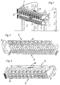
- the multiple connector block modules for solder-free insulation displacement connections the electrically insulated wires of trunk lines and subscriber lines a telephone exchange or the like includes in known Way a housing 1 made of plastic, in which there are a plurality of long sides Modularly spaced wiring means 4 for switching through each other assigned line wires are located, as well as with means for fastening the Terminal block on a mounting channel 10.
- the housing 1 is made in one piece with a plurality of modularly spaced chambers for receiving the Wiring means 4 from a narrow side and that the means for Attachment of the connection strip 1 to an assembly channel on the side of the strip arranged latch means 7 are for the transversal assembly of the bar for free access for the connection of the wires of the outside line or the Veins of the subscriber line.
- the pawl means 7 are essentially symmetrically designed for the installation of the terminal block in terms of handling by 180 °, as illustrated in FIG. 1.
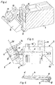
- 5 and 6 are the wiring means for switching the mutually assigned line wires a plurality of side by side in the Terminal block arranged, from the wiring side 2 for the trunk lines to the wiring page 3 for the subscriber lines, in essential flat wiring terminals 4, each with an insulation displacement slot 5, 5 'at both ends.
- the insulation displacement slot 5 of the wiring terminal 4 a cutting edge 8 assigned to cut off an excess length 15 ' Trunk line 15 when it is activated.
- the configuration is preferred such that the cutting edge 8 of the insulation displacement slot 5 with a predetermined Distance distant and tapering slit-shaped downwards and is designed to be closed and on one, at the wiring terminal 4 with the insulation displacement slot 5 parallel and rearward spaced U-shaped Cutting arm 9 is located (Fig. 6).
- FIGS. 4 and 5 there are 3 on the wiring side for the subscriber lines on the connection strip, a plurality of wiring swivel covers 6 articulated, each for receiving at least one wire 25 of the subscriber line and for their releasable connection in the relevant insulation displacement slot 5 '.
- the wiring swivel cover 6 by means of a film hinge 11 on the wiring side 3 for the subscriber lines on the connection strip attached.
- a significant improvement is achieved in that a transverse opening 13 to the wire receiving channel 14 on the wiring swivel cover 6 for passage one wiring terminal 4 each when switching on and as a pass-through for a test probe or the like by means of a penetrable, the leakage from a weather protection gelatin or a weather protection grease preventing membrane 12 is closed.
- the illustrations further show that the wiring pivot cover 6 for Inclusion and connection of twin wires are trained.
- the wiring swivel covers 6 are each in Locking position on the housing 1 can be locked via a snap lock 16, 16 ', wherein the snap closure 16, 16 'has different flank angles for Generation of different resistances when closing and opening the wiring swivel cover 6.
- the wiring swivel covers 6 each act together with a centering cam 17 on the housing 1 during the wiring process.
- the module multiple connection strip described above is therefore fully sufficient today's requirements, particularly with regard to rational production, free routing of the wires of the subscriber lines as well as in relation to a quick and easy connection of the electrically insulated wires of the Trunks and subscriber lines.
- the multiple connection strip fully protected against moisture. The latter will further improved by one on the wiring side (2) for the wires of the Snap-on outside line, with a weather protection gelatin or a weather protection grease filled lid 20 (Fig. 3).
Landscapes
- Engineering & Computer Science (AREA)
- Manufacturing & Machinery (AREA)
- Connections Arranged To Contact A Plurality Of Conductors (AREA)
- Multi-Conductor Connections (AREA)
- Structure Of Telephone Exchanges (AREA)
- Cable Accessories (AREA)
- Coupling Device And Connection With Printed Circuit (AREA)
Applications Claiming Priority (2)
| Application Number | Priority Date | Filing Date | Title |
|---|---|---|---|
| CH205698 | 1998-10-13 | ||
| CH205698 | 1998-10-13 |
Publications (2)
| Publication Number | Publication Date |
|---|---|
| EP0994528A2 true EP0994528A2 (fr) | 2000-04-19 |
| EP0994528A3 EP0994528A3 (fr) | 2000-07-19 |
Family
ID=4224893
Family Applications (1)
| Application Number | Title | Priority Date | Filing Date |
|---|---|---|---|
| EP99118821A Withdrawn EP0994528A3 (fr) | 1998-10-13 | 1999-09-23 | Réglette de bornes modulaires pour la connexion autodénudante, sans soudure de conducteurs électriques isolés |
Country Status (7)
| Country | Link |
|---|---|
| EP (1) | EP0994528A3 (fr) |
| JP (1) | JP2000175226A (fr) |
| KR (1) | KR20000034990A (fr) |
| CN (1) | CN1250963A (fr) |
| AU (1) | AU5020099A (fr) |
| PL (1) | PL335961A1 (fr) |
| TW (1) | TW429725B (fr) |
Cited By (2)
| Publication number | Priority date | Publication date | Assignee | Title |
|---|---|---|---|---|
| WO2007028550A1 (fr) * | 2005-09-06 | 2007-03-15 | Ccs Technology, Inc. | Fiche d'interconnexion |
| EP1953874A2 (fr) | 2007-02-02 | 2008-08-06 | INARCA S.p.A. | Connecteur électrique |
Families Citing this family (6)
| Publication number | Priority date | Publication date | Assignee | Title |
|---|---|---|---|---|
| KR100508972B1 (ko) * | 2001-03-31 | 2005-08-17 | 주식회사 케이티 | 통신 케이블용 단자체 분리형 단자판 |
| KR100440051B1 (ko) * | 2001-05-02 | 2004-07-14 | 대은전자 주식회사 | 스플리터 단자반 |
| TWI297559B (en) * | 2006-03-06 | 2008-06-01 | 3M Innovative Properties Co | Cross connect terminal block |
| US7530836B2 (en) | 2007-04-30 | 2009-05-12 | 3M Innovative Properties Company | Cap for telecommunications cross connect block |
| DE102016112758B4 (de) * | 2016-07-12 | 2020-06-18 | Lisa Dräxlmaier GmbH | Halteteil und verfahren zum befestigen von elektrischen leitungen sowie leitungsanordnung in einem fahrzeug |
| CN108899660B (zh) * | 2018-07-05 | 2020-05-15 | 菲尼克斯亚太电气(南京)有限公司 | 一种idc免剥线接线机构 |
Family Cites Families (7)
| Publication number | Priority date | Publication date | Assignee | Title |
|---|---|---|---|---|
| US4684195A (en) * | 1985-12-19 | 1987-08-04 | American Telephone And Telegraph Company, At&T Bell Laboratories | Solderless electrical connector |
| US4981443A (en) * | 1989-12-21 | 1991-01-01 | General Motors Corporation | Diagnostic connector tap |
| WO1992008255A1 (fr) * | 1990-10-26 | 1992-05-14 | The Siemon Company | Borne et bloc de connexion |
| US5281163A (en) * | 1991-09-23 | 1994-01-25 | Minnesota Mining And Manufacturing Company | Cross connect system for telecommunications systems |
| US5356309A (en) * | 1994-01-26 | 1994-10-18 | Porta Systems Corp. | Connector block with releasable mounting |
| US5802170A (en) * | 1994-05-19 | 1998-09-01 | Tii Industries, Inc. | Customer bridge module |
| FR2732164B1 (fr) * | 1995-03-20 | 1997-04-30 | Alcatel Cable Interface | Reglette de connexion de lignes a haut debit et ensemble resultant de connexion |
-
1999
- 1999-09-23 TW TW088116343A patent/TW429725B/zh not_active IP Right Cessation
- 1999-09-23 EP EP99118821A patent/EP0994528A3/fr not_active Withdrawn
- 1999-09-29 AU AU50200/99A patent/AU5020099A/en not_active Abandoned
- 1999-10-12 JP JP11289486A patent/JP2000175226A/ja not_active Withdrawn
- 1999-10-12 PL PL99335961A patent/PL335961A1/xx unknown
- 1999-10-13 KR KR1019990044197A patent/KR20000034990A/ko not_active Withdrawn
- 1999-10-13 CN CN99121354A patent/CN1250963A/zh active Pending
Cited By (3)
| Publication number | Priority date | Publication date | Assignee | Title |
|---|---|---|---|---|
| WO2007028550A1 (fr) * | 2005-09-06 | 2007-03-15 | Ccs Technology, Inc. | Fiche d'interconnexion |
| EP1953874A2 (fr) | 2007-02-02 | 2008-08-06 | INARCA S.p.A. | Connecteur électrique |
| EP1953874A3 (fr) * | 2007-02-02 | 2009-09-09 | INARCA S.p.A. | Connecteur électrique |
Also Published As
| Publication number | Publication date |
|---|---|
| TW429725B (en) | 2001-04-11 |
| KR20000034990A (ko) | 2000-06-26 |
| CN1250963A (zh) | 2000-04-19 |
| JP2000175226A (ja) | 2000-06-23 |
| AU5020099A (en) | 2000-04-20 |
| PL335961A1 (en) | 2000-04-25 |
| EP0994528A3 (fr) | 2000-07-19 |
Similar Documents
| Publication | Publication Date | Title |
|---|---|---|
| DE2850093C2 (de) | Halterungsanordnung für Schaltungsplatten | |
| DE19652422C1 (de) | Anschlußleiste | |
| DE69803532T2 (de) | Verbindungsmodul für zwei einpaarige Leitungen | |
| DE69307224T2 (de) | Steckdose von Typ "Modular Jack" mit integrierten Anschlüssen | |
| DE2406426A1 (de) | Werkzeug zum elektrischen verbinden von anschlussdraehten mit kontaktelementen | |
| DE69503112T2 (de) | Ein Bauelement für eine Schaltung und eine Anschlussdose | |
| EP1764871A1 (fr) | Système de connexion pour réalisation des branchements des conducteurs continus | |
| EP3734771B1 (fr) | Ensemble comprenant un connecteur électrique et un élément fonctionnel | |
| DE69403400T2 (de) | Schnellverbindungsmodul von zwei monopolaren Fernsprecherlinien | |
| DE102016103439B4 (de) | Kontaktstelle eines Flachleiters | |
| DE2428783A1 (de) | Verschwenkbarer anschlussblock | |
| EP0889550B1 (fr) | Recouvrement pour bornes avec une couverture de protection | |
| EP0994528A2 (fr) | Réglette de bornes modulaires pour la connexion autodénudante, sans soudure de conducteurs électriques isolés | |
| DE102013019725B4 (de) | Steckerbrücke sowie Verfahren zum Herstellen eines Steckers | |
| EP1286421B1 (fr) | Borne électrique | |
| DE2750540C2 (fr) | ||
| EP3716408A1 (fr) | Protection flexible contre les contacts pour un raccordement électrique | |
| AT504455A1 (de) | Schaltgerät | |
| EP0543173B1 (fr) | Dispositif de connexion et de branchement de câbles d'installation, en particulier distributeur, boîte de jonction ou boîte de distribution pour câbles de télécommunication | |
| DE2847116A1 (de) | Kabelverbindung fuer waehlvermittlungsanlagen | |
| DE3836668C1 (fr) | ||
| EP1353350B1 (fr) | Interrupteur auxiliaire | |
| EP1014499B1 (fr) | Dispositif de soulagement de la traction pour des systèmes modulaires avec des sections de connexions modulaires | |
| DE7818113U1 (de) | Elektrischer Verbinder | |
| DE69622016T2 (de) | Stecker mit integrierten Anschlüssen und Rückwandverbindung mit Schneidkontakten |
Legal Events
| Date | Code | Title | Description |
|---|---|---|---|
| PUAI | Public reference made under article 153(3) epc to a published international application that has entered the european phase |
Free format text: ORIGINAL CODE: 0009012 |
|
| AK | Designated contracting states |
Kind code of ref document: A2 Designated state(s): AT DE FR GB IT |
|
| AX | Request for extension of the european patent |
Free format text: AL;LT;LV;MK;RO;SI |
|
| PUAL | Search report despatched |
Free format text: ORIGINAL CODE: 0009013 |
|
| AK | Designated contracting states |
Kind code of ref document: A3 Designated state(s): AT BE CH CY DE DK ES FI FR GB GR IE IT LI LU MC NL PT SE |
|
| AX | Request for extension of the european patent |
Free format text: AL;LT;LV;MK;RO;SI |
|
| 17P | Request for examination filed |
Effective date: 20010119 |
|
| AKX | Designation fees paid |
Free format text: AT DE FR GB IT |
|
| STAA | Information on the status of an ep patent application or granted ep patent |
Free format text: STATUS: THE APPLICATION HAS BEEN WITHDRAWN |
|
| 18D | Application deemed to be withdrawn |
Effective date: 20030401 |
|
| 18W | Application withdrawn |
Effective date: 20030718 |