EP0994541B1 - Trägerstruktur für Gaslaserkammer und -Optik - Google Patents
Trägerstruktur für Gaslaserkammer und -Optik Download PDFInfo
- Publication number
- EP0994541B1 EP0994541B1 EP99120466A EP99120466A EP0994541B1 EP 0994541 B1 EP0994541 B1 EP 0994541B1 EP 99120466 A EP99120466 A EP 99120466A EP 99120466 A EP99120466 A EP 99120466A EP 0994541 B1 EP0994541 B1 EP 0994541B1
- Authority
- EP
- European Patent Office
- Prior art keywords
- chamber
- track
- support
- laser
- support frame
- Prior art date
- Legal status (The legal status is an assumption and is not a legal conclusion. Google has not performed a legal analysis and makes no representation as to the accuracy of the status listed.)
- Expired - Lifetime
Links
- 230000003287 optical effect Effects 0.000 claims description 25
- 230000008878 coupling Effects 0.000 claims description 4
- 238000010168 coupling process Methods 0.000 claims description 4
- 238000005859 coupling reaction Methods 0.000 claims description 4
- 229920002379 silicone rubber Polymers 0.000 description 7
- 229910000831 Steel Inorganic materials 0.000 description 2
- 230000000694 effects Effects 0.000 description 2
- 238000009434 installation Methods 0.000 description 2
- 239000002184 metal Substances 0.000 description 2
- 229910052751 metal Inorganic materials 0.000 description 2
- 239000010959 steel Substances 0.000 description 2
- YCKRFDGAMUMZLT-UHFFFAOYSA-N Fluorine atom Chemical compound [F] YCKRFDGAMUMZLT-UHFFFAOYSA-N 0.000 description 1
- 229910001030 Iron–nickel alloy Inorganic materials 0.000 description 1
- 230000008602 contraction Effects 0.000 description 1
- 239000010432 diamond Substances 0.000 description 1
- 229920001971 elastomer Polymers 0.000 description 1
- 229910052731 fluorine Inorganic materials 0.000 description 1
- 239000011737 fluorine Substances 0.000 description 1
- 238000002347 injection Methods 0.000 description 1
- 239000007924 injection Substances 0.000 description 1
- 238000001459 lithography Methods 0.000 description 1
- 239000000463 material Substances 0.000 description 1
- 150000002739 metals Chemical class 0.000 description 1
Images



Classifications
-
- G—PHYSICS
- G02—OPTICS
- G02B—OPTICAL ELEMENTS, SYSTEMS OR APPARATUS
- G02B7/00—Mountings, adjusting means, or light-tight connections, for optical elements
-
- H—ELECTRICITY
- H01—ELECTRIC ELEMENTS
- H01S—DEVICES USING THE PROCESS OF LIGHT AMPLIFICATION BY STIMULATED EMISSION OF RADIATION [LASER] TO AMPLIFY OR GENERATE LIGHT; DEVICES USING STIMULATED EMISSION OF ELECTROMAGNETIC RADIATION IN WAVE RANGES OTHER THAN OPTICAL
- H01S3/00—Lasers, i.e. devices using stimulated emission of electromagnetic radiation in the infrared, visible or ultraviolet wave range
- H01S3/02—Constructional details
-
- H—ELECTRICITY
- H01—ELECTRIC ELEMENTS
- H01S—DEVICES USING THE PROCESS OF LIGHT AMPLIFICATION BY STIMULATED EMISSION OF RADIATION [LASER] TO AMPLIFY OR GENERATE LIGHT; DEVICES USING STIMULATED EMISSION OF ELECTROMAGNETIC RADIATION IN WAVE RANGES OTHER THAN OPTICAL
- H01S3/00—Lasers, i.e. devices using stimulated emission of electromagnetic radiation in the infrared, visible or ultraviolet wave range
- H01S3/14—Lasers, i.e. devices using stimulated emission of electromagnetic radiation in the infrared, visible or ultraviolet wave range characterised by the material used as the active medium
- H01S3/22—Gases
- H01S3/223—Gases the active gas being polyatomic, i.e. containing two or more atoms
- H01S3/225—Gases the active gas being polyatomic, i.e. containing two or more atoms comprising an excimer or exciplex
Definitions
- This invention relates to gas lasers and in particular to support structures for such lasers.
- a gain medium is produced in a laser chamber by a discharge through a gas between two electrodes.
- a gas between two electrodes.
- this circulation is provided by a blower with a tangential blower blade structure located inside the laser chamber which is driven by an electric motor and supported by bearings.
- the present invention provides a chamber/optics support structure for a laser having a laser chamber with a vibration source.
- the chamber and the laser resonance cavity optical elements are supported on a platform.
- the chamber is supported by a plurality of wheels which in turn rests on two tracks on track supports mounted on the platform.
- a flexible clamp flexibly clamps the chamber in a horizontal position to align it with the resonance cavity optical elements and to substantially decouple vibration between the chamber vibration source to the optical elements in a frequency range of concern.
- the invention is especially useful for positioning the heavy laser chamber of a narrow band excimer laser and for decoupling vibrations resulting from its blower from the lasers line narrowing module and output coupler.
- the plurality of wheels is three wheels, two of which rest in a V-groove track and one of which rests on a flat track.
- This preferred embodiment uses two flexible clamps each having an adjustment bolt and four symmetrically spaced silicon rubber vibration isolators. Precise horizontal alignment of the chamber is accomplished using the adjustment bolt which is then held in position with a lock nut and a clamping bolt. Silicon rubber dampers in the isolators decouple horizontal chamber vibrations from the optical elements.
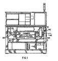
- FIG. 1 is a drawing showing the general location of the chamber and some of the optical equipment of a state of the art narrow band excimer laser used as a light source for integrated circuit lithography.
- the drawing shows laser chamber 156, line narrowing module 120, output coupler module 130 and wavemeter 140 and indicates the direction of output beam 142.
- This equipment plus numerous other equipment including electrical and gas support equipment needed for the operation of the laser are mounted on a laser support frame.
- a detailed description of a laser support frame for an excimer laser is described in patent application Serial No. 08/583,380 assigned to the assignee of the present application.
- FIG 5A of that application is substantially reproduced in this application as FIG. 1A.
- Laser support frame 100 includes chamber/optics platform 150 which is mounted within frame 100 on at three attachment points each of which points is a swivel joint comprising a ball-cup joint as described in patent application Serial No. 08/583,380.
- the purpose of this special mounting is to prevent any distortion of chamber/optics platform 150 as a result of forces applied to laser support frame 100.
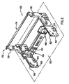
- FIG. 2 shows a chamber-optics support frame 152 which in this preferred embodiment is bolted onto chamber/optics platform 150 with eight bolts at locations 154.
- support frame 152 supports a laser chamber on platform 150 and also supports the associated resonance cavity optics also on platform 150, and permits alignment of the laser optics with the laser chamber.
- the frame is designed to avoid or minimize distortions in the optical equipment resulting from thermal and vibrational purturbations in the chamber. This is accomplished as follows:
- the bottom portion 156A of chamber 156 as shown in FIG. 3 is supported vertically by two cross ribs 160 and 164.
- the bottom of chamber 156 is equipped with three metal wheels (not shown) two of which roll in V-track 158 in cross rib 160 and one of which (also not shown) rolls on flat track 162 on cross rib 164 during installation of the chamber and during operation these wheels provide vertical support for the chamber.
- two additional wheels are provided on the flat track side of the chamber to aid in chamber installation and removal, but these wheels are elevated so that they do not furnish any support during laser operation.
- the chamber is supported and aligned horizontally by flexible clamps 166 and 168 which attach to chamber bottom 156A and frame element 170 as shown in FIG. 3.
- Optics support structure 172 consists primarily of output coupler support frame 176, line narrowing module support frame 178 and three cross bars 174 comprised of a iron-nickel alloy sold under the designation INVAR-36 by High Temp Metals, Inc. with offices in Sylmar, California. This material is designed to provide a minimal (almost zero) coefficient of thermal expansion in the temperature range of interest.
- the three bars are rigidly attached to output coupler support frame 176 and to line narrowing module support frame 178 but the bars are not directly attached to cross braces 160 or 164 but pass through holes in these cross braces.
- Optics support structure 172 is kinematically mounted on platform 150.
- Frames 176 and 178 are attached to cross braces 164 and 160 respectively with bearings so as to avoid any distortion of the optics support structure.
- Frame 176 is attached to cross brace 162 with a single radial bearing which permits rotation of frame 176 radially but restricts axial (i.e., in the direction of rods 174) motion, cross (i.e. in the direction of cross brace 164) motion and vertical motion of support structure 172.
- Frame 178 is attached to cross brace 160 in two places, first with an axial bearing which permits movement in the axial direction and second with a slot mounted axial bearing which permits axial motion and motion in the cross direction.
- flexible clamps 166 and 168 are used to align and to flexibly clamp chamber 156 horizontally in chamber optics support frame 152.
- the chamber bottom 156A is shown in FIG. 3 clamped into position with flexible clamps 160 and 168.
- An exploded assembly drawing of flexible clamp 166 is shown in FIG. 4A. It is comprised of interface plate 180, mounting plate 181, four silicon rubber Series AM 004 vibration isolators 182 available from Lord Corporation, Erie, Pennsylvania, four travel limiting washers 183, an isolator cover 184, an adjustment knob 185, an adjustment lock nut 186 and a clamping bolt 187.
- FIGS. 4B, 4C and 4D are cross sectional drawings of flexible clamps 168.
- Flexible clamp 166 is just like flexible clamp 168 except for the location of some of the bolt holes.
- FIG. 4B is a cross section through the center of silicon rubber vibration isolators 182.
- FIG. 4C is a cross section through the center of adjustment knob 185.
- FIG. 4D is a cross section through the center of two of the bolts holding down each of the vibration isolators.
- FIG. 4E is disjointed cross section drawing through the center of isolators 182 and also through the center of adjustment knob 185.
- FIG. 4E demonstrates the functioning of the flexible clamps.
- isolator 182 is comprised of steel top plate 182A, steel isolator central cylinder 182B and silicon rubber damper 182C.
- Damper 182C is glued to cylinder 182B and top plate 182A and each top plate 182A is bolted to mounting plate 181 with four bolts shown in FIG. 4A but the bolts are not shown in FIG. 4E.
- Cylinder 182B and travel limiting washer 183 are rigidly attached to interface plate 180 with hold down bolt 182D and a lock washer as shown in FIG. 4E.
- interface plate 180 is rigidly attached to chamber bottom 156A.
- Adjustment bolt 185 threads through mounting plate 181 and rests solidly against frame 170 as shown at 171.
- Lock nut 186 holds bolt 185 in position.
- Clamping bolt 187 passes through the center of adjustment bolt 185 and screws into threaded receptor 187A to rigidly attach mounting plate 181 and other components within boundary line 190 (shown on FIG. 4E) to frame element 170.
- the chamber is isolated in the cross horizontal direction by the eight silicon rubber dampers 182C in the two flexible clamps.
- Frame 100 is very stiff in the vertical direction so that the transfer of vertical vibrations from the this chamber through the frame elements to optical components is very small.
- the frame is much more susceptible to high frequency cross horizontal vibration but these are substantially isolated from the frame by the eight dampers 182C.
- FIG. 5A shows the transmissibility of silicon rubber dampers 182C as a function of frequency and FIG. 5B shows the deflection of the dampers as a function of load. Since the chamber is on rollers and tracks 158 and 162 are level the net steady state load on dampers 182C is zero.
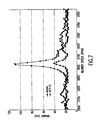
- FIG. 7 is a comparison of vibration data taken with a Balmac vibration monitor on an excimer laser having bearings which had been subjected to significant wear. The data represented by diamonds was acquired with the chamber mounted rigidly to frame element 170. The data represented by circles was acquired with the flexible clamps described above. With the rigid mounting, this particular laser displayed a substantial resonance with the blower operating at about 3070 rpm. The present invention greatly reduced the resonance coupling.
- FIG. 6B shows plots of wavelength variations as a function of blower speed for a laser with worn bearings with the flexible clamp and with rigid clamps.
- the bad data point at about 3350 results from a fluorine injection and is unrelated to vibrations.
- FIG. 6A is a similar chart with newer bearings. Comparisons are shown for rigid clamps (circle), a simple clamp made with a rubber pad sandwich (triangles) and the above described flexible clamp.
- Chamber 156 is rolled into approximate position on tracks 158 and 162.
- Interface plate 182 is bolted onto chamber bottom 156A. With cover 181 removed mounting plate 181 is bolted onto interface plate 182 using isolator bolts 182D. Cover 181 is installed and adjustment bolt is screwed into mounting plate until the tip of adjustment bolt 185 rests against frame element 170 as shown at 171. Adjustment bolt 185 is then adjusted to align chamber 156 with the laser optics in line narrowing module 120 and output coupler module 130.
- lock nut 186 When the laser is aligned lock nut 186 is tightened and lock bolt 187 is screwed into threaded nut 187A in frame element 170 to hold laser chamber in place relative to frame element 170.
- lock bolt 187 When the laser is aligned lock nut 186 is tightened and lock bolt 187 is screwed into threaded nut 187A in frame element 170 to hold laser chamber in place relative to frame element 170.
Landscapes
- Physics & Mathematics (AREA)
- Optics & Photonics (AREA)
- Electromagnetism (AREA)
- General Physics & Mathematics (AREA)
- Engineering & Computer Science (AREA)
- Plasma & Fusion (AREA)
- Lasers (AREA)
- Exposure And Positioning Against Photoresist Photosensitive Materials (AREA)
Claims (8)
- Tragkonstruktion für eine Gaslaserkammer und eine Optik zum Tragen von optischen Elementen eines optischen Resonators und einer Laserkammer (156), die ein Verstärkungsmedium begrenzt, wobei die Kammer eine Erschütterungsquelle definiert und mindestens drei Räder (1, 2, 3) aufweist, mit:A) einem Lasertragrahmen (100)B) einer Tragplattform (150) für die Kammer und die Optik, die auf dem Lasertragrahmen (100) angebracht ist,C) mindestens zwei optischen Elementen des optischen Resonators, die auf der Tragplattform (150) für die Kammer und die Optik angebracht sind,D) einem ersten Führungselement (160), das eine erste Führung (158) definiert, und einem zweiten Führungselement (162), das eine zweite Führung (162) definiert, wobei die Laserkammer (156) mit den mindestens drei Rädern auf der ersten und der zweiten Führung (158, 162) rollend gelagert ist, undE) mindestens einem elastischen Befestigungselement (166, 168) zum elastischen Befestigen der Kammer (156) in einer gewünschten horizontalen Position zum Ausrichten der Kammer (156) mit den optischen Elementen des optischen Resonators und zum Verringern einer Übertragung von Erschütterungen von der Erschütterungsquelle der Kammer (156) auf die optischen Elemente des optischen Resonators.
- Tragkonstruktion nach Anspruch 1, in der die mindestens drei Räder (1, 2, 3) drei Räder (1, 2, 3) sind.
- Tragkonstruktion nach Anspruch 2, in der die erste Führung eine Führungsrille (158) ist, wobei zwei der drei Räder (1, 2) in der Führungsrille (158) gelagert sind, und die zweite Führung eine flache Führung (162) ist, wobei ein Rad (1) auf der flachen Führung (162) gelagert ist.
- Tragkonstruktion nach Anspruch 1, in der das elastische Befestigungselement (166, 168) eine Befestigungsplatte (181) und einen Justierbolzen (187), der in einem Ausmaß, das zum Ausrichten des Verstärkungsmediums in der Kammer mit den optischen Elementen des optischen Resonators erforderlich ist, durch die Befestigungsplatte geschraubt ist, umfasst.
- Tragkonstruktion nach Anspruch 4, in der ein Teil von jedem des mindestens einen Befestigungselements (166, 168) einen ersten Teil (180), der fest an der Kammer (156) befestigt ist, und einen zweiten Teil (181), der fest an der Tragplattform (150) für die Kammer und die Optik befestigt ist, definiert, und wobei das elastische Befestigungselement (166, 168) mehrere Dämpfer (182) umfasst, die so angeordnet sind, dass sie den ersten Teil von dem zweiten Teil trennen.
- Tragkonstruktion nach Anspruch 4, in der das mindestens eine Befestigungselement aus zwei Befestigungselementen (166, 168) besteht, und in der die mehreren Dämpfer vier Dämpfer (182) sind.
- Tragkonstruktion für eine Gaslaserkammer und eine Optik zum Tragen von optischen Elementen eines optischen Resonators und einer Laserkammer (156), die ein Verstärkungsmedium begrenzt, wobei die Kammer eine Erschütterungsquelle definiert, und mindestens drei Räder (1, 2, 3) aufweist, mit:A) einem Lasertragrahmen (100)B) einer Tragplattform (150) für die Kammer und die Optik, die auf dem Lasertragrahmen (100) angebracht ist,C) mindestens zwei optischen Elementen des optischen Resonators, die auf der Tragplattform (150) für die Kammer und die Optik angebracht sind,D) einer Tragkonstruktion (172) für die Optik, die einen ersten Tragrahmen (176) für optische Elemente des optischen Resonators und einen zweiten Tragrahmen (178) für optische Elemente des optischen Resonators umfasst, wobei der erste Tragrahmen (176) für optische Elemente mittels eines ersten Lagers an einem zweiten Führungselement (164) angebracht ist, und der zweite Tragrahmen (178) für optische Elemente mittels eines zweiten Lagers an einem ersten Führungselement (160) angebracht ist und der erste Tragrahmen (178) für optische Elemente mit Hilfe mehrerer Stäbe (174) starr an dem zweiten Tragrahmen (176) für optische Elemente befestigt ist.
- Tragkonstruktion nach Anspruch 7, in der das erste Lager eine Bewegung des ersten Tragrahmens (176) für optische Elemente relativ zum zweiten Führungselement (164) in der axialen Richtung erlaubt und das zweite Lager keine Bewegung des zweiten Tragrahmens (178) für optische Elemente relativ zum ersten Führungselement in der axialen Richtung erlaubt.
Applications Claiming Priority (2)
| Application Number | Priority Date | Filing Date | Title |
|---|---|---|---|
| US174155 | 1998-10-16 | ||
| US09/174,155 US6109574A (en) | 1996-01-05 | 1998-10-16 | Gas laser chamber/optics support structure |
Publications (3)
| Publication Number | Publication Date |
|---|---|
| EP0994541A2 EP0994541A2 (de) | 2000-04-19 |
| EP0994541A3 EP0994541A3 (de) | 2002-09-25 |
| EP0994541B1 true EP0994541B1 (de) | 2008-01-02 |
Family
ID=22635066
Family Applications (1)
| Application Number | Title | Priority Date | Filing Date |
|---|---|---|---|
| EP99120466A Expired - Lifetime EP0994541B1 (de) | 1998-10-16 | 1999-10-14 | Trägerstruktur für Gaslaserkammer und -Optik |
Country Status (4)
| Country | Link |
|---|---|
| US (1) | US6109574A (de) |
| EP (1) | EP0994541B1 (de) |
| JP (1) | JP2000183426A (de) |
| DE (1) | DE69937867T2 (de) |
Families Citing this family (27)
| Publication number | Priority date | Publication date | Assignee | Title |
|---|---|---|---|---|
| US6586757B2 (en) | 1997-05-12 | 2003-07-01 | Cymer, Inc. | Plasma focus light source with active and buffer gas control |
| US6757316B2 (en) | 1999-12-27 | 2004-06-29 | Cymer, Inc. | Four KHz gas discharge laser |
| US6801560B2 (en) * | 1999-05-10 | 2004-10-05 | Cymer, Inc. | Line selected F2 two chamber laser system |
| US6590922B2 (en) | 1999-09-27 | 2003-07-08 | Cymer, Inc. | Injection seeded F2 laser with line selection and discrimination |
| US6795474B2 (en) * | 2000-11-17 | 2004-09-21 | Cymer, Inc. | Gas discharge laser with improved beam path |
| US7856044B2 (en) | 1999-05-10 | 2010-12-21 | Cymer, Inc. | Extendable electrode for gas discharge laser |
| US6556600B2 (en) | 1999-09-27 | 2003-04-29 | Cymer, Inc. | Injection seeded F2 laser with centerline wavelength control |
| US6466601B1 (en) | 2001-04-13 | 2002-10-15 | Cymer, Inc. | Beam seal for line narrowed production laser |
| US7180081B2 (en) * | 2000-06-09 | 2007-02-20 | Cymer, Inc. | Discharge produced plasma EUV light source |
| US6425559B1 (en) | 2000-09-29 | 2002-07-30 | Cymer, Inc. | Gas laser chamber with vertical vibration isolator |
| US6839372B2 (en) * | 2000-11-17 | 2005-01-04 | Cymer, Inc. | Gas discharge ultraviolet laser with enclosed beam path with added oxidizer |
| US6928093B2 (en) * | 2002-05-07 | 2005-08-09 | Cymer, Inc. | Long delay and high TIS pulse stretcher |
| US7088758B2 (en) | 2001-07-27 | 2006-08-08 | Cymer, Inc. | Relax gas discharge laser lithography light source |
| US7671349B2 (en) * | 2003-04-08 | 2010-03-02 | Cymer, Inc. | Laser produced plasma EUV light source |
| US20040101018A1 (en) * | 2002-08-28 | 2004-05-27 | Syb Leijenaar | Suspension system for laser discharge unit |
| US20050271110A1 (en) * | 2003-08-22 | 2005-12-08 | Rainer Paetzel | Excimer laser system with stable beam output |
| US7064908B2 (en) * | 2004-04-21 | 2006-06-20 | The Boeing Company | Laser beam jitter reduction device on a laser optical bench |
| US20050286599A1 (en) * | 2004-06-29 | 2005-12-29 | Rafac Robert J | Method and apparatus for gas discharge laser output light coherency reduction |
| US8379687B2 (en) | 2005-06-30 | 2013-02-19 | Cymer, Inc. | Gas discharge laser line narrowing module |
| US7321607B2 (en) * | 2005-11-01 | 2008-01-22 | Cymer, Inc. | External optics and chamber support system |
| US7655925B2 (en) * | 2007-08-31 | 2010-02-02 | Cymer, Inc. | Gas management system for a laser-produced-plasma EUV light source |
| US7812329B2 (en) * | 2007-12-14 | 2010-10-12 | Cymer, Inc. | System managing gas flow between chambers of an extreme ultraviolet (EUV) photolithography apparatus |
| US8519366B2 (en) * | 2008-08-06 | 2013-08-27 | Cymer, Inc. | Debris protection system having a magnetic field for an EUV light source |
| JP5687488B2 (ja) | 2010-02-22 | 2015-03-18 | ギガフォトン株式会社 | 極端紫外光生成装置 |
| CN103259159B (zh) * | 2013-04-26 | 2016-05-04 | 中国科学院光电研究院 | 光机分离式双腔准分子激光器整机框架系统 |
| CN104595642B (zh) * | 2015-01-06 | 2016-05-04 | 山东大学 | 一种二自由度压电驱动纳米定位平台 |
| CN118938423B (zh) * | 2024-10-15 | 2025-03-04 | 中国科学院精密测量科学与技术创新研究院 | 一种低振动灵敏度的可搬运空间光学参考腔 |
Family Cites Families (8)
| Publication number | Priority date | Publication date | Assignee | Title |
|---|---|---|---|---|
| US4760583A (en) * | 1983-05-06 | 1988-07-26 | Coherent, Inc. | Laser delivery system |
| US4534047A (en) * | 1984-01-06 | 1985-08-06 | The Perkin-Elmer Corporation | Mask ring assembly for X-ray lithography |
| US4719641A (en) * | 1985-11-08 | 1988-01-12 | Summit Technology, Inc. | Multiple chamber laser containment system |
| US4818089A (en) * | 1987-04-24 | 1989-04-04 | Coherent, Inc. | Kinematic resonator support |
| DE3917408A1 (de) * | 1988-06-06 | 1989-12-07 | Takenaka Corp | Daempfungssockel |
| US5040953A (en) * | 1988-09-19 | 1991-08-20 | Copeland Corporation | Mounting system |
| DE4313675C1 (de) * | 1993-04-22 | 1994-05-26 | Mannesmann Ag | Lichtsetzgerät |
| US5863017A (en) * | 1996-01-05 | 1999-01-26 | Cymer, Inc. | Stabilized laser platform and module interface |
-
1998
- 1998-10-16 US US09/174,155 patent/US6109574A/en not_active Expired - Lifetime
-
1999
- 1999-10-14 EP EP99120466A patent/EP0994541B1/de not_active Expired - Lifetime
- 1999-10-14 DE DE69937867T patent/DE69937867T2/de not_active Expired - Lifetime
- 1999-10-18 JP JP11331723A patent/JP2000183426A/ja active Pending
Also Published As
| Publication number | Publication date |
|---|---|
| EP0994541A3 (de) | 2002-09-25 |
| DE69937867T2 (de) | 2009-01-02 |
| EP0994541A2 (de) | 2000-04-19 |
| US6109574A (en) | 2000-08-29 |
| DE69937867D1 (de) | 2008-02-14 |
| JP2000183426A (ja) | 2000-06-30 |
Similar Documents
| Publication | Publication Date | Title |
|---|---|---|
| US6109574A (en) | Gas laser chamber/optics support structure | |
| US12269396B2 (en) | Camera mounting device for a vehicle | |
| US4957359A (en) | Spring biased mirror assembly with electromagnetic release means | |
| DE60220166T2 (de) | Linienverschmälerungseinheit mit flexuralgitteranbringung | |
| US5070708A (en) | Floating frame mounting system and method for a refrigerator | |
| KR102577850B1 (ko) | 광학부용 일체형 유연 힌지 마운트 | |
| KR101134210B1 (ko) | 반도체 리토그래피용 광학 서브어셈블리 및 투영 대물렌즈 | |
| US6425559B1 (en) | Gas laser chamber with vertical vibration isolator | |
| US20060045151A1 (en) | External cavity wavelength stabilized Raman lasers insensitive to temperature and/or external mechanical stresses, and Raman analyzer utilizing the same | |
| AU603497B2 (en) | High-speed axial flow type gas laser oscillator | |
| US4646336A (en) | Laser generator | |
| US4646310A (en) | Flow control device for a laser generator | |
| EP0357748B1 (de) | Gerat und verfahren zur spannungsfreien lagerung optischer bauteile | |
| US4245195A (en) | Laser optical resonator assembly | |
| Susini et al. | Adaptive x‐ray mirror prototype: First results | |
| US5151916A (en) | Electric discharge tube for gas laser | |
| US6466601B1 (en) | Beam seal for line narrowed production laser | |
| RU2029421C1 (ru) | Оптический резонатор мощного лазера | |
| US20050271110A1 (en) | Excimer laser system with stable beam output | |
| JPS6350083A (ja) | ガスレ−ザ装置 | |
| US20030222530A1 (en) | Horizontal-axis electrical machine | |
| US20040101018A1 (en) | Suspension system for laser discharge unit | |
| JP2610633B2 (ja) | 干渉計構造体の取り付け装置および方法 | |
| RU2102824C1 (ru) | Твердотельный лазер | |
| US4893780A (en) | Gas blower support device for laser generators |
Legal Events
| Date | Code | Title | Description |
|---|---|---|---|
| PUAI | Public reference made under article 153(3) epc to a published international application that has entered the european phase |
Free format text: ORIGINAL CODE: 0009012 |
|
| AK | Designated contracting states |
Kind code of ref document: A2 Designated state(s): AT BE CH CY DE DK ES FI FR GB GR IE IT LI LU MC NL PT SE |
|
| AX | Request for extension of the european patent |
Free format text: AL;LT;LV;MK;RO;SI |
|
| PUAL | Search report despatched |
Free format text: ORIGINAL CODE: 0009013 |
|
| AK | Designated contracting states |
Kind code of ref document: A3 Designated state(s): AT BE CH CY DE DK ES FI FR GB GR IE IT LI LU MC NL PT SE |
|
| AX | Request for extension of the european patent |
Free format text: AL;LT;LV;MK;RO;SI |
|
| 17P | Request for examination filed |
Effective date: 20030312 |
|
| AKX | Designation fees paid |
Designated state(s): DE FR GB NL |
|
| RAP1 | Party data changed (applicant data changed or rights of an application transferred) |
Owner name: CYMER, INC. |
|
| GRAP | Despatch of communication of intention to grant a patent |
Free format text: ORIGINAL CODE: EPIDOSNIGR1 |
|
| GRAS | Grant fee paid |
Free format text: ORIGINAL CODE: EPIDOSNIGR3 |
|
| GRAA | (expected) grant |
Free format text: ORIGINAL CODE: 0009210 |
|
| AK | Designated contracting states |
Kind code of ref document: B1 Designated state(s): DE FR GB NL |
|
| REG | Reference to a national code |
Ref country code: GB Ref legal event code: FG4D |
|
| REF | Corresponds to: |
Ref document number: 69937867 Country of ref document: DE Date of ref document: 20080214 Kind code of ref document: P |
|
| EN | Fr: translation not filed | ||
| PLBE | No opposition filed within time limit |
Free format text: ORIGINAL CODE: 0009261 |
|
| STAA | Information on the status of an ep patent application or granted ep patent |
Free format text: STATUS: NO OPPOSITION FILED WITHIN TIME LIMIT |
|
| 26N | No opposition filed |
Effective date: 20081003 |
|
| PG25 | Lapsed in a contracting state [announced via postgrant information from national office to epo] |
Ref country code: FR Free format text: LAPSE BECAUSE OF FAILURE TO SUBMIT A TRANSLATION OF THE DESCRIPTION OR TO PAY THE FEE WITHIN THE PRESCRIBED TIME-LIMIT Effective date: 20081024 |
|
| GBPC | Gb: european patent ceased through non-payment of renewal fee |
Effective date: 20081014 |
|
| PG25 | Lapsed in a contracting state [announced via postgrant information from national office to epo] |
Ref country code: GB Free format text: LAPSE BECAUSE OF NON-PAYMENT OF DUE FEES Effective date: 20081014 |
|
| REG | Reference to a national code |
Ref country code: DE Ref legal event code: R082 Ref document number: 69937867 Country of ref document: DE Representative=s name: GRUENECKER PATENT- UND RECHTSANWAELTE PARTG MB, DE Ref country code: DE Ref legal event code: R081 Ref document number: 69937867 Country of ref document: DE Owner name: CYMER, LLC (N.D.GES. D.STAATES NEVADA), SAN DI, US Free format text: FORMER OWNER: CYMER, INC., SAN DIEGO, CALIF., US |
|
| REG | Reference to a national code |
Ref country code: NL Ref legal event code: PD Owner name: KONA TECHNOLOGIES LLC; US Free format text: DETAILS ASSIGNMENT: VERANDERING VAN EIGENAAR(S), SAMENVOEGEN; FORMER OWNER NAME: CYMER, INC. Effective date: 20160930 Ref country code: NL Ref legal event code: HC Owner name: CYMER LLC; US Free format text: DETAILS ASSIGNMENT: VERANDERING VAN EIGENAAR(S), VERANDERING VAN NAAM VAN DE EIGENAAR(S); FORMER OWNER NAME: KONA TECHNOLOGIES LLC Effective date: 20160930 |
|
| PGFP | Annual fee paid to national office [announced via postgrant information from national office to epo] |
Ref country code: DE Payment date: 20171019 Year of fee payment: 19 |
|
| PGFP | Annual fee paid to national office [announced via postgrant information from national office to epo] |
Ref country code: NL Payment date: 20171019 Year of fee payment: 19 |
|
| REG | Reference to a national code |
Ref country code: DE Ref legal event code: R119 Ref document number: 69937867 Country of ref document: DE |
|
| REG | Reference to a national code |
Ref country code: NL Ref legal event code: MM Effective date: 20181101 |
|
| PG25 | Lapsed in a contracting state [announced via postgrant information from national office to epo] |
Ref country code: NL Free format text: LAPSE BECAUSE OF NON-PAYMENT OF DUE FEES Effective date: 20181101 Ref country code: DE Free format text: LAPSE BECAUSE OF NON-PAYMENT OF DUE FEES Effective date: 20190501 |