EP0994560A1 - Méthode et dispositif d'ajustement synchrone des organes mobiles, particulièrement des pieds de table - Google Patents
Méthode et dispositif d'ajustement synchrone des organes mobiles, particulièrement des pieds de table Download PDFInfo
- Publication number
- EP0994560A1 EP0994560A1 EP98811034A EP98811034A EP0994560A1 EP 0994560 A1 EP0994560 A1 EP 0994560A1 EP 98811034 A EP98811034 A EP 98811034A EP 98811034 A EP98811034 A EP 98811034A EP 0994560 A1 EP0994560 A1 EP 0994560A1
- Authority
- EP
- European Patent Office
- Prior art keywords
- electronics
- motor
- adjustment
- engine
- motors
- Prior art date
- Legal status (The legal status is an assumption and is not a legal conclusion. Google has not performed a legal analysis and makes no representation as to the accuracy of the status listed.)
- Withdrawn
Links
- 230000001360 synchronised effect Effects 0.000 title claims abstract description 11
- 238000000034 method Methods 0.000 title claims description 12
- 230000001105 regulatory effect Effects 0.000 claims abstract description 4
- 230000033228 biological regulation Effects 0.000 claims description 10
- 230000001133 acceleration Effects 0.000 claims description 8
- 230000015654 memory Effects 0.000 claims description 6
- 230000001276 controlling effect Effects 0.000 claims description 4
- 238000012544 monitoring process Methods 0.000 claims description 3
- 239000013598 vector Substances 0.000 claims description 3
- 230000001419 dependent effect Effects 0.000 claims 1
- 238000012937 correction Methods 0.000 abstract description 5
- 238000011017 operating method Methods 0.000 abstract 1
- 230000005540 biological transmission Effects 0.000 description 8
- 230000008859 change Effects 0.000 description 4
- 230000003111 delayed effect Effects 0.000 description 2
- 238000009434 installation Methods 0.000 description 2
- 230000001681 protective effect Effects 0.000 description 2
- 230000004044 response Effects 0.000 description 2
- 230000001960 triggered effect Effects 0.000 description 2
- 238000013459 approach Methods 0.000 description 1
- 230000001427 coherent effect Effects 0.000 description 1
- 239000004020 conductor Substances 0.000 description 1
- 230000008878 coupling Effects 0.000 description 1
- 238000010168 coupling process Methods 0.000 description 1
- 238000005859 coupling reaction Methods 0.000 description 1
- 238000013461 design Methods 0.000 description 1
- 238000001514 detection method Methods 0.000 description 1
- 230000006870 function Effects 0.000 description 1
- 238000004519 manufacturing process Methods 0.000 description 1
- 230000007246 mechanism Effects 0.000 description 1
- 238000013021 overheating Methods 0.000 description 1
- 230000008447 perception Effects 0.000 description 1
- 230000009467 reduction Effects 0.000 description 1
- 230000002123 temporal effect Effects 0.000 description 1
- 238000012546 transfer Methods 0.000 description 1
- 230000001052 transient effect Effects 0.000 description 1
- 238000009423 ventilation Methods 0.000 description 1
Images

Classifications
-
- H—ELECTRICITY
- H02—GENERATION; CONVERSION OR DISTRIBUTION OF ELECTRIC POWER
- H02P—CONTROL OR REGULATION OF ELECTRIC MOTORS, ELECTRIC GENERATORS OR DYNAMO-ELECTRIC CONVERTERS; CONTROLLING TRANSFORMERS, REACTORS OR CHOKE COILS
- H02P5/00—Arrangements specially adapted for regulating or controlling the speed or torque of two or more electric motors
- H02P5/46—Arrangements specially adapted for regulating or controlling the speed or torque of two or more electric motors for speed regulation of two or more dynamo-electric motors in relation to one another
- H02P5/50—Arrangements specially adapted for regulating or controlling the speed or torque of two or more electric motors for speed regulation of two or more dynamo-electric motors in relation to one another by comparing electrical values representing the speeds
-
- A—HUMAN NECESSITIES
- A47—FURNITURE; DOMESTIC ARTICLES OR APPLIANCES; COFFEE MILLS; SPICE MILLS; SUCTION CLEANERS IN GENERAL
- A47B—TABLES; DESKS; OFFICE FURNITURE; CABINETS; DRAWERS; GENERAL DETAILS OF FURNITURE
- A47B9/00—Tables with tops of variable height
Definitions
- the invention relates to a method for controlling a Multiple DC motors for synchronous adjustment of adjustment elements, e.g. telescopic table legs, at which to control the synchronism of the motors on the Motor applied electrical operating voltage is regulated.
- adjustment elements e.g. telescopic table legs
- the invention further relates to equipment for synchronous adjustment of telescopic adjustment elements, especially for length adjustment of table legs, with each Adjustment element of a DC motor on a telescopic part for turning a spindle in an adjusting nut on the other Telescopic part, with a regulation of the operating voltage of the Motor to influence the speed of rotation of the motor and with a regulation of the synchronous operation of the DC motors.
- the engine is controlled by buttons that control the voltage switch, controlled.
- the end position is recognized via Limit switches, which limit the current flow when the Interrupt end position.
- the adjustment speed is depending on load.
- the motor is controlled by a central operating and control electronics.
- the table position is recognized.
- the control electronics evaluate the Sensor signals off. Therefore, different positions are targeted approachable.
- each support or table leg There is a motor for each support or table leg arranged.
- the two or four motors are with sensors equipped for position detection and Serve speed monitoring.
- Each table has one central control unit. This detects the sensor signals and individually supplies each motor with metered energy.
- the slowest motor serves as the lead motor for the others. The faster engines are delayed until the slowest has reached the same position again.
- the aim of the invention is an inexpensive one To create adjustment device, which with minimal effort is expandable. It is supposed to put together a plurality of tables be adjustable. An extension of a table with one Additional tabletop should be without basic intervention in the Adjustment device may be possible.
- the object is achieved in that at least in a method of the type mentioned at the beginning an adjustment parameter, in particular the speed of rotation of the engine, each with an individual, the individual engine assigned engine electronics with an absolute setpoint is compared and if there is a deviation from this setpoint Motor electronics adjusts the operating voltage of the motor that the setpoint is reached if possible.
- the Motor electronics in the event of a non-correctable deviation of the assigned motor from a setpoint, in particular the Speed of rotation, a signal down and this signal from the central control electronics.
- the perception of the signal triggers a correction of the adjustment specification for everyone Motors off, so that the new adjustment specification from the previous specification of the motor not being reached is reached.
- the adjustment by control electronics can also different groups of motors different values be specified.
- control electronics advantageously control each individual Engine individually. This allows any engine to run individual setpoint or different groups of motors different setpoints are specified. Are further advantageous also groups of motors separately with one other address controllable. As a result, e.g. a Tilting of a table top by the control electronics be initiated.
- Setpoints, commands and signals are also advantageous Provide addresses and e.g. all motors via a data bus forwarded.
- the motor electronics expediently recognizes the information intended for them from the data supplied.
- a data bus there is also a radio or Infrared connection or the like conceivable.
- the Information can also be obtained through a supply line to get redirected.
- Such an open data bus network can therefore Have branches. This enables a very free one Arrangement of tables and at the same time a strong one simplified wiring.
- a practical execution uses one Pair of conductors as data bus and as supply line. To can modulate data to a power supply frequency become. However, it is preferred that the data transfer and a synchronization format transmitted between the data is provided with so much energy that this energy for Operating the motors is sufficient.
- each motor has separate motor electronics assigned to regulate the operating voltage and sensors.
- the engine electronics are designed such that a Deviation of the sensor signals from a setpoint Regulation of the operating voltage caused.
- This equipment allows an arrangement of the engine controlling electronics in the engine. This will make comparison for equipment with centrally arranged electronics large number, flexibility and expandability obstructing cables avoided.
- An inventive Equipment is made up of a variable number of Adjustment elements, each with motor electronics, whereby the number does not influence the design of the Has engine electronics. Therefore, the engine electronics are in one large number and therefore inexpensive to manufacture.
- a central control electronics is advantageous Control of the engine electronics provided. This allows various adjustment functions from a central point be triggered off.
- control electronics and each advantageously Motor electronics each via a transmitter unit and one Receiving unit to communicate with each other.
- the regulation of the operating voltage is expedient depending on electronically transmitted data, which the Engine electronics received by the control electronics. This enables software control of the motors, what in turn serves expandability and flexibility.
- the engine electronics and the are advantageous Control electronics programmable so that different Control commands issued by the control electronics and by the Motor electronics can be distinguished, in particular different driving vectors or driving target points are recognized can.
- the engine electronics is advantageous with one Monitoring circuit equipped to detect the current position and / or current speed too monitor, and around the measured data with the Engine electronics to compare existing setpoints.
- the control electronics can be operated directly via buttons or with an interface can be operated.
- the interface is included advantageously wirelessly connected to the control electronics.
- a corresponding control for synchronous adjustment of telescopic supports can also be used in other areas, e.g. for adjusting ventilation flaps in greenhouses or for height adjustment of stage parts and in many others Areas of application are applied.
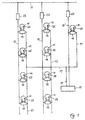
- FIG. 1 shows a schematic embodiment an equipment according to the invention for adjusting Table legs.
- the illustration assumes that each motor 11 a table leg or a double support served.
- Each motor 11 has an individual one Engine electronics 13 equipped.
- the control units 13 are on a supply bus 15 or an individual Supply line 15 'and a common data bus 17 connected.
- An operating element 19 with control electronics is also connected to the data bus 17 and to the power supply 15 ' connected.
- the power supply 15 and 15 ' is one DC power supply. With the power grid 21 connected power supplies 23, for example DC power supply reached.
- the motors 11 are provided with sensors 25, the Signals from the respective engine electronics 13 detected and are processed. With the sensors 25 (it is simplistic only one sensor per motor is shown) the revolutions or the temperature of the motor measured. The relative position one adjustment part to the other, in the example accordingly the height of the table, is due to the revolutions of the Motor in the motor electronics 13 calculated.
- the Motor electronics 13 regulates the speed of the motor with a EMF control by changing the operating voltage on the motor. Other engine speed controls, e.g. with the aid of of the sensors and their temporal pulse variation also useful.
- the control electronics 19 When installing the system, whether at the First installation or a later, new installation, the control electronics 19 speaks one motor after the other with data modulation via data bus 17 on. Each of them responds with a power bill. The Motors registered in this way, or their addresses, are in a non-volatile memory in the control electronics 19 saved. After this registration phase the Initialization phase triggered.
- the Control electronics the operating parameters to the engine electronics transmitted. These operating parameters, like tolerances, Acceleration, braking deceleration, Travel speeds of different speed levels (Manipulated variable change per transmission frequency), maximum permissible adjustment path (difference between the Reference points for the shortest and the longest Column length), reference points for the shortest and the longest column length are stored in non-volatile memories Engine electronics saved. After each received The engine electronics sends a programming command Power receipt.
- Each time the adjustment device is switched on checks the control electronics 19 with a first request the presence of the engines.
- Each engine is individually with a addressed data transmission addressed. That response is supplied by the engine electronics with a power receipt Data bus answered. The absence of an engine is indicated by Absence of a response signal from the corresponding Engine electronics determined. The lack of an answer solves a fault mode. On the other hand, acknowledge all motors the system is ready for operation.
- the height of the table combination will be adjusted Button on control element 19 actuated. Be on the keyboard Direction and driving speed (e.g. by key selection and Key press duration).
- the control electronics 19 then asks voltage-controlled data transmission via data bus 17 die individual motors 11 from.
- This second query checks the Engine operational readiness.
- the engine electronics is through the Query causes the motor temperature to be checked.
- a Any engine overheating is caused by the engine electronics a signal (a power receipt) reported via the data bus.
- a power receipt upon request from the Engine readiness causes the same query is repeated until no more power acknowledgment is transmitted will, i.e. the overheated engine has cooled down.
- the centrally located control electronics transmit then the direction and the via two-pole data bus Drive level (i.e. thanks to a constant time interval transferred vector change the target speed) the dispersed engine electronics. This information is transmitted three times for data security, for example.
- the data format has a motor address (individually for every single one or in general for all together, optional also for groups of motors), the speed level and the direction and finally a check byte.
- Control electronics a provisional absolute position after the others that the motors should reach each.
- This The setpoint is specified by varying the to the motor applied operating voltage by the motor electronics sought.
- the absolute position of the setpoint specification outside of one specified in the engine electronics Tolerance window of the engine is the engine of the Motor electronics approached with an acceleration ramp. Exceeding or falling short of the default will by changing the operating voltage accordingly Motor electronics corrected.
- This correction is made after an algorithm. Should there be a deviation from the setpoint Tolerance limit up to which the motor and Supply resources allow a correction, exceed the motor electronics indicate a current receipt as a signal the control electronics. Whether the correction is possible or is not calculated by the engine electronics.
- the control electronics signal initiates the setpoint specification adapt.
- the control electronics 19 transmits one as a setpoint absolute control value, which is a distance to a Reference point defined. Submitted after 50 milliseconds they increased a certain amount (or lowered) manipulated variable. After another 50 milliseconds manipulated value changed again by the same amount, and so further.
- the amount of each change in The manipulated variable is set by programming the speed steps Are defined. The amount can also increase or decrease be what an acceleration or deceleration of the Driving speed causes.
- Engine electronics count while the motor is rotating, the sensor pulses and compares the meter reading with the target specification. Approaches the counter value of the last default or the reference point, the motor runs to a standstill with a braking ramp delayed.
- the engine electronics make a comparison during the adjustment phase ongoing actual and setpoint. Should the comparison of setpoint and counter value indicate that the actual position is outside the Tolerances is next to the target position, the Motor electronics a power receipt. By arrival of one Acknowledgment of current during the adjustment Control electronics causes the respective increase Correct (decrease) the manipulated value or at the next transmission even an increase in the manipulated variable refrain or the time interval between the To stretch setpoint transmissions.
- the control direction and the speed step are new Are defined.
- To skip a control value increase (reduction) by the saved speed level a command interval of e.g. 50 Skipped milliseconds, so the next command after 100 (at most 150, 200 ...) milliseconds. The the last command issued therefore applies until the Absence of signals from the engine electronics indicates that all motors within a given control value Have reached the tolerance window.
- Adjustment speed comes to the others, e.g. fewer loaded motors beyond the setpoint to be achieved.
- the engine electronics of the too fast engine reduce to this its operating voltage. In this way, synchronism oscillates of the more and less heavily loaded engines.
- the Control electronics When the adjustment device is actuated, the Control electronics the engine readiness before it one Issues driving command. To do this, the engine electronics are queried, whether the engine has overheated. During the adjustment phase the motors on your at regular intervals Readiness for operation (temperature) queried. During the Adjustment phase are continuously actual and target positions saved so that in the event of a line break the current position data is available in the memory.
- Control electronics Undervoltage and subsequently sends the Backup command.
- the current target position saved.
- the engine electronics saves the current actual position of the motor (counter value), which can deviate from the target position.
- data can be transmitted and voltage modulation on the data bus also wireless Transmission e.g. with different radio wave or Infrared wavelengths are used.
- wireless Transmission e.g. with different radio wave or Infrared wavelengths are used.
- ladders are also very easy to install, as the data bus is arbitrary can be branched and also have closed circles can. Every motor electronics only needs one Connection to the data bus.
- the table 31 shown in FIG. 2 with an extension plate 33 has five two double supports 35.36 and 37.38 for the Main plate 39 and a single support 41 for the extension plate 33 on.
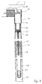
- the head 43 and the table leg 41 shown with the adjustment mechanism in a longitudinal section.
- the head piece 43 is a cast piece and takes the motor 11 with gear 53 and motor electronics 13.
- the drive axle 57 of the motor 11 or the gear 53 is with a Adjustment spindle 59 coupled. This turns into one Adjusting nut 61, which is caused by the rotation of the spindle 59 this is moved up or down.
- the mother is 61 firmly arranged in a support 63.
- the support carries the load the table on the table leg 65.
- the visible outer table leg 41 consists of two tubes.
- the Outer tube 67 includes inner tube 69.
- the two tubes are telescopically slidable and ensure one another the necessary stability of the table leg.
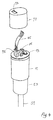
- the motor 11 is in a perspective view in FIG Sketch shown. It can be seen that the Electronics 13 on a circular, the motor cross section corresponding circuit board is arranged. The board is arranged perpendicular to the motor axis and points in the middle a sensor 25 for detecting the engine revolutions, in which the extended axis of the motor rotates. This Arrangement is very space-saving. They are on the board necessary chip arranged and is a plug contact formed, in which the connecting line 45 can be inserted is. The connecting line includes the data bus and the Supply bus.
- the engine electronics 13 is with a Protective cap 71 can be covered. The protective cap 71 has one Opening 73 for piercing the plug 75 of the Connection line 45 on.
Landscapes
- Engineering & Computer Science (AREA)
- Power Engineering (AREA)
- Control Of Multiple Motors (AREA)
Priority Applications (1)
| Application Number | Priority Date | Filing Date | Title |
|---|---|---|---|
| EP98811034A EP0994560A1 (fr) | 1998-10-16 | 1998-10-16 | Méthode et dispositif d'ajustement synchrone des organes mobiles, particulièrement des pieds de table |
Applications Claiming Priority (1)
| Application Number | Priority Date | Filing Date | Title |
|---|---|---|---|
| EP98811034A EP0994560A1 (fr) | 1998-10-16 | 1998-10-16 | Méthode et dispositif d'ajustement synchrone des organes mobiles, particulièrement des pieds de table |
Publications (1)
| Publication Number | Publication Date |
|---|---|
| EP0994560A1 true EP0994560A1 (fr) | 2000-04-19 |
Family
ID=8236389
Family Applications (1)
| Application Number | Title | Priority Date | Filing Date |
|---|---|---|---|
| EP98811034A Withdrawn EP0994560A1 (fr) | 1998-10-16 | 1998-10-16 | Méthode et dispositif d'ajustement synchrone des organes mobiles, particulièrement des pieds de table |
Country Status (1)
| Country | Link |
|---|---|
| EP (1) | EP0994560A1 (fr) |
Cited By (9)
| Publication number | Priority date | Publication date | Assignee | Title |
|---|---|---|---|---|
| WO2006043881A1 (fr) * | 2004-10-19 | 2006-04-27 | Östergrens Elmotor Ab | Meuble verticalement reglable et procede permettant de relever et d'abaisser un meuble verticalement reglable. |
| US7602135B2 (en) | 2002-06-27 | 2009-10-13 | Julius Blum Gesellschaft M.B.H. | Arrangement having at least one movable furniture part |
| DE102008053113A1 (de) * | 2008-10-25 | 2010-05-06 | Brose Fahrzeugteile Gmbh & Co. Kg, Hallstadt | Antriebsanordnung zur motorischen Verstellung eines Verstellelements in einem Kraftfahrzeug |
| WO2011098350A1 (fr) * | 2010-02-12 | 2011-08-18 | BSH Bosch und Siemens Hausgeräte GmbH | Table élévatrice |
| WO2011098354A1 (fr) * | 2010-02-12 | 2011-08-18 | BSH Bosch und Siemens Hausgeräte GmbH | Table élévatrice |
| DE102010046769A1 (de) * | 2010-09-28 | 2012-03-29 | Oelschläger Metalltechnik GmbH | Hubsäuleneinheit zur elektromotorischen Höhenverstellung eines Möbelstücks, insbesondere eines Tisches, elektrisch höhenverstellbares Möbelstück, insbesondere ein Tisch, umfassend selbige sowie Tischanordnung |
| WO2016023700A1 (fr) * | 2014-08-14 | 2016-02-18 | Logicdata Electronic & Software Entwicklungs Gmbh | Prise électrique multiple et système de table à positionnement électrique |
| EP1481203B2 (fr) † | 2002-03-01 | 2016-08-10 | WindowMaster A/S | Procede et systeme de commande d'asservissement d'elements mobiles |
| DE102023122275B4 (de) | 2023-04-27 | 2026-04-30 | Timotion Technology Co., Ltd. | Elektrische schreibtischgestell-struktur |
Citations (6)
| Publication number | Priority date | Publication date | Assignee | Title |
|---|---|---|---|---|
| DE3233788A1 (de) * | 1982-09-11 | 1984-03-15 | Trepel Ag, 6200 Wiesbaden | Steuerungsanlage fuer eine buehnenmaschinerie |
| US4731733A (en) * | 1985-02-06 | 1988-03-15 | Jagenberg Ag | Device for positioning several units that can be moved adjacent to and at a constant distance from one another |
| DE4041087A1 (de) * | 1990-12-21 | 1992-07-02 | Aumueller Aumatic Gmbh | Verfahren und vorrichtung zum motorischen bewegen von grossen fluegeln und lichtkuppeln |
| US5259326A (en) * | 1991-04-17 | 1993-11-09 | Haworth, Inc. | Automated height adjustable work station |
| DE29623428U1 (de) * | 1996-11-28 | 1998-04-23 | Robert Bosch Gmbh, 70469 Stuttgart | Vorrichtung und Steuerung zum koordinierten Betrieb zweier Stellantriebe und zum Datenaustausch |
| WO1998037297A1 (fr) * | 1997-02-20 | 1998-08-27 | Velux Industri A/S | Systeme d'exploitation pour dispositifs a fonctionnement electrique tels que des portes, des fenetres et analogues et unite d'entrainement a utiliser dans ledit systeme |
-
1998
- 1998-10-16 EP EP98811034A patent/EP0994560A1/fr not_active Withdrawn
Patent Citations (6)
| Publication number | Priority date | Publication date | Assignee | Title |
|---|---|---|---|---|
| DE3233788A1 (de) * | 1982-09-11 | 1984-03-15 | Trepel Ag, 6200 Wiesbaden | Steuerungsanlage fuer eine buehnenmaschinerie |
| US4731733A (en) * | 1985-02-06 | 1988-03-15 | Jagenberg Ag | Device for positioning several units that can be moved adjacent to and at a constant distance from one another |
| DE4041087A1 (de) * | 1990-12-21 | 1992-07-02 | Aumueller Aumatic Gmbh | Verfahren und vorrichtung zum motorischen bewegen von grossen fluegeln und lichtkuppeln |
| US5259326A (en) * | 1991-04-17 | 1993-11-09 | Haworth, Inc. | Automated height adjustable work station |
| DE29623428U1 (de) * | 1996-11-28 | 1998-04-23 | Robert Bosch Gmbh, 70469 Stuttgart | Vorrichtung und Steuerung zum koordinierten Betrieb zweier Stellantriebe und zum Datenaustausch |
| WO1998037297A1 (fr) * | 1997-02-20 | 1998-08-27 | Velux Industri A/S | Systeme d'exploitation pour dispositifs a fonctionnement electrique tels que des portes, des fenetres et analogues et unite d'entrainement a utiliser dans ledit systeme |
Cited By (10)
| Publication number | Priority date | Publication date | Assignee | Title |
|---|---|---|---|---|
| EP1481203B2 (fr) † | 2002-03-01 | 2016-08-10 | WindowMaster A/S | Procede et systeme de commande d'asservissement d'elements mobiles |
| US7602135B2 (en) | 2002-06-27 | 2009-10-13 | Julius Blum Gesellschaft M.B.H. | Arrangement having at least one movable furniture part |
| WO2006043881A1 (fr) * | 2004-10-19 | 2006-04-27 | Östergrens Elmotor Ab | Meuble verticalement reglable et procede permettant de relever et d'abaisser un meuble verticalement reglable. |
| DE102008053113A1 (de) * | 2008-10-25 | 2010-05-06 | Brose Fahrzeugteile Gmbh & Co. Kg, Hallstadt | Antriebsanordnung zur motorischen Verstellung eines Verstellelements in einem Kraftfahrzeug |
| US8766563B2 (en) | 2008-10-25 | 2014-07-01 | Brose Fahrzeugteile Gmbh & Co. Kg, Hallstadt | Drive arrangement for the motor-driven adjustment of an adjustable element in a motor vehicle |
| WO2011098350A1 (fr) * | 2010-02-12 | 2011-08-18 | BSH Bosch und Siemens Hausgeräte GmbH | Table élévatrice |
| WO2011098354A1 (fr) * | 2010-02-12 | 2011-08-18 | BSH Bosch und Siemens Hausgeräte GmbH | Table élévatrice |
| DE102010046769A1 (de) * | 2010-09-28 | 2012-03-29 | Oelschläger Metalltechnik GmbH | Hubsäuleneinheit zur elektromotorischen Höhenverstellung eines Möbelstücks, insbesondere eines Tisches, elektrisch höhenverstellbares Möbelstück, insbesondere ein Tisch, umfassend selbige sowie Tischanordnung |
| WO2016023700A1 (fr) * | 2014-08-14 | 2016-02-18 | Logicdata Electronic & Software Entwicklungs Gmbh | Prise électrique multiple et système de table à positionnement électrique |
| DE102023122275B4 (de) | 2023-04-27 | 2026-04-30 | Timotion Technology Co., Ltd. | Elektrische schreibtischgestell-struktur |
Similar Documents
| Publication | Publication Date | Title |
|---|---|---|
| DE60023466T2 (de) | Fernbedienung für eine klimaanlage | |
| EP2819548B1 (fr) | Système de meubles et procédé de commande parallèle d'au moins deux mécanismes de commande à moteur électrique d'un système de meubles | |
| EP2991607B1 (fr) | Table d'opération et procédé de commande d'une table d'opération | |
| EP1312332B1 (fr) | Procedé et dispositif pour télécommander une table d'operation | |
| EP1785119B1 (fr) | Table d'opération | |
| DE60313633T2 (de) | System mit hebesäulen | |
| DE69407024T2 (de) | Steuerung zur Lenkung mit einem Leitdraht für ein von einem Benutzer gelenktes Transportfahrzeug | |
| DE102007031489A1 (de) | Vorrichtung und Verfahren zum Steuern einer Treiberstärke | |
| DE3609690A1 (de) | Sitzeinstellvorrichtung fuer einen mit einer antriebsvorrichtung verstellbaren sitz | |
| DE102015012882A1 (de) | Programmierbare Steuerungen für eine Winde | |
| DE60127828T2 (de) | Kommunikationssystem für eine elektrische einschienenbahn | |
| DE3933288C2 (de) | Vorrichtung zur Steuerung der Stellung des Lenkrades eines Fahrzeugs | |
| DE4212319A1 (de) | Steuervorrichtung | |
| DE102006014897A1 (de) | Schnittstellenvorrichtung und Verfahren zum Vernetzen von älteren Verbraucherelektronikvorrichtungen | |
| EP0743578B1 (fr) | Aménagement de salle blanche | |
| EP3041696B1 (fr) | Système présentant une unité de commande | |
| DE102013105822A1 (de) | Verfahren und Einrichtung zum fernbetätigten Steuern von medizinischen Geräten mittels einer Fernbedienungsvorrichtung | |
| CH713845B1 (de) | Förderanlage zum Fördern von Stückgütern mit verbessertem elektrischem Anschlusssystem. | |
| DE69809195T2 (de) | Ein antriebssystem für elektrisch betätigte vorrichtungen, wie türen, fenster und dergleichen, sowie antriebseinheit zur verwendung bei einem derartigen system | |
| EP2365408A1 (fr) | Colonne d'entraînement dotée d'un stockage de données et meuble dotée d'une telle colonne d'entraînement | |
| DE102004013574B4 (de) | Drahtloser RF-Fernsteuerzonenverbinder und zugehöriges System | |
| EP1136264B1 (fr) | Dispositif et procédé pour commander des zones d'encrage | |
| DE69617866T2 (de) | 12V/24V X-Y-Getriebeschaltvorrichtung | |
| DE60208972T2 (de) | Vorrichtung zur Steuerung elektrischer Leistung | |
| DE3724430C2 (fr) |
Legal Events
| Date | Code | Title | Description |
|---|---|---|---|
| PUAI | Public reference made under article 153(3) epc to a published international application that has entered the european phase |
Free format text: ORIGINAL CODE: 0009012 |
|
| AK | Designated contracting states |
Kind code of ref document: A1 Designated state(s): AT BE CH CY DE DK ES FI FR GB GR IE IT LI LU MC NL PT SE |
|
| AX | Request for extension of the european patent |
Free format text: AL;LT;LV;MK;RO;SI |
|
| AKX | Designation fees paid | ||
| STAA | Information on the status of an ep patent application or granted ep patent |
Free format text: STATUS: THE APPLICATION IS DEEMED TO BE WITHDRAWN |
|
| 18D | Application deemed to be withdrawn |
Effective date: 20001019 |
|
| REG | Reference to a national code |
Ref country code: DE Ref legal event code: 8566 |