EP0994766B1 - Anschlagvorrichtung für eine gehrungssäge - Google Patents
Anschlagvorrichtung für eine gehrungssäge Download PDFInfo
- Publication number
- EP0994766B1 EP0994766B1 EP98939617A EP98939617A EP0994766B1 EP 0994766 B1 EP0994766 B1 EP 0994766B1 EP 98939617 A EP98939617 A EP 98939617A EP 98939617 A EP98939617 A EP 98939617A EP 0994766 B1 EP0994766 B1 EP 0994766B1
- Authority
- EP
- European Patent Office
- Prior art keywords
- stop
- saw
- support
- stop device
- axis
- Prior art date
- Legal status (The legal status is an assumption and is not a legal conclusion. Google has not performed a legal analysis and makes no representation as to the accuracy of the status listed.)
- Expired - Lifetime
Links
- 238000000465 moulding Methods 0.000 claims 1
- 230000008878 coupling Effects 0.000 description 7
- 238000010168 coupling process Methods 0.000 description 7
- 238000005859 coupling reaction Methods 0.000 description 7
- 238000003860 storage Methods 0.000 description 5
- 208000027418 Wounds and injury Diseases 0.000 description 3
- 230000005540 biological transmission Effects 0.000 description 3
- 238000005520 cutting process Methods 0.000 description 3
- 230000006378 damage Effects 0.000 description 3
- 208000014674 injury Diseases 0.000 description 3
- 238000004519 manufacturing process Methods 0.000 description 2
- 230000004323 axial length Effects 0.000 description 1
- 230000000903 blocking effect Effects 0.000 description 1
- 230000000295 complement effect Effects 0.000 description 1
- 238000011109 contamination Methods 0.000 description 1
- 238000006073 displacement reaction Methods 0.000 description 1
- 238000007654 immersion Methods 0.000 description 1
- 238000000034 method Methods 0.000 description 1
- 230000000717 retained effect Effects 0.000 description 1
Images




Classifications
-
- B—PERFORMING OPERATIONS; TRANSPORTING
- B27—WORKING OR PRESERVING WOOD OR SIMILAR MATERIAL; NAILING OR STAPLING MACHINES IN GENERAL
- B27G—ACCESSORY MACHINES OR APPARATUS FOR WORKING WOOD OR SIMILAR MATERIALS; TOOLS FOR WORKING WOOD OR SIMILAR MATERIALS; SAFETY DEVICES FOR WOOD WORKING MACHINES OR TOOLS
- B27G5/00—Machines or devices for working mitre joints with even abutting ends
- B27G5/02—Machines or devices for working mitre joints with even abutting ends for sawing mitre joints; Mitre boxes
- B27G5/023—Machines or devices for working mitre joints with even abutting ends for sawing mitre joints; Mitre boxes the mitre angle being adjusted by positioning a workpiece relative to a fixed saw
-
- B—PERFORMING OPERATIONS; TRANSPORTING
- B27—WORKING OR PRESERVING WOOD OR SIMILAR MATERIAL; NAILING OR STAPLING MACHINES IN GENERAL
- B27B—SAWS FOR WOOD OR SIMILAR MATERIAL; COMPONENTS OR ACCESSORIES THEREFOR
- B27B27/00—Guide fences or stops for timber in saw mills or sawing machines; Measuring equipment thereon
- B27B27/06—Guide fences or stops for timber in saw mills or sawing machines; Measuring equipment thereon arranged angularly with respect to the plane of the saw blade, e.g. for mitring
-
- B—PERFORMING OPERATIONS; TRANSPORTING
- B27—WORKING OR PRESERVING WOOD OR SIMILAR MATERIAL; NAILING OR STAPLING MACHINES IN GENERAL
- B27B—SAWS FOR WOOD OR SIMILAR MATERIAL; COMPONENTS OR ACCESSORIES THEREFOR
- B27B27/00—Guide fences or stops for timber in saw mills or sawing machines; Measuring equipment thereon
- B27B27/08—Guide fences or stops for timber in saw mills or sawing machines; Measuring equipment thereon arranged adjustably, not limited to only one of the groups B27B27/02 - B27B27/06
-
- B—PERFORMING OPERATIONS; TRANSPORTING
- B27—WORKING OR PRESERVING WOOD OR SIMILAR MATERIAL; NAILING OR STAPLING MACHINES IN GENERAL
- B27B—SAWS FOR WOOD OR SIMILAR MATERIAL; COMPONENTS OR ACCESSORIES THEREFOR
- B27B27/00—Guide fences or stops for timber in saw mills or sawing machines; Measuring equipment thereon
- B27B27/10—Devices for moving or adjusting the guide fences or stops
Definitions
- the invention relates to a stop device for a miter saw according to the preamble of claim 1 and a miter saw with a stop device according to the invention.
- the known stop devices are with a swiveling saw combined, which when swiveling an angle scale on a support of Stop device sweeps.
- a baseboard for Sawing the corner of a room first becomes the angle of the corner measured, then set the saw to half the angle, and then miter sawn the corresponding bar against the stop. The saw is then moved in by the measured angle then pivoted the opposite half of the pad sawn the complementary skirting board.
- the invention is therefore based on the object of a stop device Provide initially mentioned type and a miter saw that is simple and are safe to use, ensure precise miter cuts, and are small and easy to implement.
- This object is achieved according to the invention solved by a stop device with the features of claim 1 and a miter saw with the features of claim 15.
- Special Embodiments of the invention are disclosed in the subclaims.
- a stop device in a stop device according to claim 1 is advantageous in that the provision of a common pivot axis of the cutting area of the saw on the bisector regardless of the miter angle set is stationary.
- the immersion depth of, for example, a saw blade in the support is only determined by the workpiece to be sawn and is especially regardless of the set miter angle. This does not increase only operational safety, but also reduces the size and mass the stop device or the associated miter saw.
- the special embodiment of the invention according to claim 2 has the Advantage that in relation to the common axis in the radial direction compared to a stop block slidable the distance the stop rail to the bisector or to the common axis according to the set miter angle and / or the one to be sawn Workpiece can be adjusted. This initially makes it more precise Guidance and thus a more precise miter cut achieved. Beyond that also increases the operational safety of the stop device and minimizes the risk of injury. A is also particularly conceivable automatic movement of the stop rail in relation to the stop block depending on the set miter angle by a mechanical Coupling the swiveling movement with a displacement movement of the Stop rail in relation to the stop block.
- the special embodiment of the invention according to claim 3 has the Advantage that the sling in the position of the set Miter angles are fixable.
- the finding can in particular by Clamping the sling to the support or by blocking the Swivel mechanism, for example, take place directly on the common Axis.
- the corner angle to be sawn by means of a The cuddle can be removed, then the cuddle placed the edition and brought the attacks into contact with the cuddle and can be determined.
- the special embodiment according to claim 4 has the advantage that a Such swivel arm guide of the sling with low overall height and realizes low mass. In addition, it shows little moving parts and therefore only a low mass inertia when adjusting. In addition, a hermetic seal is not necessary and relatively simple constructive means a little mechanical play of the Stop device accessible. By one in relation to the bisecting line of the mirror image is the number of required parts and thus the manufacturing costs of the device reduced. The arrangement is quiet when adjusting, simply in Assembly and service as well as maintenance-free.
- the special embodiment of the invention according to claim 5 has the Advantage that the direct guidance of the joint along the Bisect the number of required parts below the support is further reduced with the associated aforementioned Advantages.
- the pivot levers are preferably according to claim 6 the common axis cranked or bent around, reducing the overall size and mass is further reduced.
- the guidance of the joint can either be according to Claim 7 by a sled-like guide on a guide rod take place or according to claim 8 by guiding a pin or Nutsteins in a in the bottom of the edition and on the bisector aligned groove.
- the special embodiment of the invention according to claim 9 has the Advantage that the mechanical coupling by means of two swivel plates A particularly precise guidance is guaranteed, which also has high torques can transmit.
- the special embodiment of the invention according to claim 10 has the Advantage that the combination of a gear connection and a Another gear connection ensures particularly precise guidance of the stops is guaranteed during the pivoting movement.
- the device according to Claim 11 has the advantage that by using a Belt connection a permanently reliable and inexpensive guidance of the Sling is guaranteed and in particular the use of a Timing belt further improves the accuracy of the guide.
- the special embodiment of the invention according to claim 12 has the Advantage that by using three appropriately arranged Bevel gears reverse the direction of rotation of the swivel movement of the two Slings with low mechanical play can be realized.
- the bevel gears can also be designed as friction wheels, preferably it is however, according to the embodiment according to claim 13 around conical Gears, which allows the transmission of large torques at the same time precise guidance is guaranteed.
- the special embodiment of the invention according to claim 14 has the Advantage that such a rope, belt or chain guide is constructive is particularly easy to implement.
- the management of the trains is essential along the semicircular projections. This will make one Guaranteed guidance of the sling gear in both swivel directions. By wrapping the pulleys around at least 90 ° guarantees a particularly precise guidance of the lifting gear.
- the special embodiment according to claim 17 has the advantage that with such a miter saw can also be sawn strips, the end of which be mitered on two surfaces.
- FIG. 1 shows a top view of a first embodiment of the Invention.
- a base plate 101 serving as a support a first stop rail 103 and a second stop rail 104, respectively adjustably attached to a stop block 105 or 106.
- the two Stop blocks 105 and 106 are in a first and a second Guide slot 107 and 108 movable in the base plate 101 and through the underside of the base plate 101 arranged and on a common Axis 113 articulated pivot arms 111 and 112 guided.
- the common Axis 113 is in any pivot position of the pivot arms 111, 112 the dotted extensions of the two the workpiece facing stop surfaces of the stop rails 103, 104 or defined the intersection of these extensions.
- the two guide slots 107, 108 each extend along an almost semicircular line, whereby the two semicircular lines open to each other and symmetrical to the dash-dotted angle bisectors 160 are arranged.
- the two stop blocks 105, 106 are shown in the Exemplary embodiment using locking wing screws 128 with the associated - not shown - swivel arms connected on the underside.
- the stop blocks 105, 106 clamped on the base plate 101 and thus determined.
- the stop blocks 105, 106 along the guide slots 107, 108 pivotable movable.
- the two stop rails 103, 104 are in their Longitudinal direction and parallel to the base plate 101 relative to the stop blocks 105, 106 adjustable, for example via a tongue and groove guide Dovetail cross section and are releasably connected to them, for example by thumbscrews 123.
- the contact surfaces of the Stop rails 103, 104 are designed according to the prior art, and can in particular have strip or grid-shaped grooves to a to ensure safe and level contact of the workpieces to be sawn.
- the stop device according to the invention forms in a special Embodiment of the invention a part of a miter saw, for example a cross-cut or ledge saw.
- a saw preferably one Electric motor saw 132.
- the pivot axis of this saw 132 runs parallel to Base plate 101 and perpendicular to the bisector 160.
- the saw 132 has a saw blade which is aligned with the bisector 160, and whose axis of rotation runs parallel to the pivot axis of the saw 132.
- FIG. 2A shows a bottom view of the first exemplary embodiment in FIG. 1.
- the common axis 113 is at the center of the arranged two semicircles, along which the first and second Guide slot 107, 108 extends.
- the bisector 160 has a first end on the second swivel arm 112 second pivot lever 122 articulated.
- the two second ends of the first or second pivot lever 121 or 122 are by means of a Sliding blocks 124 in a groove 155 aligned with the bisector 160 guided joint 125 connected together.
- the two swivel levers 121, 122 are preferably curved in their longitudinal direction in order to every possible adjustable miter angle a reaching around to ensure common axis 113.
- FIG. 2B shows a perspective bottom view of a second one Embodiment of the invention.
- the base plate 201 faces symmetrical on both sides of the bisector, not shown each two concentric, radially spaced and almost semicircular Guide slots 207, 207 'and 208, 208'.
- the (not shown) on the Top of the base plate 201 attached slings are over the guide slots 207, 207 'and 208, 208' with the first and second, respectively Swivel arm 211 and 212 connected, which about the common axis 213 in different planes parallel to the base plate 201 are articulated.
- the attachment of the sling, in particular the sling blocks, to two radially spaced points on the pivot arms 211 and 212 respectively the two radially spaced guide slots 207, 207 'and 208, 208' improves the exact radial alignment of the lifting gear with respect to the common axis 213.
- the articulated with the swivel arms 211, 212 connected pivot levers 221, 222 are connected by a carriage 226 forming joint connected to each other, which has a bore, by the one guide bar 227 aligned with the bisector passes, which guides the carriage 226.
- two parallel guide rods 227 provided, each through a bore in the carriage 226th step through.
- a Locking lever 228 to be operated Via one of an end face of the stop device manually by means of a Locking lever 228 to be operated is one with respect to the common axis 213 radially movable locking device 229 in contact brought with the pivot axis 230 to the position of the pivot arms 211, 212 or the one on top of the support 201 in connection to fix standing slings.
- the pivoting movement of the Locking lever 228 is known from the prior art Deflection means in a radial with respect to the common axis 213 Movement of the locking device 229 implemented.
- the pivot levers 221, 222 can not only be curved in an arc be executed, but show any form that is suitable under Taking into account the adjustable miter angle, changing the grip to ensure common pivot axis 230.
- the pivot levers 221, 222 may also be cranked or in the form of a have elongated stylized "S".
- a major advantage of this preferred embodiment is that the stop device both on the top and on the bottom of the edition 201 is mirrored to the bisector of the angle and thus identical parts can be used for the left and right half. By are the reduction in the number of different parts required the manufacturing and storage costs of such a stop device significantly reduced.
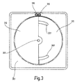
- FIG. 3 shows a bottom view of a third exemplary embodiment, which is designed on the upper side of the base plate 301 like the first exemplary embodiment.
- each stop block is detachably connected to a first or second swivel plate 311 or 312.
- the two swivel plates 311, 312 are around.
- a common axis 313 is mounted, but at different heights, that is, in different planes parallel to the base plate 301.
- the toothed disks 311, 312 are not designed as full circles, but rather, for example, as semicircles , the diameter of which is identical.
- the first swivel plate 311, which is mounted closer to the base plate 301 preferably has at least one slot 307 through which the connection between the second swivel plate 312 and its stop block is guided.
- the swivel plates 311, 312 have a along their outer circumferential line radially protruding teeth. Grip with this interlocking the swivel plates 311 and 312 in each one at this point Gear 315 or 316 arranged circumferentially.
- the two gears 315, 316 are of the same diameter, right next to each other arranged and interlock thanks to the corresponding axial length, whereby as in the first embodiment, a mechanical coupling is realized between the slings. Due to the chosen arrangement of the Swivel discs 311, 312 and the gears 315, 316 can be the Set the lifting gear at an angle to each other while at the same time being stationary the bisector.
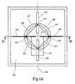
- FIG. 4A shows a bottom view of a fourth exemplary embodiment in FIG a 180 ° position of the stop rails 403, 404 about the common axis 413.
- the two stop rails 403, 404 are via guide slots 407, 408 in the base plate 401, each with a first end of two, below and push rods 452 and 453 arranged parallel to the base plate 401 connected.
- the connection is preferably made via a swivel joint 450 and 451, which is a combined push / swivel movement of the Push rods 452, 453 parallel to the plane of the base plate 401 allows.
- the two second ends of the two push rods 452, 453 are over one another hinge 454 connected to each other, which in a groove 455 in the Bottom of the base plate 401 is guided.
- the groove 455 is on the Bisector 460 aligned.
- the two push rods 452, 453 have an identical length and preferably form equilateral Leg of a triangle, the third side of which by the imaginary Connection line between the two pivots 450, 451 is formed.
- Two push rods 456 and 457 are connected to the two stop rails 403, 404 via further swivel joints which are on the same axis as the swivel joints 450, 451, and are connected to one another at their ends facing away from the stop rails 403, 404 via a further swivel joint 454 ' are connected, which is also guided in a groove 455 'in the underside of the base plate 401 along the bisector 460.
- all push rods 452, 453, 456 and 457 are of identical length. However, a different length of the push rods is also possible, the push rods 452, 453 and 456, 457 each having the same length in pairs.
- FIG. 4B shows a bottom view of the fourth exemplary embodiment in one 90 ° position of the two stop rails 403, 404.
- the swivel joints 454 or 454 ' have their position in the grooves 455 assigned to them or 455 'changed.
- the associated push rods 452, 453 or 456, 457 can be adjusted Angular range for the stop rails 403, 404 are limited.
- Figure 4C shows a schematic and z. T. cut open side view of the fourth embodiment along the section line IVc-IVc of Figure 4A.
- the stop rails 403 and 404 engage over guide slots 407 and 408 on the underside of the base plate 401.
- Rotary joints 450 and 451 are the push rods 452 and 453 with the Stop rails 403 and 404 connected. That of the stops 403 and 404 opposite ends of the push rods 452 and 453 are with a Not shown pivot 454 on a common, perpendicular to Base plate 401 aligned pivot axis 458 attached, which in the Groove 455 is guided along the bisector.
- the illustrated embodiments of the third embodiment are deliberately shown without swivel arms attached to the underside. At these versions, the storage for the pivoting movement on the Top of the base plate 401 take place.
- the storage for the pivoting movement on the Top of the base plate 401 take place.
- swivel arms on the underside the stops are connected to the first ends of the push rods 450, 451, 456 and 457 are articulated.
- Such an execution has the Advantage that the storage of the swivel arms and thus the storage for the pivoting movement of the stop rails on the underside of the support 401 can be made and thus protected against contamination is.
- FIG. 5A shows a bottom view of a fifth exemplary embodiment, in which the two stop rails 503, 504 are each connected via guide slots 507, 508 to a swivel arm 511 or 512 which can be rotated about a common axis 513.
- the first swivel arm 511 is connected below the base plate 501 to a first axis 561 which is rotatable about the common axis 513 and to which a first gear 562 is applied, which engages in a second gear 563 which is applied to an auxiliary axis 564 which is parallel to the first axis 561.
- the auxiliary axis has a first pulley 566 spaced axially from the second gear 563, which is connected via a belt 567 to a second pulley 568, which is mounted on a hollow axis which is arranged coaxially with the first axis 561 and surrounds it.
- the belt connection causes the auxiliary axis 564 and the hollow axis 565 to rotate in the same direction.
- the transmission ratio of the belt drive is 1: 1.
- the belt connection is preferably designed as a toothed belt connection, ie the two belt pulleys are toothed belt pulleys and the belt is a toothed belt.
- the order of gear and belt connection within the mechanical coupling can also be reversed; the only essential thing is that the gear connection ensures a reversal of the direction of rotation caused by the belt connection is retained.
- the bearing of the first axis 561, the auxiliary axis 564 and the hollow axis are perpendicular to the base plate 501 and preferably on the bisector 560.
- Figure 5B shows a schematic and z. T. cut open side view of the fifth embodiment along the section line Vb-Vb of Figure 5A.
- the first stop rail 503 is connected to the guide slot 507 Swivel arm 511 connected to the one about the common axis 513 rotatable first axis 561 on which the first gear 562 is applied.
- Arrows 503 'each show the direction of pivoting Stop rail 503, the first axis 561 and the first gear 562.
- the gear connection between the gears 562 and 563 provides one Swing direction reversal, which of the not shown in Figure 5B second gear 563, which on the auxiliary axis 564, also not shown sits, by means of the belt 567 and the pulley 568 on the hollow axis 565 is transmitted.
- With the hollow axis 565 is the through the Guide slot 508 through swing arm 512 the second Stop rail 504 connected.
- Arrows 504 show the pivot direction the pulley 568 or the stop rail 504.
- FIG. 5C shows a perspective view of the mechanical coupling of the fifth embodiment.
- the transmission of the Swiveling movement of the sling means over the swivel arm 511 to the first Axis 561 and the swivel direction reversal via gear connection 562, 563 on the auxiliary axis 564 and via the toothed belt connection 566, 567, 568 back to the hollow axis 565 arranged coaxially to the first axis 561, with which the second swivel arm 512 is connected to.
- the storage of the first axis 561 and the auxiliary axis 564 by means of slide or ball bearings 569 shown.
- Figure 6 shows a schematic and z. T. cut open side view of a sixth embodiment.
- the first stop rail 603 via the guide slot 607 with the one below the base plate 601 about the common axis 613 rotatable first Swivel arm 611 connected.
- the swivel arm 611 has a first axis 670 connected to which a first conical gear 671 is applied.
- the first axis 670 is supported in the underside of the base plate 601 and in the bottom surface by means of a slide or ball bearing 669 in each case.
- the first conical gear 671 meshes with a second conical gear 672 which is mounted on an auxiliary axis 673 which is supported in the side wall of the stop device by a slide or ball bearing.
- the auxiliary axis 673 of the second conical gear 672 forms an angle of 90 ° with the first axis 670.
- the second conical gear 672 also meshes with a third conical gear 674, which is seated on a hollow axis 675 which is arranged coaxially with the first axis 670 and surrounds it.
- the second swivel arm 612 and thus the second stop rail 604 are connected to the hollow axis 675 via the guide slot 608.
- FIG. 7A shows a bottom view of a seventh exemplary embodiment in one 180 ° position of the stop rails 703, 704, the fastening bolts 781, 782, which via guide slots 707, 708 on the underside of the Reach base plate 701 through.
- the Fastening bolts 781, 782 two cables 783, 784 fastened and from each other spaced-apart deflection rollers 785, which can be rotated about deflection axes 787, 788, 786 attached.
- the two pulleys 785, 786 and the two Fastening bolts 781, 782 ideally lie on a circular line the common axis 713.
- the two are Deflection rollers 785, 786 on the bisector 760 between the ends of the two almost semicircular guide slots 707, 708. Furthermore are on the underside of the base plate 701 along the guide slots 707, 708 almost semicircular projections 791, 792, one circular guidance of the cables 783, 784 serve.
- the first cable 783 is on the first fastening bolt 781 of the first Stop rail 703 attached.
- the 783 cable pull runs from there Quarter-turn counterclockwise along the first projection 791 to to the first pulley 785.
- the first cable 783 runs almost along the Bisector 760 to the second deflection roller 786.
- the first cable 783 runs through 90 ° of the second deflection roller 786 a quarter turn clockwise along the second projection 792 and is finally on the second mounting bolt 782 of the second Stop rail 704 attached.
- the second cable 784 runs from the first fastening bolt 781 a quarter turn clockwise along the first projection 791 to to the second pulley 786, then almost along the Bisector 760 to the first deflection roller 785 and after approximately 90 ° wrap a quarter circle counterclockwise along the second projection 792 to the second fastening bolt 782.
- the wrapping of the pulleys 785, 786 through the cables 791, 792 can be reversed by changing the wrap direction preferably also be more than 90 °, for example 270 °.
- FIG. 7B shows a bottom view of the seventh exemplary embodiment in one 90 ° position of the two stop rails 703, 704 about the common axis 713.
- the first cable pull 783 runs from the first fastening bolt 781 first a three-eighth turn counterclockwise to first pulley 785, then almost along the bisector 760 to the second guide roller 786 and then one-eighth turn to the second fastening bolt 782.
- the second cable runs accordingly 784 first one clockwise turn to the second Fastening roller 786, then almost along the bisector 760 to the first pulley 785 and then a three-eighth turn counterclockwise to the second fastening bolt 782.
- a rope or chain hoist can also be used.
- FIG. 7C shows a side view rotated by 180 ° in the plane of the drawing a section of Figure 7A along the line Vllc-Vllc of Figure 7A.
- a view of the second deflection roller 786 is shown, that shown in FIG Case is in two parts and two pulleys 786, 786 'on the common Deflection axis 788.
- the first cable pull 783 runs in the second Cantilever 792 in a track 783 'assigned to it.
- the first cable 783 assigned deflection roller also has a corresponding circumferential groove for receiving and guiding the 783 cable.
- the second cable 784 runs in a track 784 ′ assigned to it in FIG the first projection 791.
- the one assigned to the second cable 784 Deflection roller 786 ' also has a circumferential groove for receiving the Cable 784.
- the two are also in FIG. 7C Stop rails 703, 704 shown above the base plate as well the guide slots 707, 708 assigned to these stop rails 703, 704 indicated by dashed lines.
Landscapes
- Life Sciences & Earth Sciences (AREA)
- Engineering & Computer Science (AREA)
- Mechanical Engineering (AREA)
- Wood Science & Technology (AREA)
- Forests & Forestry (AREA)
- Transmission Devices (AREA)
- Sawing (AREA)
- Processing Of Stones Or Stones Resemblance Materials (AREA)
- Earth Drilling (AREA)
- Dowels (AREA)
- Piles And Underground Anchors (AREA)
Description
- Fig. 1
- zeigt eine Aufsicht auf ein erstes Ausführungsbeispiel,
- Fig. 2A
- zeigt eine Untersicht des ersten Ausführungsbeispiels,
- Fig. 2B
- zeigt eine perspektivische Untersicht eines zweiten Ausführungsbeispiels,
- Fig. 3
- zeigt eine Untersicht eines dritten Ausführungsbeispiels,
- Fig. 4A
- zeigt eine Untersicht eines vierten Ausführungsbeispiels in einer 180°-Position der Anschlagschienen,
- Fig. 4B
- zeigt eine Untersicht des vierten Ausführungsbeispiels in einer 90°-Position der Anschlagschienen,
- Fig. 4C
- zeigt eine z. T. aufgeschnittene Seitenansicht des vierten Ausführungsbeispiels,
- Fig. 5A
- zeigt eine Untersicht eines fünften Ausführungsbeispiels,
- Fig. 5B
- zeigt eine z. T. aufgeschnittene Seitenansicht des fünften Ausführungsbeispiels,
- Fig. 5C
- zeigt eine perspektivische Ansicht der mechanischen Kopplung des fünften Ausführungsbeispiels,
- Fig. 6
- zeigt eine z. T. aufgeschnittene Seitenansicht eines sechsten Ausführungsbeispiels,
- Fig. 7A
- zeigt eine Untersicht eines siebten Ausführungsbeispiels in einer 180°-Position der Anschlagschienen,
- Fig. 7B
- zeigt eine Untersicht des siebten Ausführungsbeispiels in einer 90°-Position der Anschlagschienen, und
- Fig. 7C
- zeigt eine Seitenansicht eines Ausschnittes der Fig. 7A.
Die beiden Schwenkscheiben 311, 312 sind um. eine gemeinsame Achse 313 gelagert, aber in verschiedenen Höhen, also in verschiedenen Ebenen parallel zur Grundplatte 301. Um Raum für eine Schwenkbewegung bei gleichzeitigem Mitführen der Anschlagblöcke zur Verfügung zu haben, sind die Zahnscheiben 311, 312 nicht als Vollkreise ausgeführt, sondern beispielsweise als Halbkreise, wobei deren Durchmesser identisch ist. Die näher zur Grundplatte 301 gelagerte erste Schwenkscheibe 311 weist vorzugsweise wenigstens einen Schlitz 307 auf, durch den die Verbindung zwischen der zweiten Schwenkscheibe 312 und deren Anschlagblock geführt ist.
Im dargestellten Ausführungsbeispiel sind alle Schubstangen 452, 453, 456 und 457 von identischer Länge. Möglich ist allerdings auch eine unterschiedliche Länge der Schubstangen, wobei die Schubstangen 452, 453 und 456, 457 jeweils paarweise in ihrer Länge identisch sind.
Das Übersetzungsverhältnis des Riemenantriebs beträgt 1:1. Vorzugsweise ist die Riemenverbindung als Zahnriemenverbindung ausgeführt, d. h. die beiden Riemenscheiben sind Zahnriemenscheiben und der Riemen ist ein Zahnriemen.
Das erste kegelförmige Zahnrad 671 greift in ein zweites kegelförmiges Zahnrad 672 ein, das auf einer Hilfsachse 673 aufgebracht ist, die in der Seitenwand der Anschlagvorrichtung durch ein Gleit- oder Kugellager gelagert ist. Die Hilfsachse 673 des zweiten kegelförmigen Zahnrades 672 schließt mit der ersten Achse 670 einen Winkel von 90° ein. Das zweite kegelförmige Zahnrad 672 greift außerdem in ein drittes kegelförmiges Zahnrad 674 ein, das auf einer Hohlachse 675 sitzt, die koaxial zu der ersten Achse 670 angeordnet ist und diese umschließt. Mit der Hohlachse 675 ist der zweite Schwenkarm 612 und damit über den Führungsschlitz 608 die zweite Anschlagschiene 604 verbunden.
Claims (10)
- Anschlagvorrichtung für eine Gehrungssäge mit zwei in einer durch eine Auflage (101) für ein Werkstück gebildeten Ebene um eine gemeinsame Achse (113) schwenkbaren Anschlagmitteln (103, 105, 104, 106), die derart miteinander gekoppelt sind, daß eine Winkelhalbierende (160) des durch die Anschlagmittel (103, 105, 104, 106) eingeschlossenen Winkels stets ortsfest zur Auflage (101) ist und die gemeinsame Achse (113) in jeder Schwenkposition der Anschlagmittel (103, 105, 104, 106) Verlängerungen von dem Werkstück zugewandten Anschlagflächen der Anschlagmittel (103, 105, 104, 106) schneidet, wobei die Anschlagmittel (103, 105, 104, 106) mit unterhalb der Auflage um die gemeinsame Achse schwenkbaren Schwenkarmen (121, 122) verbunden sind, dadurch gekennzeichnet, daß an jedem Schwenkarm (111, 112) ein erstes Ende eines Schwenkhebels (121, 122) angelenkt ist und daß die zweiten Enden der Schwenkhebel (121, 122) durch ein Gelenk (125) miteinander verbunden und unterhalb der Auflage in einer auf die Winkelhalbierende (160) ausgerichteten Führung (124, 155) geführt sind.
- Anschlagvorrichtung nach Anspruch 1, dadurch gekennzeichnet, daß die Anschlagmittel (103, 105, 104, 106) einen Anschlagblock (105, 106) und eine an diesem verschiebbar angebrachte Anschlagschiene (103, 104) aufweisen.
- Anschlagvorrichtung nach Anspruch 1 oder 2, gekennzeichnet durch Mittel (128; 228, 129) zum Feststellen der Anschlagmittel (103, 105, 104, 106).
- Anschlagvorrichtung nach einem der Ansprüche 1 bis 3, dadurch gekennzeichnet, daß die Anschlagmittel über Führungsschlitze (107, 108) in der Auflage (101) mit den Schwenkarmen (111, 112) verbunden sind.
- Anschlagvorrichtung nach einem der Ansprüche 1 bis 4, dadurch gekennzeichnet, daß die Schwenkhebel (121, 122) um die gemeinsame Achse (112) herum gekröpft oder gebogen sind.
- Anschlagvorrichtung nach einem der Ansprüche 1 bis 5, dadurch gekennzeichnet, daß die Führung einen das Gelenk bildenden Schlitten (226) aufweist, der mittels einer Führungsstange (227) geführt ist.
- Anschlagvorrichtung nach einem der Ansprüche 1 bis 5, dadurch gekennzeichnet, daß die Führung (124, 155) eine Nut (155) und einen darin geführten und an dem Gelenk (125) angebrachten Zapfen oder Nutstein (124) aufweist.
- Gehrungssäge, insbesondere Kappsäge oder Leistensäge, mit einer Anschlagvorrichtung nach einem der Ansprüche 1 bis 7, wobei eine schwenkbar zur Auflage (101) gelagerte und auf die Winkelhalbierende (160) ausgerichtete Säge (132), vorgesehen ist.
- Gehrungssäge nach Anspruch 8, dadurch gekennzeichnet, daß die Schwenkachse der Säge parallel zur Auflage (101) ist und mit der Winkelhalbierenden (160) einen Winkel von 90° einschließt.
- Gehrungssäge nach Anspruch 8 oder 9, dadurch gekennzeichnet, daß die Säge (132) um eine parallel zur Auflage (101) und zur Winkelhalbierenden (160) ausgerichtete Kippachse verkippbar ist.
Applications Claiming Priority (3)
| Application Number | Priority Date | Filing Date | Title |
|---|---|---|---|
| DE19729552 | 1997-07-10 | ||
| DE19729552A DE19729552A1 (de) | 1997-07-10 | 1997-07-10 | Anschlagvorrichtung für Gehrungssäge |
| PCT/EP1998/004147 WO1999002317A1 (de) | 1997-07-10 | 1998-07-04 | Anschlagvorrichtung für eine gehrungssäge |
Publications (2)
| Publication Number | Publication Date |
|---|---|
| EP0994766A1 EP0994766A1 (de) | 2000-04-26 |
| EP0994766B1 true EP0994766B1 (de) | 2001-07-18 |
Family
ID=7835276
Family Applications (1)
| Application Number | Title | Priority Date | Filing Date |
|---|---|---|---|
| EP98939617A Expired - Lifetime EP0994766B1 (de) | 1997-07-10 | 1998-07-04 | Anschlagvorrichtung für eine gehrungssäge |
Country Status (4)
| Country | Link |
|---|---|
| EP (1) | EP0994766B1 (de) |
| AT (1) | ATE203195T1 (de) |
| DE (2) | DE19729552A1 (de) |
| WO (1) | WO1999002317A1 (de) |
Cited By (1)
| Publication number | Priority date | Publication date | Assignee | Title |
|---|---|---|---|---|
| DE202007003439U1 (de) | 2007-03-06 | 2008-07-17 | Metabowerke Gmbh | Winkelschmiege |
Families Citing this family (9)
| Publication number | Priority date | Publication date | Assignee | Title |
|---|---|---|---|---|
| JP3676928B2 (ja) * | 1998-08-11 | 2005-07-27 | 株式会社マキタ | バイス装置のフェンス |
| DE19909616A1 (de) * | 1999-03-05 | 2000-09-14 | Reich Maschf Gmbh Karl | Anschlagvorrichtung für eine Säge, insbesondere für eine Gehrungssäge, sowie eine Säge mit einer solchen Anschlagvorrichtung |
| DE20203147U1 (de) * | 2002-02-28 | 2002-06-06 | Elektra Beckum Ag, 49716 Meppen | Sägevorrichtung |
| GB2389333A (en) * | 2002-06-08 | 2003-12-10 | Black & Decker Inc | Mitre saw with adjustable fence |
| DE10253011A1 (de) * | 2002-11-14 | 2004-06-09 | Wilhelm Altendorf Gmbh & Co. Kg | Gehrungsanschlag |
| DE102006055209A1 (de) * | 2006-11-21 | 2008-06-05 | Herbert Schenk | Verfahren zum passgenauen Zuschneiden von Leisten und Trennvorrichtung zur Durchführung des Verfahrens |
| US8621970B2 (en) | 2011-01-03 | 2014-01-07 | Robert Bosch Gmbh | Miter saw with adjustable fence |
| DE102012212932B4 (de) | 2012-07-24 | 2026-01-15 | Robert Bosch Gmbh | Oszillationswerkzeugmaschinensägetisch |
| DE102014105103A1 (de) | 2014-04-10 | 2015-10-15 | Metabowerke Gmbh | Anschlagvorrichtung |
Family Cites Families (8)
| Publication number | Priority date | Publication date | Assignee | Title |
|---|---|---|---|---|
| GB191225792A (en) * | 1912-11-09 | 1913-11-10 | Pettingell Machine Company | Improvements in Saw Table Guides. |
| DE299296C (de) * | 1914-03-28 | |||
| US1704747A (en) * | 1927-01-03 | 1929-03-12 | Kopecky Anton | Miter box |
| US3901498A (en) * | 1974-03-11 | 1975-08-26 | Edward P Novak | Miter table |
| US4328728A (en) * | 1980-04-29 | 1982-05-11 | Hirsh Company | Apparatus for effecting a miter cut with a portable circular saw |
| US5473821A (en) * | 1993-03-29 | 1995-12-12 | Dimarco; John | Parallelogram device for setting mitering saws |
| US5402701A (en) * | 1993-12-16 | 1995-04-04 | Ingram; Stanley J. | Dual angle miter and gauge apparatus |
| US5755148A (en) * | 1995-07-07 | 1998-05-26 | Black & Decker Inc. | Adjustable fence for a compound miter saw |
-
1997
- 1997-07-10 DE DE19729552A patent/DE19729552A1/de not_active Withdrawn
-
1998
- 1998-07-04 DE DE59801049T patent/DE59801049D1/de not_active Expired - Lifetime
- 1998-07-04 WO PCT/EP1998/004147 patent/WO1999002317A1/de not_active Ceased
- 1998-07-04 EP EP98939617A patent/EP0994766B1/de not_active Expired - Lifetime
- 1998-07-04 AT AT98939617T patent/ATE203195T1/de not_active IP Right Cessation
Cited By (2)
| Publication number | Priority date | Publication date | Assignee | Title |
|---|---|---|---|---|
| DE202007003439U1 (de) | 2007-03-06 | 2008-07-17 | Metabowerke Gmbh | Winkelschmiege |
| EP1967816A1 (de) | 2007-03-06 | 2008-09-10 | Metabowerke GmbH | Winkelschmiege |
Also Published As
| Publication number | Publication date |
|---|---|
| DE59801049D1 (de) | 2001-08-23 |
| WO1999002317A1 (de) | 1999-01-21 |
| ATE203195T1 (de) | 2001-08-15 |
| DE19729552A1 (de) | 1999-01-14 |
| EP0994766A1 (de) | 2000-04-26 |
Similar Documents
| Publication | Publication Date | Title |
|---|---|---|
| EP0242733B2 (de) | Sägeeinrichtung | |
| EP0994766B1 (de) | Anschlagvorrichtung für eine gehrungssäge | |
| EP1839826B1 (de) | Kreissägemaschine mit Einspannvorrichtung für ein Kreissägeblatt | |
| EP0925893B1 (de) | Mauerschlitzgerät mit verstellbarem Schnittiefenfenanschalg | |
| DE69303444T2 (de) | Sägetisch mit lösbarer Arretiervorrichtung | |
| DE3744716C2 (de) | Tischkreissäge | |
| EP1886752A1 (de) | Kapp- und Gehrungssäge mit einem Drehtisch | |
| DE4225596A1 (de) | Spannvorrichtung | |
| EP0268096A1 (de) | Kreissägemaschine | |
| DE3347920A1 (de) | Saegeeinrichtung | |
| DE19753887A1 (de) | Holzbearbeitungsmaschine | |
| DE3918710C2 (de) | Gehrungssäge für Glashalteleisten | |
| DE3604411A1 (de) | Mehrzweck-holzbearbeitungsmaschine | |
| DE3430814A1 (de) | Schraubstock | |
| DE10234818B4 (de) | Auflagetisch für eine Trennsäge mit einem Maschinentisch | |
| DE3813852A1 (de) | Vorrichtung zum saegen | |
| DE19937365C2 (de) | Holzbearbeitungsmaschine | |
| EP0820828B1 (de) | Sägevorrichtung zum Erzeugen von Teilschnitten in stabförmigen Hohlprofilen | |
| DE4312767A1 (de) | Gehrungsanschlag | |
| DE9307670U1 (de) | Rolltischführung eines Rolltisches einer Werkzeugmaschine | |
| DE3108458C2 (de) | Abricht- und Dicktenhobeleinrichtung | |
| DE3542823C2 (de) | ||
| DE19856562C1 (de) | Spanneinrichtung für scheibenförmige Werkstücke | |
| DE3733454A1 (de) | Gestell zur bearbeitung von kabelschaechten mit einer elektromotorisch betriebenen handstichsaege | |
| DE9307673U1 (de) | Gehrungsanschlag für Werkzeugmaschinen |
Legal Events
| Date | Code | Title | Description |
|---|---|---|---|
| PUAI | Public reference made under article 153(3) epc to a published international application that has entered the european phase |
Free format text: ORIGINAL CODE: 0009012 |
|
| 17P | Request for examination filed |
Effective date: 19991125 |
|
| AK | Designated contracting states |
Kind code of ref document: A1 Designated state(s): AT BE CH DE ES FR IT LI NL |
|
| GRAG | Despatch of communication of intention to grant |
Free format text: ORIGINAL CODE: EPIDOS AGRA |
|
| 17Q | First examination report despatched |
Effective date: 20001013 |
|
| RAP1 | Party data changed (applicant data changed or rights of an application transferred) |
Owner name: FESTO TOOLTECHNIC GMBH & CO. |
|
| GRAG | Despatch of communication of intention to grant |
Free format text: ORIGINAL CODE: EPIDOS AGRA |
|
| GRAH | Despatch of communication of intention to grant a patent |
Free format text: ORIGINAL CODE: EPIDOS IGRA |
|
| GRAH | Despatch of communication of intention to grant a patent |
Free format text: ORIGINAL CODE: EPIDOS IGRA |
|
| GRAA | (expected) grant |
Free format text: ORIGINAL CODE: 0009210 |
|
| AK | Designated contracting states |
Kind code of ref document: B1 Designated state(s): AT BE CH DE ES FR IT LI NL |
|
| PG25 | Lapsed in a contracting state [announced via postgrant information from national office to epo] |
Ref country code: NL Free format text: LAPSE BECAUSE OF FAILURE TO SUBMIT A TRANSLATION OF THE DESCRIPTION OR TO PAY THE FEE WITHIN THE PRESCRIBED TIME-LIMIT Effective date: 20010718 Ref country code: IT Free format text: LAPSE BECAUSE OF FAILURE TO SUBMIT A TRANSLATION OF THE DESCRIPTION OR TO PAY THE FEE WITHIN THE PRESCRIBED TIME-LIMIT;WARNING: LAPSES OF ITALIAN PATENTS WITH EFFECTIVE DATE BEFORE 2007 MAY HAVE OCCURRED AT ANY TIME BEFORE 2007. THE CORRECT EFFECTIVE DATE MAY BE DIFFERENT FROM THE ONE RECORDED. Effective date: 20010718 Ref country code: FR Free format text: LAPSE BECAUSE OF FAILURE TO SUBMIT A TRANSLATION OF THE DESCRIPTION OR TO PAY THE FEE WITHIN THE PRESCRIBED TIME-LIMIT Effective date: 20010718 |
|
| REF | Corresponds to: |
Ref document number: 203195 Country of ref document: AT Date of ref document: 20010815 Kind code of ref document: T |
|
| REG | Reference to a national code |
Ref country code: CH Ref legal event code: EP |
|
| REF | Corresponds to: |
Ref document number: 59801049 Country of ref document: DE Date of ref document: 20010823 |
|
| EN | Fr: translation not filed | ||
| NLV1 | Nl: lapsed or annulled due to failure to fulfill the requirements of art. 29p and 29m of the patents act | ||
| PG25 | Lapsed in a contracting state [announced via postgrant information from national office to epo] |
Ref country code: ES Free format text: LAPSE BECAUSE OF FAILURE TO SUBMIT A TRANSLATION OF THE DESCRIPTION OR TO PAY THE FEE WITHIN THE PRESCRIBED TIME-LIMIT Effective date: 20020131 |
|
| PLBE | No opposition filed within time limit |
Free format text: ORIGINAL CODE: 0009261 |
|
| STAA | Information on the status of an ep patent application or granted ep patent |
Free format text: STATUS: NO OPPOSITION FILED WITHIN TIME LIMIT |
|
| PG25 | Lapsed in a contracting state [announced via postgrant information from national office to epo] |
Ref country code: AT Free format text: LAPSE BECAUSE OF NON-PAYMENT OF DUE FEES Effective date: 20020704 |
|
| 26N | No opposition filed | ||
| PG25 | Lapsed in a contracting state [announced via postgrant information from national office to epo] |
Ref country code: LI Free format text: LAPSE BECAUSE OF NON-PAYMENT OF DUE FEES Effective date: 20020731 Ref country code: CH Free format text: LAPSE BECAUSE OF NON-PAYMENT OF DUE FEES Effective date: 20020731 Ref country code: BE Free format text: LAPSE BECAUSE OF NON-PAYMENT OF DUE FEES Effective date: 20020731 |
|
| BERE | Be: lapsed |
Owner name: *FESTO TOOLTECHNIC G.M.B.H. & CO. Effective date: 20020731 |
|
| REG | Reference to a national code |
Ref country code: CH Ref legal event code: PL |
|
| PGFP | Annual fee paid to national office [announced via postgrant information from national office to epo] |
Ref country code: DE Payment date: 20160525 Year of fee payment: 19 |
|
| REG | Reference to a national code |
Ref country code: DE Ref legal event code: R119 Ref document number: 59801049 Country of ref document: DE |
|
| PG25 | Lapsed in a contracting state [announced via postgrant information from national office to epo] |
Ref country code: DE Free format text: LAPSE BECAUSE OF NON-PAYMENT OF DUE FEES Effective date: 20180201 |