EP0995367A2 - Cosmetic stick dispenser - Google Patents
Cosmetic stick dispenser Download PDFInfo
- Publication number
- EP0995367A2 EP0995367A2 EP99203363A EP99203363A EP0995367A2 EP 0995367 A2 EP0995367 A2 EP 0995367A2 EP 99203363 A EP99203363 A EP 99203363A EP 99203363 A EP99203363 A EP 99203363A EP 0995367 A2 EP0995367 A2 EP 0995367A2
- Authority
- EP
- European Patent Office
- Prior art keywords
- cup
- sleeve
- set forth
- cosmetic
- cosmetic dispenser
- Prior art date
- Legal status (The legal status is an assumption and is not a legal conclusion. Google has not performed a legal analysis and makes no representation as to the accuracy of the status listed.)
- Withdrawn
Links
- 239000002537 cosmetic Substances 0.000 title claims abstract description 52
- 239000007787 solid Substances 0.000 claims abstract description 3
- 238000003780 insertion Methods 0.000 claims description 7
- 230000037431 insertion Effects 0.000 claims description 7
- 230000000452 restraining effect Effects 0.000 claims description 5
- 230000000881 depressing effect Effects 0.000 claims description 2
- 238000000465 moulding Methods 0.000 claims description 2
- 239000004033 plastic Substances 0.000 claims description 2
- 239000000126 substance Substances 0.000 claims description 2
- 230000004044 response Effects 0.000 abstract description 3
- 238000010276 construction Methods 0.000 description 4
- 239000011324 bead Substances 0.000 description 3
- 230000014759 maintenance of location Effects 0.000 description 3
- 238000004519 manufacturing process Methods 0.000 description 3
- 238000000034 method Methods 0.000 description 3
- 238000007790 scraping Methods 0.000 description 3
- 125000006850 spacer group Chemical group 0.000 description 3
- 230000000694 effects Effects 0.000 description 2
- 239000012634 fragment Substances 0.000 description 2
- 230000006872 improvement Effects 0.000 description 2
- 238000009434 installation Methods 0.000 description 2
- 239000000463 material Substances 0.000 description 2
- 239000000203 mixture Substances 0.000 description 2
- 238000012986 modification Methods 0.000 description 2
- 230000004048 modification Effects 0.000 description 2
- 238000009877 rendering Methods 0.000 description 2
- 238000012827 research and development Methods 0.000 description 2
- 239000004215 Carbon black (E152) Substances 0.000 description 1
- 238000004873 anchoring Methods 0.000 description 1
- 238000013459 approach Methods 0.000 description 1
- 238000005336 cracking Methods 0.000 description 1
- 230000001066 destructive effect Effects 0.000 description 1
- 238000011161 development Methods 0.000 description 1
- 230000005489 elastic deformation Effects 0.000 description 1
- 238000009472 formulation Methods 0.000 description 1
- 229930195733 hydrocarbon Natural products 0.000 description 1
- 150000002430 hydrocarbons Chemical class 0.000 description 1
- 230000000977 initiatory effect Effects 0.000 description 1
- JEIPFZHSYJVQDO-UHFFFAOYSA-N iron(III) oxide Inorganic materials O=[Fe]O[Fe]=O JEIPFZHSYJVQDO-UHFFFAOYSA-N 0.000 description 1
- 230000007257 malfunction Effects 0.000 description 1
- 230000007246 mechanism Effects 0.000 description 1
- 239000002991 molded plastic Substances 0.000 description 1
- 230000000149 penetrating effect Effects 0.000 description 1
- 229920006324 polyoxymethylene Polymers 0.000 description 1
- 229920001296 polysiloxane Polymers 0.000 description 1
- 230000000717 retained effect Effects 0.000 description 1
- 239000002689 soil Substances 0.000 description 1
- 239000002904 solvent Substances 0.000 description 1
- 239000003381 stabilizer Substances 0.000 description 1
- 230000000153 supplemental effect Effects 0.000 description 1
- XLYOFNOQVPJJNP-UHFFFAOYSA-N water Substances O XLYOFNOQVPJJNP-UHFFFAOYSA-N 0.000 description 1
Images



Classifications
-
- A—HUMAN NECESSITIES
- A45—HAND OR TRAVELLING ARTICLES
- A45D—HAIRDRESSING OR SHAVING EQUIPMENT; EQUIPMENT FOR COSMETICS OR COSMETIC TREATMENTS, e.g. FOR MANICURING OR PEDICURING
- A45D40/00—Casings or accessories specially adapted for storing or handling solid or pasty toiletry or cosmetic substances, e.g. shaving soaps or lipsticks
- A45D40/06—Casings wherein movement of the lipstick or like solid is a screwing movement
Definitions
- This invention relates generally to cosmetic dispensers, and more particularly to dispensers of the type intended for use with lipsticks, eye shadow devices, and the like.
- British Published Application No. GB 2,143,212A discloses a cosmetic stick holder construction utilizing a product-carrying cup having spacer portions (26) formed by slits in the upper edge of the cup in three places, the spacer portions each bearing radially outwardly on the inner sleeve of the dispenser in an elastic manner so as to purportedly minimize looseness of the cosmetic stick during its movement inside the sleeve.
- British Patent No. 1,098,773 relates to a cosmetic dispenser having a product-carrying cup that employs four circumferentially displaced spacers (14) to slidingly engage the inner surface of an inner casing, for guiding of the product-carrying cup therein.
- French Patent No. 77 32291 discloses a lipstick dispenser having a container, an outer sleeve, and a product cup.
- the product cup has two diametrically disposed camming lugs which are received in corresponding longitudinal slots in the container, and which respectively extend into two interior spiral or helical grooves in the outer sleeve.
- U. S. Patent No. 2,336,328 illustrates a dispenser that employs a product-carrying cup which is advanceable and retractable by an internal screw that is engaged by a manually-operable thumbwheel axially mounted in the casing in such a manner that it is accessible from the side thereof.
- the invention has for one object the provision of a novel and improved dispenser which is simple in its structure, reliable in operation, and which effectively, non-destructively holds the pomade in the cup and also maintains axial alignment between the product-carrying cup and the casing as the cup and pomade stick carried thereby are advanced and retracted.
- Still another object of the invention is to provide an improved cosmetic dispenser as above set forth, which virtually eliminates wobbling of the pcoduct-carrying cup and cosmetic stick, thereby reducing the possibility of scraping of the stick on the inner surface of the dispenser casing.
- Yet another object of the invention is to provide an improved cosmetic dispenser of the kind indicated, which is resistant to binding and possible malfunction as a consequence of inadvertent de-railing of positioning lugs of the cup from corresponding longitudinal tracks or grooves in the dispenser casing.
- Still another object of the invention is to provide an improved cosmetic dispenser as above characterized, which is economical to manufacture and assemble, thereby rendering the device commercially practical as to intended operativeness and economy in overall fabrication.
- the invention provides a cosmetic dispenser comprising, in combination an elevator cup having improved means to carry a solid cosmetic product and an improved locking of the cup against axial removal, a sleeve in which the cup is axially advanceable and retractable, said sleeve having longitudinal slots and the elevator cup having lugs respectively passing through and projecting from the slots of the sleeve, and an operating shell turnably mounted on the sleeve, having internal spiral tracks engaged by the lugs of the cup to propel the latter in response to relative turning between the shell and sleeve.
- the arrangement is such that the cup is advanced and retracted by balanced forces applied at uniformly spaced circumferential locations about the cup, and the pomade is precisely positioned in the cup against tilting or misalignment.
- the drive effects proper registration of the precisely-held cosmetic stick in the casing, and is effected by the respective engagement of the lugs at the circumferentially spaced locations with the walls of the spiral tracks.
- the combination comprises unique slide bearing surfaces, preferably at spaced locations between the lugs, to further stabilize the cup against inadvertent tilting, leaning or wobbling movements and the like.
- Fig. 1 is a top plan view of the improved cosmetic dispenser of the present invention with its cover removed, showing the slotted, cup-carrying or inner sleeve, the spiral operating shell or casing and the cosmetic stick product, such as a lipstick, carried within the inner shell.
- Fig. 2 is a side elevation of the dispenser, partly broken away, looking in the direction of the arrow "2" of Fig. 1.
- Fig. 3 is a side elevation, partly broken away, looking in the direction of the arrow "3" of Fig. 1.
- the elevator cup is disposed just short of being fully inserted into the casing assembly.
- Fig. 4 is a side elevation partly broken away and similar to the view of Fig. 3 but looking in the direction of the arrow "4" of Fig. 1.
- Fig. 5 is a top plan view of the assembly of the spiral operating shell or casing of the dispenser of Fig. 1, and the inner sleeve or slotted shell thereof.
- Fig. 6 is a view, partly in side elevation and partly in fragmentary section, of the assembly of the spiral operating shell of Fig. 5 and the inner sleeve or slotted shell.
- Fig. 7 is a development of the inner surface of the spiral operating shell of Figs. 5 and 6, illustrating three separate, spiral grooves therein, which receive corresponding projections or lugs on the elevator cup that carries the cosmetic stick product.
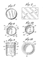
- Fig. 8 is a top plan view of the elevator cup of the dispenser of Fig. 1.
- Fig. 9 is a side elevation of the elevator cup of Fig. 8.
- Fig. 10 is a bottom plan view of the elevator cup of Figs. 8 and 9.
- Fig. 11 is a top plan view of the slotted, cup-carrying sleeve of the dispenser of Fig. 1.
- Fig. 12 is a side elevation of the inner sleeve of Fig. 11 and the base portion of the dispenser.
- Fig. 13 is a fragmentary vertical axial section, enlarged, of the elevator cup per se illustrating another embodiment of the invention.
- Fig. 14 is a top plan view of an elevator cup for a lipstick, illustrating another embodiment of the invention wherein the cup is adapted for use with a two-track shell and casing assemblage instead of a three track.
- Fig. 15 is a fragmentary elevational and sectional view showing a portion of a modified open-top loading channel of one of the tracks of the slotted shell.
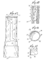
- Fig. 16 is a side elevational view of an improved elevator cup for lipsticks and the like, illustrating yet another embodiment of the invention.
- Fig. 17 is a top plan view of the shell of Fig. 16.
- Fig. 18 is an axial sectional view of the cup, taken on the line 18-18 of Fig. 17.
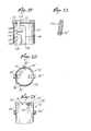
- Fig. 19 is a fragmentary side elevation of a modified form of elevator cup, showing a constrictive section of the slots in the inner sleeve, to ensure against removal of the cup once it has been filled with the lipstick substance.
- Fig. 20 is a top plan view of the elevator cup, showing a modified construction having two sets of resilient fingers with three fingers in each set.
- Fig. 21 is a fragmentary side elevational view of the cup of Fig. 20, and
- Fig. 22 is a fragmentary sectional view of a modified shape of resilient finger for the elevator cups of the invention.
- a novel and improved cosmetic applicator or dispenser 10 for a stick product such as a lipstick 12, comprising essentially three molded plastic components, an inner, substantially cylindrical sleeve having a slotted wall, an elevator cup that is slidable in the inner sleeve and which has radial projections extending through the slots in the sleeve, and a tubular manually-operable means in the form of an outer sleeve or spiral operating shell that is made to be open at both its opposite ends and is carried on the inner sleeve and turnable thereon.
- the inner sleeve (often referred to in the trade as a slotted shell) is designated 14, and has a generally cylindrical shape.
- the sleeve has a slotted, resilient side wall, with three longitudinally extending slots or tracks 16, 18 and 20 (Figs. 3, 2 and 4, respectively) that are, by the invention, disposed 120 degrees apart.
- the slot 18 has a pair of lateral or transverse passages 22, 24 at its ends, shown being of narrowed width with respect to the axial portion of the slot, the lateral passage 24 functioning to lock the elevator cup in a fully retracted position.
- the lateral passages of the slot 16 are designated 26 and 28, whereas those of the slot 20 are designated 30 and 32. As shown in Fig.
- the slot 18 terminates at an opening 22 disposed at its upper end. and in Figs. 3 and 4, the remaining two slots 16 and 20 respectively are open at their uppermost ends, at 34 and 36, respectively.
- the openings 22, 34, 36 enable portions of the cylindrical wall of the inner sleeve 14 adjacent the lip thereof to expand resiliently when the elevator cup is to be inserted into the sleeve during assembly, if this should be necessary.
- the novel product-containing elevator cup of the invention is designated 38, and comprises a generally cylindrical side wall 40 and a transverse intermediate wall 42, preferably provided with one or more vent openings 44, to permit air to bleed therethrough when the molded cosmetic product is inserted into the cup interior.
- Figures 3 and 4 show the elevator cup 38 almost fully inserted in the casing assemblage of the lipstick.
- the inner surface of the side wall 40' of the cup 38' optionally has a plurality of low ribs or splines 45', preferably four in number, to retain or anchor the lipstick product in position mostly against turning in the cup 38'.
- the cup 38 is provided with three circumferentially equispaced follower lugs or trunnions 46, 48 and 50, Fig. 8, each disposed 120 degrees from one another, the lugs being adapted to respectively extend completely through the slots 16, 20 and 18 in the inner sleeve 14.
- the height of the lugs 46-50 is such that they project beyond the outer surface of the sleeve 14.
- the outer open-ended sleeve or operating shell designated 52, Figs. 5-7, (often known in the trade as a spiral shell) is provided with three separate and distinct, spiral or helical grooves 54, 56 and 58 in its inner surface, the grooves having a width sufficient to accommodate the lugs 46-50 respectively, and the lugs being sufficiently long to extend fully into the grooves 54-58, respectively, as in Fig. 8.
- the cup 38 is halted at a point in its advancing travel, being locked in a slightly lower position against being fully advanced and ejected, by a novel restraining or locking means that is described below.
- cooperable slide bearing means are provided on the outer surface of the cup 38 and on the sleeve 14, to further minimize possible wobbling or canting of the cup.
- the slide bearing means comprises the interior wall surface of the sleeve 14, and a pair of spaced-apart circumferential ring surfaces 60, 62 on the exterior of the cup 38, adapted for engagement with the interior wall surface of the sleeve 14.
- supplemental bearing means are provided, in the form of three circumferentially spaced land surfaces or stabilizers 64, 66 and 68 on the exterior of the cup 38, these being engageable with the interior wall surface of the sleeve 14.
- the lands 64, 66 and 68 each straddle the wall 42 of the cup in an axial sense, extending from the one ring 62, which is axially above the wall 42, downwardly toward the lower end of the cup 38. It has been determined that with the provision of the rings 60, 62, and the three land surfaces 64, 66 and 68, as bearing surfaces, there results little or no tilting or canting of the cup 38 during normal operation of the cosmetic dispenser. This feature is considered especially important in conjunction with the improved pomade retention in the cup as described below, since the precisely-controlled cup carries the cosmetic pomade product or lipstick 12.
- the lipstick be axially aligned with the sleeve 14 and spaced uniformly from the side wall thereof, so as to not physically contact its inner surface.
- Such inadvertent contact might otherwise result in physical damage to the waxy stick material, as well as undesirable scraping of the waxy material by the inner surface, possibly creating wax fragments that could adhere to the stick, fall out of the casing and possibly soil skin, clothing, or other articles such as furniture, etc.
- the land surfaces 64, 66 and 68 are also equispaced from one another, i. e. spaced 120 degrees apart.
- Each land surface can be spaced generally midway between the immediately adjacent lugs, thus being displaced circumferentially 60 degrees from such lugs.
- the land surface 64 is disposed circumferentially between the lugs 46 and 48; the land surface 66 is disposed between the lugs 46 and 50; and the land surface 68 is disposed between the lugs 48 and 50.
- the rings 60, 62 are located such that the upper ring 60 is completely axially above the lugs 46, 48 and 50, whereas as noted above, the land surfaces 64, 66 and 68 extend a considerable distance from the location of the lower ring 62 toward the bottom of the cup 38, and thus have portions that extend axially below the location or plane of the lugs 46, 48 and 50, and also below the plane of the wall 42.
- this combination of lugs, land surfaces, and bearing rings provides an optimum drive/positioning structure for the cup 38, to assure smooth, jam-free operation of the dispenser, at the same time contributing to proper retention of the stick product in an axially aligned position such that it cannot scrape against the side walls of the sleeve or casing 14.
- the cup 38 further has a plurality of resilient castellations or resilient fingers 39 having rounded tips 39' and rounded inner surfaces 41' in its top rim, which have a special function, i. e. to securely anchor the lipstick in the cup without damaging its delicate physical make-up.
- a special function i. e. to securely anchor the lipstick in the cup without damaging its delicate physical make-up.
- the widespread method of anchoring the lipstick utilizes prominent tapered ribs that dig into the cosmetic mass. This fractures the lipstick and in some cases causes small pieces to break away from the body of the lipstick.
- silicone-based lipsticks and those containing a certain quantity of hydrocarbon solvents and even water result in a formulation that is not firmly held by the ribs, which bite into the product peripherally and vertically.
- the invention provides by means of the fingers 39, an effective clamping effect which holds the lipstick pomade tightly in the elevator cup 38 with a force that is at right angles to the forces which act to withdraw the lipstick from the cup.
- the vertical walls 40 of the cup 38 are molded no heavier or thicker than 0.38 millimeters, and are generally constructed from polyoxymethylene plastic.
- the fingers 39 have a scalloped or castellated configuration which forms a collet of sorts.
- the tips of the castellations are formed as softly curved contours, and normally are molded to flange outward in annular orientation like the petals of a flower, as seen in Fig. 13, thereby to permit easy insertion of the lipstick into the cup. This orientation exists prior to the elevator cup 38 being fully inserted at the maximum propel position.
- the castellations 39 protrude beyond the limits of the slotted and spiral shells as seen in Figs. 3 and 4.
- the cup 38 After the lipstick is initially inserted into the cup 38, the cup is placed fully into the slotted shell 14. This causes the castellations 39 to experience a depressing force, and flexes them inward so as to press them into the lipstick in the manner of a horizontal ring or collet, penetrating the pomade mass preferably to a depth of approximately 0.64 millimeters.
- the cup 38 can be provided with low or slightly protruding internal ribs 45' which will penetrate the pomade to a restricted depth that does not fracture the pomade, the protrusion being shown exaggerated in Fig. 13.
- Fig. 13 shows the fingers 13' as having the softly curved faces 41' that are engageable with the lipstick, to minimize damage thereto.
- the invention further provides a novel, simple restraining means to halt the advancing travel and lock the cup 38, or 38' against withdrawal from the shell 14 once it has been inserted with the lipstick contained therein.
- this means comprises a lateral locking stop shoulder or notch 21 comprising a lateral spur, so to speak, in the slot 20, and likewise additional locking notches 17 and 19 in the slots 16 and 18 respectively.
- the tracks 16, 18 and 20 are provided with these captivating transverse notches 17, 19 and 21 so that they will snag and entrap the follower pins 46, 48 and 50.
- the outer sleeve or operating shell 52 has an internal annular ledge 70 adjacent its lip, which fits beneath a circumferential bead 72, Fig. 12, on the outer surface of the shell 14, adjacent its lip.
- the bead is interrupted by the openings 22, 34 and 36 of the slots 16, 18 and 20 respectively.
- the outer sleeve 52 is thus retained by the engagement of the interrupted bead 72 with the annular ledge 70.
- the walls of the inner sleeve 14 adjacent its lip can collapse radially inwardly as permitted by the openings 24, 34 and 36 in the open slots 16, 18 and 20 respectively, to facilitate installation.
- FIG. 14 shows a top plan view of an elevator cup adapted for use with a two-track casing assemblage instead of a three-track assemblage.
- the cup 76 has castellations 78 similar to the castellations 39 of the first embodiment, but in place of the three follower pins 46, 48 and 50 of the first embodiment is has only two follower pins 80, which are located diametrically opposite each other.
- the inner shell 20 shown in dotted outline has only two oppositely-disposed tracks (not shown) that are similar to the tracks 16, 18 and 20 of the first embodiment, and the outer shell or casing 84 has only two spiral grooves (also not shown) that are similar to the grooves 54, 56 and 58 of the first embodiment.
- the two-track embodiment of Fig. 14 is generally similar to the three-track embodiment already described above in detail, and the operation is likewise similar.
- FIG. 15 Still another embodiment of the invention is illustrated in Fig. 15, wherein a modified offset loading channel is provided, that enables an easy initial assembly of the elevator cup into the casing assemblage.
- the elevator cup 90 having the castellations 92 in its upper rim is shown as being carried by the inner shell 94 which has a loading channel 96.
- the loading channel 96 is open at the top and has a laterally-offset open portion 98 at its top, that permits access to the channel by the follower pin of the cup.
- FIGs. 16, 17 and 18 Yet another embodiment of the invention is shown in Figs. 16, 17 and 18.
- the cup 98 shown in these figures is of the type having two trunnions 100 and having a plurality of castellations or fingers 102 of trapezoidal configuration, with narrowed supporting base portions 104.
- the uppermost, free portions of the fingers 106 are curvilinear as seen in Fig. 17.
- all edges of the fingers 102 are well rounded to minimize the likelihood of interference with the spiral grooves of the outer sleeve 52 and the slots of the inner sleeve 14.
- the cup 98 has the advantages explained above in connection with the previous constructions.
- FIG. 19 Another embodiment of the invention is illustrated in Fig. 19, wherein an inner sleeve 110 has been provided with a modified slot arrangement 112 which includes a vertical slot section 114, a back-check lateral or horizontal spur 116, an entry section 118 and a holding section or area 120.
- a modified slot arrangement 112 which includes a vertical slot section 114, a back-check lateral or horizontal spur 116, an entry section 118 and a holding section or area 120.
- the cup 76 then continues to move downward with the lugs 80 being guided along the wall 126 until the lugs sit in the holding area at the lower end of the slot 114.
- the consecutive movements of the lugs 80 are indicated by the dotted circles in Fig. 19.
- the lugs 80 move upward, hugging the wall 128 until the lugs 80 reach the holding or back-check spur 116.
- the point 130 ensures that the cup 76 does not pass upward beyond the spur 116.
- a modified cup 76' is illustrated, having two oppositely-disposed sets of fingers or castellations 39", three in each set, these being so arranged as to avoid interference with the slots of the inner sleeve 14, where such sleeve is constituted for use with cups having two elevator lugs instead of three.
- the castellations 39" have flat inner sides 132 instead of the rounded inner sides of the lugs 39' shown in Fig. 13.
- An elevator cup with the lugs 39" is easier to mold than a cup with the fingers 39'.
- the cup 76' has two smooth top edges 136 which are respectively disposed between and below the top edges of the two sets of fingers or castellations 39".
- the parts of the herein-described dispenser can be readily assembled, rendering the dispenser compatible with high speed automated equipment.
- Substantially no inelastic deformation of the sleeves 14, 52 or cup 38 occurs by virtue of the open slot configuration of the sleeve 14; limited expansion of the wall thereof adjacent its lip can thus readily occur during installation of the cup in the sleeve.
- the same open slot configuration similarly permits retraction, in a radially inward direction, of the same wall of the sleeve 14 adjacent its lip, upon the outer sleeve 52 being telescopically applied over the inner sleeve 14.
- the disclosed device is thus seen to represent a distinct advance and improvement in the field of cosmetic dispensers.
Landscapes
- Containers And Packaging Bodies Having A Special Means To Remove Contents (AREA)
- Cosmetics (AREA)
Abstract
Description
- Research and development of the present invention and application have not been Federally-sponsored, and no rights are given under any Federal program.
- This invention relates generally to cosmetic dispensers, and more particularly to dispensers of the type intended for use with lipsticks, eye shadow devices, and the like.
- The following references are hereby cited as being representative of some of the known prior art in the field to which the present invention pertains:
- U. S. Patents Nos.:
2,336,328 2,497,950 2,678,128 2,796,873 3,214,012 3,443,874 - British Patent No. 1,098,773 and British Published Application No. GB 2,143,212A.
- French Patents Nos. 946,797; 964,930; 77 32291; 1,052,053; and 2,406,972.
- Italian Patent No. 507,719.
- British Published Application No. GB 2,143,212A discloses a cosmetic stick holder construction utilizing a product-carrying cup having spacer portions (26) formed by slits in the upper edge of the cup in three places, the spacer portions each bearing radially outwardly on the inner sleeve of the dispenser in an elastic manner so as to purportedly minimize looseness of the cosmetic stick during its movement inside the sleeve.
- British Patent No. 1,098,773 relates to a cosmetic dispenser having a product-carrying cup that employs four circumferentially displaced spacers (14) to slidingly engage the inner surface of an inner casing, for guiding of the product-carrying cup therein.
- French Patent No. 77 32291 discloses a lipstick dispenser having a container, an outer sleeve, and a product cup. The product cup has two diametrically disposed camming lugs which are received in corresponding longitudinal slots in the container, and which respectively extend into two interior spiral or helical grooves in the outer sleeve.
- Other lipstick dispensers utilizing turnable outer sleeves having internal spiral grooves are shown in French Patent No. 1,052,053; French Patent No. 946,797; and French Patent No. 964,930. Nos. '053 and '930 have a single groove, whereas No. '797 shows two grooves that are diametrically opposed to one another.
- U. S. Patents Nos. 2,678,128; 3,214,012; 2,497,950; Italian Patent No. 507,719; and Canadian Patent No. 612,457 show various types of lipstick refill cartridges that have been proposed in the past, but which are considered to have realized little or no commercialization in the marketplace.
- Still other proposed arrangements include that of U. S. Patent No. 3,443,874, which discloses a cosmetic stick holder and method of manufacture thereof; and U. S. Patent No. 2,796,873, which sets forth a combined holder for lipstick, rouge, and eyeliner, the lipstick being advanceable in the casing in a linear direction by means of an external finger-engageable tab.
- Finally, U. S. Patent No. 2,336,328 illustrates a dispenser that employs a product-carrying cup which is advanceable and retractable by an internal screw that is engaged by a manually-operable thumbwheel axially mounted in the casing in such a manner that it is accessible from the side thereof.
- Although various attempts have been made to provide an economical dispenser which was characterized by smooth, essentially jam-free operation of the elevator cup and firm, nondestructive holding of the lipstick pomade, many of the devices currently known in the art have achieved little or no success in solving the problems.
- Noteworthy in the art of record is the lack of a cup drive mechanism that is truly balanced and symmetrical, and which prevents undesirable tilting or canting of the product-carrying cup and the lipstick carried therein.
- In some prior constructions utilizing two diametrically disposed cam lugs, a reasonable degree of balance was attained. However, it can be readily seen that driving a cup solely at two diametrically opposite points, as has been done in the prior art, still does not prevent tilting of the cup about the transverse axis that contains the points. As a consequence, leaning or "wobbling" of the cosmetic stick carried in the cup tends to occur. Under some circumstances, the stick actually scrapes against the inner surface of the dispenser casing, causing damage to the otherwise smooth exterior surface of the stick, and resulting in an undesirable build-up of scraped product on the casing interior. If fragments or scrapings subsequently re-adhere to the stick, they can be carried outside the casing and dropped when the stick is next advanced, possibly leading to soiled or stained clothing, furniture, etc.
- Various arrangements involving multiple, spring detent lugs on the outer surface of the product cup, as shown or suggested in some of the references noted above, have in some cases reduced the tendency for leaning or wobbling of the cup to occur. However, at present it is considered that there is still a need for improvement over known dispensers, from the standpoint of both economy and ease of operation.
- Thus the above disadvantages and drawbacks of prior cosmetic dispensers are largely obviated and the invention has for one object the provision of a novel and improved dispenser which is simple in its structure, reliable in operation, and which effectively, non-destructively holds the pomade in the cup and also maintains axial alignment between the product-carrying cup and the casing as the cup and pomade stick carried thereby are advanced and retracted.
- Still another object of the invention is to provide an improved cosmetic dispenser as above set forth, which virtually eliminates wobbling of the pcoduct-carrying cup and cosmetic stick, thereby reducing the possibility of scraping of the stick on the inner surface of the dispenser casing.
- Yet another object of the invention is to provide an improved cosmetic dispenser of the kind indicated, which is resistant to binding and possible malfunction as a consequence of inadvertent de-railing of positioning lugs of the cup from corresponding longitudinal tracks or grooves in the dispenser casing.
- Still another object of the invention is to provide an improved cosmetic dispenser as above characterized, which is economical to manufacture and assemble, thereby rendering the device commercially practical as to intended operativeness and economy in overall fabrication.
- In accomplishing the above objects the invention provides a cosmetic dispenser comprising, in combination an elevator cup having improved means to carry a solid cosmetic product and an improved locking of the cup against axial removal, a sleeve in which the cup is axially advanceable and retractable, said sleeve having longitudinal slots and the elevator cup having lugs respectively passing through and projecting from the slots of the sleeve, and an operating shell turnably mounted on the sleeve, having internal spiral tracks engaged by the lugs of the cup to propel the latter in response to relative turning between the shell and sleeve.
- The arrangement is such that the cup is advanced and retracted by balanced forces applied at uniformly spaced circumferential locations about the cup, and the pomade is precisely positioned in the cup against tilting or misalignment. The drive effects proper registration of the precisely-held cosmetic stick in the casing, and is effected by the respective engagement of the lugs at the circumferentially spaced locations with the walls of the spiral tracks. In addition, the combination comprises unique slide bearing surfaces, preferably at spaced locations between the lugs, to further stabilize the cup against inadvertent tilting, leaning or wobbling movements and the like.
- Other features and advantages will hereinafter appear.
- In the drawings, illustrating several embodiments of the invention:
- Fig. 1 is a top plan view of the improved cosmetic dispenser of the present invention with its cover removed, showing the slotted, cup-carrying or inner sleeve, the spiral operating shell or casing and the cosmetic stick product, such as a lipstick, carried within the inner shell.
- Fig. 2 is a side elevation of the dispenser, partly broken away, looking in the direction of the arrow "2" of Fig. 1.
- Fig. 3 is a side elevation, partly broken away, looking in the direction of the arrow "3" of Fig. 1. The elevator cup is disposed just short of being fully inserted into the casing assembly.
- Fig. 4 is a side elevation partly broken away and similar to the view of Fig. 3 but looking in the direction of the arrow "4" of Fig. 1.
- Fig. 5 is a top plan view of the assembly of the spiral operating shell or casing of the dispenser of Fig. 1, and the inner sleeve or slotted shell thereof.
- Fig. 6 is a view, partly in side elevation and partly in fragmentary section, of the assembly of the spiral operating shell of Fig. 5 and the inner sleeve or slotted shell.
- Fig. 7 is a development of the inner surface of the spiral operating shell of Figs. 5 and 6, illustrating three separate, spiral grooves therein, which receive corresponding projections or lugs on the elevator cup that carries the cosmetic stick product.
- Fig. 8 is a top plan view of the elevator cup of the dispenser of Fig. 1.
- Fig. 9 is a side elevation of the elevator cup of Fig. 8.
- Fig. 10 is a bottom plan view of the elevator cup of Figs. 8 and 9.
- Fig. 11 is a top plan view of the slotted, cup-carrying sleeve of the dispenser of Fig. 1.
- Fig. 12 is a side elevation of the inner sleeve of Fig. 11 and the base portion of the dispenser.
- Fig. 13 is a fragmentary vertical axial section, enlarged, of the elevator cup per se illustrating another embodiment of the invention.
- Fig. 14 is a top plan view of an elevator cup for a lipstick, illustrating another embodiment of the invention wherein the cup is adapted for use with a two-track shell and casing assemblage instead of a three track.
- Fig. 15 is a fragmentary elevational and sectional view showing a portion of a modified open-top loading channel of one of the tracks of the slotted shell.
- Fig. 16 is a side elevational view of an improved elevator cup for lipsticks and the like, illustrating yet another embodiment of the invention.
- Fig. 17 is a top plan view of the shell of Fig. 16.
- Fig. 18 is an axial sectional view of the cup, taken on the line 18-18 of Fig. 17.
- Fig. 19 is a fragmentary side elevation of a modified form of elevator cup, showing a constrictive section of the slots in the inner sleeve, to ensure against removal of the cup once it has been filled with the lipstick substance.
- Fig. 20 is a top plan view of the elevator cup, showing a modified construction having two sets of resilient fingers with three fingers in each set.
- Fig. 21 is a fragmentary side elevational view of the cup of Fig. 20, and
- Fig. 22 is a fragmentary sectional view of a modified shape of resilient finger for the elevator cups of the invention.
- Referring to Figs. 1 and 2 and in accordance with the present invention there is provided a novel and improved cosmetic applicator or
dispenser 10 for a stick product, such as alipstick 12, comprising essentially three molded plastic components, an inner, substantially cylindrical sleeve having a slotted wall, an elevator cup that is slidable in the inner sleeve and which has radial projections extending through the slots in the sleeve, and a tubular manually-operable means in the form of an outer sleeve or spiral operating shell that is made to be open at both its opposite ends and is carried on the inner sleeve and turnable thereon. - In Fig. 2, the inner sleeve (often referred to in the trade as a slotted shell) is designated 14, and has a generally cylindrical shape. The sleeve has a slotted, resilient side wall, with three longitudinally extending slots or
tracks 16, 18 and 20 (Figs. 3, 2 and 4, respectively) that are, by the invention, disposed 120 degrees apart. Theslot 18 has a pair of lateral ortransverse passages lateral passage 24 functioning to lock the elevator cup in a fully retracted position. The lateral passages of the slot 16 are designated 26 and 28, whereas those of theslot 20 are designated 30 and 32. As shown in Fig. 2, theslot 18 terminates at anopening 22 disposed at its upper end. and in Figs. 3 and 4, the remaining twoslots 16 and 20 respectively are open at their uppermost ends, at 34 and 36, respectively. Theopenings inner sleeve 14 adjacent the lip thereof to expand resiliently when the elevator cup is to be inserted into the sleeve during assembly, if this should be necessary. - We have discovered that by providing the
open slots inner sleeve 14 is needed during such assembly, thereby facilitating the overall procedure and eliminating the possibility of inadvertent cracking of theinner sleeve 14 as a consequence of excessive stretching of the plastic thereof, beyond its elastic limit. - Referring now to Figs. 8-10, the novel product-containing elevator cup of the invention is designated 38, and comprises a generally
cylindrical side wall 40 and a transverseintermediate wall 42, preferably provided with one ormore vent openings 44, to permit air to bleed therethrough when the molded cosmetic product is inserted into the cup interior. Figures 3 and 4 show theelevator cup 38 almost fully inserted in the casing assemblage of the lipstick. - In a modification of the invention shown in Fig. 13 the inner surface of the side wall 40' of the cup 38' optionally has a plurality of low ribs or splines 45', preferably four in number, to retain or anchor the lipstick product in position mostly against turning in the cup 38'.
- By the invention, the
cup 38 is provided with three circumferentially equispaced follower lugs ortrunnions slots inner sleeve 14. The height of the lugs 46-50 is such that they project beyond the outer surface of thesleeve 14. During insertion of thecup 38 into thesleeve 14, theopenings - Further by the invention, the outer open-ended sleeve or operating shell designated 52, Figs. 5-7, (often known in the trade as a spiral shell) is provided with three separate and distinct, spiral or
helical grooves shell 52 on thesleeve 14 can cause axial movement or travel of thecup 38 between a retracted position wherein thecup 38 is concealed in the sleeve 14 (not shown) and an advanced position wherein thecup 38 can approach the open end of the dispenser not quite as far as the initiation of insertion of the cup shown in Figs. 2-4. - As will be explained below, the
cup 38 is halted at a point in its advancing travel, being locked in a slightly lower position against being fully advanced and ejected, by a novel restraining or locking means that is described below. - We have found that by providing the three
grooves shell 52, a highly desirable balanced precise force is applied to thecup 38 at three equidistant circumferentially spaced points, thereby avoiding any tendency for thelugs grooves - Further by the invention, cooperable slide bearing means are provided on the outer surface of the
cup 38 and on thesleeve 14, to further minimize possible wobbling or canting of the cup. The slide bearing means comprises the interior wall surface of thesleeve 14, and a pair of spaced-apart circumferential ring surfaces 60, 62 on the exterior of thecup 38, adapted for engagement with the interior wall surface of thesleeve 14. - In addition, supplemental bearing means are provided, in the form of three circumferentially spaced land surfaces or
stabilizers cup 38, these being engageable with the interior wall surface of thesleeve 14. Thelands wall 42 of the cup in an axial sense, extending from the onering 62, which is axially above thewall 42, downwardly toward the lower end of thecup 38. It has been determined that with the provision of therings land surfaces cup 38 during normal operation of the cosmetic dispenser. This feature is considered especially important in conjunction with the improved pomade retention in the cup as described below, since the precisely-controlled cup carries the cosmetic pomade product orlipstick 12. - Considering the soft, waxy composition of lipsticks generally, it is important that the lipstick be axially aligned with the
sleeve 14 and spaced uniformly from the side wall thereof, so as to not physically contact its inner surface. Such inadvertent contact might otherwise result in physical damage to the waxy stick material, as well as undesirable scraping of the waxy material by the inner surface, possibly creating wax fragments that could adhere to the stick, fall out of the casing and possibly soil skin, clothing, or other articles such as furniture, etc. - Further, by the invention and in addition to the three
lugs land surface 64 is disposed circumferentially between thelugs land surface 66 is disposed between thelugs land surface 68 is disposed between thelugs - As shown in Fig. 9, the
rings upper ring 60 is completely axially above thelugs lower ring 62 toward the bottom of thecup 38, and thus have portions that extend axially below the location or plane of thelugs wall 42. It is considered that this combination of lugs, land surfaces, and bearing rings provides an optimum drive/positioning structure for thecup 38, to assure smooth, jam-free operation of the dispenser, at the same time contributing to proper retention of the stick product in an axially aligned position such that it cannot scrape against the side walls of the sleeve orcasing 14. - In accordance with the present invention, the
cup 38 further has a plurality of resilient castellations orresilient fingers 39 having rounded tips 39' and rounded inner surfaces 41' in its top rim, which have a special function, i. e. to securely anchor the lipstick in the cup without damaging its delicate physical make-up. Currently the widespread method of anchoring the lipstick utilizes prominent tapered ribs that dig into the cosmetic mass. This fractures the lipstick and in some cases causes small pieces to break away from the body of the lipstick. In more recent formulae, silicone-based lipsticks and those containing a certain quantity of hydrocarbon solvents and even water, result in a formulation that is not firmly held by the ribs, which bite into the product peripherally and vertically. - The invention, however, provides by means of the
fingers 39, an effective clamping effect which holds the lipstick pomade tightly in theelevator cup 38 with a force that is at right angles to the forces which act to withdraw the lipstick from the cup. Preferably thevertical walls 40 of thecup 38 are molded no heavier or thicker than 0.38 millimeters, and are generally constructed from polyoxymethylene plastic. Thefingers 39 have a scalloped or castellated configuration which forms a collet of sorts. The tips of the castellations are formed as softly curved contours, and normally are molded to flange outward in annular orientation like the petals of a flower, as seen in Fig. 13, thereby to permit easy insertion of the lipstick into the cup. This orientation exists prior to theelevator cup 38 being fully inserted at the maximum propel position. Thecastellations 39 protrude beyond the limits of the slotted and spiral shells as seen in Figs. 3 and 4. - After the lipstick is initially inserted into the
cup 38, the cup is placed fully into the slottedshell 14. This causes thecastellations 39 to experience a depressing force, and flexes them inward so as to press them into the lipstick in the manner of a horizontal ring or collet, penetrating the pomade mass preferably to a depth of approximately 0.64 millimeters. Optionally, as shown in the embodiment of Fig. 13, thecup 38 can be provided with low or slightly protruding internal ribs 45' which will penetrate the pomade to a restricted depth that does not fracture the pomade, the protrusion being shown exaggerated in Fig. 13. The embodiment of Fig. 13 employs both the castellations 39' and the ribs 45' to hold the lipstick, but the ribs 45' can be omitted since reliance can be placed entirely on thefingers 39 or 39', to securely anchor the pomade. With this latter arrangement the destructive effect of the ribs is eliminated and also the use of thefingers 39 or 39' provides for a far greater lead-in to facilitate lipstick insertion. Fig. 13 shows the fingers 13' as having the softly curved faces 41' that are engageable with the lipstick, to minimize damage thereto. - The invention further provides a novel, simple restraining means to halt the advancing travel and lock the
cup 38, or 38' against withdrawal from theshell 14 once it has been inserted with the lipstick contained therein. As seen in Fig. 12, this means comprises a lateral locking stop shoulder or notch 21 comprising a lateral spur, so to speak, in theslot 20, and likewise additional locking notches 17 and 19 in theslots 16 and 18 respectively. Thetracks transverse notches 17, 19 and 21 so that they will snag and entrap the follower pins 46, 48 and 50. In other words, when the elevator cup, after its first insertion in thesleeve 14, is shifted toward a protruding position, thetrunnions notches 17, 19 and 21 and these will prevent further ejecting movement of the cup. Thus thefingers 39 or 39' will be kept in their inward positions wherein they securely retain the lipstick in the cup. - Referring to Fig. 6, the outer sleeve or operating
shell 52 has an internalannular ledge 70 adjacent its lip, which fits beneath acircumferential bead 72, Fig. 12, on the outer surface of theshell 14, adjacent its lip. The bead is interrupted by theopenings slots outer sleeve 52 is thus retained by the engagement of the interruptedbead 72 with theannular ledge 70. During telescopic assembly of theouter sleeve 52 over theinner sleeve 14, the walls of theinner sleeve 14 adjacent its lip can collapse radially inwardly as permitted by theopenings open slots outer sleeve 52 becomes seated on anannular shoulder 74 at the lower end of the sleeve, Figs. 2-4 and 12, the resilience of the wall of thesleeve 14 restores its lip to its normal circular configuration, to thereby retain theouter sleeve 52. - In operation, after the insertion of the assembled
cup 38 andsleeve 14 in the manually-operable operating shell 52, the latter is turned on thesleeve 14 and the walls of thegrooves respective lugs cup 38 can thus be advanced or retracted, as thelugs respective grooves transverse restraining notches 17, 19 and 21 and are forced laterally so as to be seated therein. Locking in a retracted position occurs when the lugs arrive at thenotches - Another embodiment of the invention is illustrated in Fig. 14, which shows a top plan view of an elevator cup adapted for use with a two-track casing assemblage instead of a three-track assemblage. In this figure, the
cup 76 hascastellations 78 similar to thecastellations 39 of the first embodiment, but in place of the three follower pins 46, 48 and 50 of the first embodiment is has only two follower pins 80, which are located diametrically opposite each other. Theinner shell 20 shown in dotted outline has only two oppositely-disposed tracks (not shown) that are similar to thetracks casing 84 has only two spiral grooves (also not shown) that are similar to thegrooves - Still another embodiment of the invention is illustrated in Fig. 15, wherein a modified offset loading channel is provided, that enables an easy initial assembly of the elevator cup into the casing assemblage. In this figure the
elevator cup 90 having the castellations 92 in its upper rim is shown as being carried by theinner shell 94 which has aloading channel 96. By this invention, theloading channel 96 is open at the top and has a laterally-offsetopen portion 98 at its top, that permits access to the channel by the follower pin of the cup. - Yet another embodiment of the invention is shown in Figs. 16, 17 and 18. The
cup 98 shown in these figures is of the type having twotrunnions 100 and having a plurality of castellations orfingers 102 of trapezoidal configuration, with narrowed supportingbase portions 104. The uppermost, free portions of thefingers 106 are curvilinear as seen in Fig. 17. In this embodiment all edges of thefingers 102 are well rounded to minimize the likelihood of interference with the spiral grooves of theouter sleeve 52 and the slots of theinner sleeve 14. Thecup 98 has the advantages explained above in connection with the previous constructions. - Another embodiment of the invention is illustrated in Fig. 19, wherein an
inner sleeve 110 has been provided with a modifiedslot arrangement 112 which includes avertical slot section 114, a back-check lateral orhorizontal spur 116, anentry section 118 and a holding section orarea 120. With this arrangement after thecup 76 is filled with thelipstick 12, (Fig. 2) thelugs 80 move counterclockwise as viewed in Fig. 14 and in response to relative turning of theouter sleeve 52, passing between thepoints point 134 and theslot edge 126 which respectively are spaced apart for a close resistance-fit with the lugs to resist retrograde movement of the latter. Thecup 76 then continues to move downward with thelugs 80 being guided along thewall 126 until the lugs sit in the holding area at the lower end of theslot 114. The consecutive movements of thelugs 80 are indicated by the dotted circles in Fig. 19. For the reverse or upward movement of the cup and lugs, the latter move upward, hugging thewall 128 until thelugs 80 reach the holding or back-check spur 116. The point 130 ensures that thecup 76 does not pass upward beyond thespur 116. - In Figs. 20-22 a modified cup 76' is illustrated, having two oppositely-disposed sets of fingers or
castellations 39", three in each set, these being so arranged as to avoid interference with the slots of theinner sleeve 14, where such sleeve is constituted for use with cups having two elevator lugs instead of three. Thecastellations 39" have flatinner sides 132 instead of the rounded inner sides of the lugs 39' shown in Fig. 13. An elevator cup with thelugs 39" is easier to mold than a cup with the fingers 39'. As shown, the cup 76' has two smoothtop edges 136 which are respectively disposed between and below the top edges of the two sets of fingers orcastellations 39". - From the above it can be seen that we have provided a novel and improved cosmetic dispenser which is reliable in operation and use, and which substantially eliminates the tendency for the cosmetic stick product to crack or be damaged and scrape against the inner surface of the dispenser casing all by virtue of the novel combination of balanced drive forces applied to three spaced locations (lugs 46, 48 and 50) of the
elevator cup 38, and multiple bearing surfaces 60, 62, 64, 66 and 68 that are located on the exterior of thecup 38 and on thesleeve 14, the drive and bearing structures cooperating to largely eliminate potential problems with wobbling or tilting of thecup 38 and itscosmetic stick 12. - The parts of the herein-described dispenser can be readily assembled, rendering the dispenser compatible with high speed automated equipment. Substantially no inelastic deformation of the
sleeves cup 38 occurs by virtue of the open slot configuration of thesleeve 14; limited expansion of the wall thereof adjacent its lip can thus readily occur during installation of the cup in the sleeve. The same open slot configuration similarly permits retraction, in a radially inward direction, of the same wall of thesleeve 14 adjacent its lip, upon theouter sleeve 52 being telescopically applied over theinner sleeve 14. The disclosed device is thus seen to represent a distinct advance and improvement in the field of cosmetic dispensers. - Variations and modifications are possible without departing from the spirit of the invention.
- Each and every one of the appended claims defines an aspect of the invention which is separate and distinct from all others, and accordingly it is intended that each claim be treated in this manner when examined in the light of the prior art devices in any determination of novelty or validity.
Claims (17)
- A cosmetic dispenser comprising, in combination:a) an elevator cup having a top rim, said cup being adapted to receive and carry a solid cosmetic product,b) said cup having a plurality of resilient fingers extending along its top rim,c) an open-ended sleeve in which the cup can travel axially in advanceable and retractable directions,d) said fingers of the cup being adapted to engage cosmetic product in the cup, and to engage the inside of said sleeve to be forced inward thereby and into engagement with the cosmetic product therein,e) manually-operable means for causing said cup to travel in said sleeve toward the open end thereof, andf) restraining means for halting the advancing travel of the cup out of the sleeve, at a point in said travel wherein the said resilient fingers thereof still just experience the depressing force exerted on them by the sleeve.
- A cosmetic dispenser as set forth in claim 1, wherein:a) the open-ended sleeve has a longitudinal slot comprising a track,b) the cup has a follower lug which is received in the slot of the sleeve, andc) the restraining means comprises a stop shoulder on the sleeve, engageable with the follower lug on the cup to halt the travel of the latter.
- A cosmetic dispenser as set forth in claim 2, wherein the stop shoulder on the sleeve comprises a lateral spur slot connected with the longitudinal slot of the sleeve.
- A cosmetic dispenser as set forth in claim 2, wherein the longitudinal slot of the sleeve is open at the top of the sleeve to admit insertion of the cup in the sleeve top.
- A cosmetic dispenser as set forth in claim 4, wherein the opening of the longitudinal slot at the top thereof is offset laterally from the remainder of the slot.
- A cosmetic dispenser as set forth in claim 1, wherein the resilient fingers are rounded at their tips to avoid cutting into the cosmetic product.
- A cosmetic dispenser as set forth in claim 6, wherein the rounded tips of the said fingers have rounded inner surfaces which are engageable with the cosmetic product.
- A cosmetic dispenser as set forth in claim 3, wherein the sleeve has three tracks and the cup has three followers engaged respectively with the said three tracks.
- A cosmetic dispenser as set forth in claim 3, wherein the sleeve has two tracks and the cup has two followers engaged respectively with the said two tracks.
- A cosmetic dispenser as set forth in claim 8, wherein two of the three tracks are open at their tops.
- A cosmetic dispenser as set forth in claim 9, whereina) said two tracks are open at their tops, andb) the openings of said two tracks are offset laterally from the remainders of the slots.
- A cosmetic dispenser as set forth in claim 2, wherein the said cup is molded of plastic substance.
- A cosmetic dispenser as set forth in claim 1 wherein said fingers have a trapezoidal configuration.
- A cosmetic dispenser as set forth in claim 3 wherein the longitudinal slot of the open-ended sleeve has a constriction disposed above the said lateral spur slot, which is operable to minimize the likelihood of the elevator cup moving upward out of the open-ended sleeve.
- A cosmetic dispenser as set forth in claim 9, wherein the elevator cup has two sets of oppositely-disposed fingers, each set comprising a plurality of fingers and each set being disposed to avoid interference with the slots of the inner sleeve as the cup is being raised and lowered.
- A cosmetic dispenser as set forth in claim 15, wherein the elevator cup has two smooth top edges disposed respectively between and below the top edges of the said two sets of fingers.
- A cosmetic dispenser as set forth in claim 6, wherein the resilient fingers have flat inner sides to facilitate the molding of the cup.
Applications Claiming Priority (2)
| Application Number | Priority Date | Filing Date | Title |
|---|---|---|---|
| US09/173,266 US5988917A (en) | 1998-10-15 | 1998-10-15 | Cosmetic stick dispenser |
| US173266 | 1998-10-15 |
Publications (2)
| Publication Number | Publication Date |
|---|---|
| EP0995367A2 true EP0995367A2 (en) | 2000-04-26 |
| EP0995367A3 EP0995367A3 (en) | 2000-07-26 |
Family
ID=22631238
Family Applications (1)
| Application Number | Title | Priority Date | Filing Date |
|---|---|---|---|
| EP99203363A Withdrawn EP0995367A3 (en) | 1998-10-15 | 1999-10-13 | Cosmetic stick dispenser |
Country Status (5)
| Country | Link |
|---|---|
| US (1) | US5988917A (en) |
| EP (1) | EP0995367A3 (en) |
| JP (1) | JP2000135117A (en) |
| CN (1) | CN1252964A (en) |
| BR (1) | BR9904926A (en) |
Cited By (2)
| Publication number | Priority date | Publication date | Assignee | Title |
|---|---|---|---|---|
| US9820550B2 (en) | 2013-07-26 | 2017-11-21 | Axilone Plastique | System for holding a cosmetic product in the form of a stick of material, casing provided with such a holding system and assembly method |
| EP4520220A4 (en) * | 2022-12-09 | 2025-11-19 | Ppk Shanghai Packaging Co Ltd | Cosmetic container with replaceable lip and spare part |
Families Citing this family (22)
| Publication number | Priority date | Publication date | Assignee | Title |
|---|---|---|---|---|
| US6200049B1 (en) * | 2000-03-16 | 2001-03-13 | Plastic-Envases, C.A. | Cosmetic dispenser and method |
| FR2806273B1 (en) * | 2000-03-16 | 2002-10-04 | Oreal | DEVICE FOR PACKAGING AND APPLYING A COSMETIC OR CARE PRODUCT |
| ATE467364T1 (en) * | 2001-09-28 | 2010-05-15 | Kose Corp | CONTAINERS FOR STICK-TYPE COSMETICS |
| WO2004010820A1 (en) | 2002-07-29 | 2004-02-05 | Kose Corporation | Stick-like cosmetic paint container |
| US6834838B2 (en) * | 2003-04-10 | 2004-12-28 | General Motors Corporation | Selectively deployable cupholder |
| US7344056B2 (en) * | 2003-09-09 | 2008-03-18 | Toyota Motor Engineering & Manufacturing North America, Inc. | Collapsible container holder |
| US20060081739A1 (en) * | 2004-10-14 | 2006-04-20 | Jason Meissner | Self locking telescoping jack |
| US7381046B2 (en) * | 2006-06-27 | 2008-06-03 | Fu Chin Kuo | Lipstick making device |
| GB2446394A (en) * | 2007-02-09 | 2008-08-13 | Toly Products | Dispensing container for lipstick and the like |
| US8434959B2 (en) * | 2009-01-22 | 2013-05-07 | Kyle M. Bennett | Cosmetic container with mirrored element |
| US8851339B2 (en) * | 2009-02-19 | 2014-10-07 | S.C. Johnson & Son, Inc. | Applicator for self-adhesive products |
| FR2945921B1 (en) * | 2009-05-28 | 2014-07-25 | Rexam Beauty & Closures Inc | COSMETIC CONTAINER |
| JP5619917B2 (en) * | 2010-01-12 | 2014-11-05 | ロレアル | Mechanism for deploying a cosmetic stick, associated apparatus and method |
| US9474349B2 (en) | 2014-01-24 | 2016-10-25 | Hcp Packaging Usa, Inc. | Cosmetic dispenser with frictional resistance |
| US10525762B2 (en) | 2016-12-06 | 2020-01-07 | Sanford L.P. | Writing instrument side-knock mechanism |
| CN111836564B (en) * | 2017-11-08 | 2023-06-23 | 创新发明公司 | Cosmetic applicator and method of use thereof |
| US11382400B2 (en) | 2018-08-10 | 2022-07-12 | Go Products Co. | Material applicator |
| US11246394B2 (en) * | 2019-09-17 | 2022-02-15 | Zhuhai Ding Rong Plastic Products Co., Ltd | Environmentally friendly lipstick tube |
| US10881184B1 (en) * | 2019-10-01 | 2021-01-05 | Elc Management Llc | Container for a stick product |
| US11445799B2 (en) * | 2020-03-03 | 2022-09-20 | Zhuhai Ding Rong Plastic Products Co., Ltd | Cosmetic container with lipstick replacement device |
| EP4353364A4 (en) * | 2021-06-08 | 2025-04-02 | Eric Zembrod | PACKAGING/CARTRIDGE CASE |
| US12336616B1 (en) | 2024-12-20 | 2025-06-24 | Id Packaging Inc. | Container for a stick product |
Citations (13)
| Publication number | Priority date | Publication date | Assignee | Title |
|---|---|---|---|---|
| US2336328A (en) | 1942-01-16 | 1943-12-07 | Whalen Elizabeth | Lipstick |
| FR946797A (en) | 1947-05-14 | 1949-06-14 | Declic Soc | Automatic ejection tube for makeup sticks or other objects |
| US2497950A (en) | 1948-03-03 | 1950-02-21 | Marx & Co Louis | Changeable and refillable lipstick assembly |
| FR964930A (en) | 1950-08-29 | |||
| FR1052053A (en) | 1952-03-04 | 1954-01-21 | Coty Sa | Replacement device for lipstick and similar materials in case |
| US2678128A (en) | 1950-09-27 | 1954-05-11 | Sherman Claudine Reine | Refill cartridge for lipstick holders |
| US2796873A (en) | 1954-12-29 | 1957-06-25 | William G Little | Combination lipstick holder |
| CA612457A (en) | 1961-01-10 | M. Croce Santy | Method of filling lipstick containers | |
| US3214012A (en) | 1962-02-09 | 1965-10-26 | Mack William | Lipstick-refill dispenser |
| GB1098773A (en) | 1965-08-24 | 1968-01-10 | Aerosol Inv S And Dev S A Aids | Lipstick cartridge |
| US3443874A (en) | 1965-09-13 | 1969-05-13 | Oreal | Package containing stick material |
| FR2406972A1 (en) | 1977-10-26 | 1979-05-25 | Collet Claude | Lipstick tube assembly mfr. - has sleeve and inner tube moulded in one piece and joined by shear lugs |
| GB2143212A (en) | 1983-07-11 | 1985-02-06 | Oreal | A lipstick holder cup and sleeve of a lipstick unit and lipstick unit comprising it |
Family Cites Families (5)
| Publication number | Priority date | Publication date | Assignee | Title |
|---|---|---|---|---|
| US2529673A (en) * | 1946-11-16 | 1950-11-14 | Blake Lucille | Lipstick holder |
| US4991987A (en) * | 1990-01-23 | 1991-02-12 | Risdon Corporation | Cosmetic container |
| DE9100794U1 (en) * | 1991-01-24 | 1991-04-11 | Marbert GmbH, 4000 Düsseldorf | Lipstick tube |
| FR2696328B1 (en) * | 1991-11-29 | 1995-08-11 | Techpack Int | CASE FOR STICKS OF PASTY COSMETIC, PHARMACEUTICAL OR SIMILAR PRODUCTS. |
| US5186561A (en) * | 1992-03-17 | 1993-02-16 | Risdon Corporation | Incremental feel cosmetic dispenser |
-
1998
- 1998-10-15 US US09/173,266 patent/US5988917A/en not_active Expired - Lifetime
-
1999
- 1999-10-13 EP EP99203363A patent/EP0995367A3/en not_active Withdrawn
- 1999-10-14 CN CN99122419.1A patent/CN1252964A/en active Pending
- 1999-10-14 JP JP11292794A patent/JP2000135117A/en active Pending
- 1999-10-15 BR BR9904926-0A patent/BR9904926A/en not_active Application Discontinuation
Patent Citations (13)
| Publication number | Priority date | Publication date | Assignee | Title |
|---|---|---|---|---|
| CA612457A (en) | 1961-01-10 | M. Croce Santy | Method of filling lipstick containers | |
| FR964930A (en) | 1950-08-29 | |||
| US2336328A (en) | 1942-01-16 | 1943-12-07 | Whalen Elizabeth | Lipstick |
| FR946797A (en) | 1947-05-14 | 1949-06-14 | Declic Soc | Automatic ejection tube for makeup sticks or other objects |
| US2497950A (en) | 1948-03-03 | 1950-02-21 | Marx & Co Louis | Changeable and refillable lipstick assembly |
| US2678128A (en) | 1950-09-27 | 1954-05-11 | Sherman Claudine Reine | Refill cartridge for lipstick holders |
| FR1052053A (en) | 1952-03-04 | 1954-01-21 | Coty Sa | Replacement device for lipstick and similar materials in case |
| US2796873A (en) | 1954-12-29 | 1957-06-25 | William G Little | Combination lipstick holder |
| US3214012A (en) | 1962-02-09 | 1965-10-26 | Mack William | Lipstick-refill dispenser |
| GB1098773A (en) | 1965-08-24 | 1968-01-10 | Aerosol Inv S And Dev S A Aids | Lipstick cartridge |
| US3443874A (en) | 1965-09-13 | 1969-05-13 | Oreal | Package containing stick material |
| FR2406972A1 (en) | 1977-10-26 | 1979-05-25 | Collet Claude | Lipstick tube assembly mfr. - has sleeve and inner tube moulded in one piece and joined by shear lugs |
| GB2143212A (en) | 1983-07-11 | 1985-02-06 | Oreal | A lipstick holder cup and sleeve of a lipstick unit and lipstick unit comprising it |
Cited By (2)
| Publication number | Priority date | Publication date | Assignee | Title |
|---|---|---|---|---|
| US9820550B2 (en) | 2013-07-26 | 2017-11-21 | Axilone Plastique | System for holding a cosmetic product in the form of a stick of material, casing provided with such a holding system and assembly method |
| EP4520220A4 (en) * | 2022-12-09 | 2025-11-19 | Ppk Shanghai Packaging Co Ltd | Cosmetic container with replaceable lip and spare part |
Also Published As
| Publication number | Publication date |
|---|---|
| US5988917A (en) | 1999-11-23 |
| CN1252964A (en) | 2000-05-17 |
| BR9904926A (en) | 2001-03-20 |
| JP2000135117A (en) | 2000-05-16 |
| EP0995367A3 (en) | 2000-07-26 |
Similar Documents
| Publication | Publication Date | Title |
|---|---|---|
| US5988917A (en) | Cosmetic stick dispenser | |
| US6412999B1 (en) | Cosmetic container with push-back prevention feature | |
| US9113693B2 (en) | Mechanism for deploying a stick of cosmetic product, associated device and process | |
| JPH07213336A (en) | Application device for pasty products, especially cosmetic products such as lipstick | |
| US11129463B2 (en) | Refill lipstick cartridge | |
| EP0554974B1 (en) | Innerbody flex tab cosmetic dispenser | |
| CA2081634C (en) | Incremental feel cosmetic dispenser | |
| US5250030A (en) | Hypodermic syringe with a blockable piston capable of preventing its recharge and reuse | |
| US5636930A (en) | Cosmetic dispenser with cam locking feature | |
| EP0879569A1 (en) | An outer shell for a cosmetic container for preventing accidental removal of the shell's cover | |
| US5000601A (en) | Smooth drive cosmetic container | |
| JP2016527019A (en) | Device for holding a cosmetic product in the form of a bar of material, a container provided with such a holding device, and an assembly method | |
| AU693689B2 (en) | Expendable mass retention devices for expellant holders | |
| EP4216754B1 (en) | Refillable cosmetic dispenser | |
| EP1098577B1 (en) | Product dispenser and holder | |
| US3346103A (en) | Lipstick holder | |
| CA2331208C (en) | Mass retention device with bellows | |
| US5899620A (en) | Lipstick container with increased carrier ride-by force | |
| CN112135547A (en) | stick cosmetic container | |
| US2347774A (en) | Cosmetic holder | |
| US5727891A (en) | Ointment dispenser with kick-start mechanism | |
| US2393677A (en) | Cosmetic holder | |
| US10524557B1 (en) | Lock for cosmetic holder | |
| KR20230066142A (en) | Double Ended Stick Mechanism | |
| JP3522826B2 (en) | Lifting stick type cosmetic container |
Legal Events
| Date | Code | Title | Description |
|---|---|---|---|
| PUAI | Public reference made under article 153(3) epc to a published international application that has entered the european phase |
Free format text: ORIGINAL CODE: 0009012 |
|
| AK | Designated contracting states |
Kind code of ref document: A2 Designated state(s): DE ES FR GB IT |
|
| AX | Request for extension of the european patent |
Free format text: AL;LT;LV;MK;RO;SI |
|
| PUAL | Search report despatched |
Free format text: ORIGINAL CODE: 0009013 |
|
| AK | Designated contracting states |
Kind code of ref document: A3 Designated state(s): AT BE CH CY DE DK ES FI FR GB GR IE IT LI LU MC NL PT SE |
|
| AX | Request for extension of the european patent |
Free format text: AL;LT;LV;MK;RO;SI |
|
| 17P | Request for examination filed |
Effective date: 20010120 |
|
| AKX | Designation fees paid |
Free format text: DE ES FR GB IT |
|
| STAA | Information on the status of an ep patent application or granted ep patent |
Free format text: STATUS: THE APPLICATION IS DEEMED TO BE WITHDRAWN |
|
| 18D | Application deemed to be withdrawn |
Effective date: 20030501 |