EP0995389A2 - Einsatz für Badewannen - Google Patents
Einsatz für Badewannen Download PDFInfo
- Publication number
- EP0995389A2 EP0995389A2 EP99121116A EP99121116A EP0995389A2 EP 0995389 A2 EP0995389 A2 EP 0995389A2 EP 99121116 A EP99121116 A EP 99121116A EP 99121116 A EP99121116 A EP 99121116A EP 0995389 A2 EP0995389 A2 EP 0995389A2
- Authority
- EP
- European Patent Office
- Prior art keywords
- backrest
- rubber mat
- bead
- bathtub
- rigid backrest
- Prior art date
- Legal status (The legal status is an assumption and is not a legal conclusion. Google has not performed a legal analysis and makes no representation as to the accuracy of the status listed.)
- Granted
Links
Images
Classifications
-
- A—HUMAN NECESSITIES
- A47—FURNITURE; DOMESTIC ARTICLES OR APPLIANCES; COFFEE MILLS; SPICE MILLS; SUCTION CLEANERS IN GENERAL
- A47K—SANITARY EQUIPMENT; ACCESSORIES THEREFOR, e.g. TOILET ACCESSORIES
- A47K3/00—Baths; Showers; Appurtenances therefor
- A47K3/12—Separate seats or body supports
- A47K3/125—Body supports
Definitions
- the invention relates to an insert for bathtubs consisting of a Backrest and a seat part with suction cups.
- US Pat. No. 5,388,286 makes a collapsible child bath seat with vertical side walls and a vertical backrest discloses, a seat provided there by hinges is connected to the backrest.
- British patent application 2 053 673 discloses a bathing aid for small children, which is formed in one piece and on the tub edge can be attached.
- the bathing aid itself only has a lying part, which supports the back and head of the toddler to be bathed.
- U.S. Patent 3,583,001 is the length of the bathtub shortening component has become known, which is formed in one piece and which is in its upper area at the edge of the bathtub supports.
- a child's bath seat is known from US Pat. No. 3,072,923 which is characterized by a seat belt and which also serves to support the child's head.
- German utility model 1 928 155 shows one as a back support serving insert without bottom part for bath tubs, which the seat comfort at the head of the bathtub.
- German utility model 69 23 603 discloses a bathtub insert with a support strip. Back and floor pads. being in The area of the drain in the bathtub is a cutout in the floor area this insert is provided to drain bath water guarantee.
- U.S. Patent No. 5,535,458 serves to increase comfort for the bathers through a chair-like Device, the back of which is supported on the head of the bathtub and the seat part is supported by hinges on the bottom of the bathtub.
- the object of the invention is to achieve this based on the steep foot area of a bathtub of use feed.
- This object is achieved according to the characterizing feature of the claim 1 solved in that for sitting at the steep end of a tub rigid backrest with a separate flexible one Rubber mat with suction cups as a seat part is positively connected.
- this has so far been the case practically unusable foot part of a tub in surprisingly simple Way of use, the desired by the bather Inclination of the backrest due to the bather's own weight according to sitting on the rubber mat provided with suction cups clearly is locked.
- the rigid backrest can counteract the inside edge of the tub, if there is a tap or something else be ajar.
- the invention also a Easy to assemble and disassemble insert for bathtubs created.
- Claim 3 under protection that the bead firmly on the rubber mat is arranged. This configuration creates a secure connection supported between backrest and rubber mat.
- Claim 4 protected that the bead with the rubber mat connected by a wide foot that the bead head over the entire Width of the rubber mat designed as a circular cylindrical rod and that the groove in the rigid backrest across the width the inherently rigid backrest is adapted to the contour of the bead head.
- Claim 5 under protection that the inherently rigid backrest sturdy frame and a rusty backrest area to support the back of the bather. This makes seating and Bathing comfort further increased.
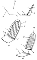
- Figure 1 shows a bathtub contour 10, which consists of a head end 11, a tub floor 5 and a foot part 13.
- the inherently rigid backrest 1 At the upper end of the foot part 13 is the inherently rigid backrest 1 and is based on a rubber mat 2, which is not shown Suction cups on the tub base 5 is pressed.
- the rigid backrest 1 can be any incline take to the foot part 13, so that it is ensured that when pulling of the drain plug bath water can escape from the drain undisturbed.
- the rigid backrest against the upper edge of the Foot part 13 can also be arranged on one in the foot part area Faucet to be ajar.
- the assembly of the bathtub insert according to Figure 2 is done by a connected to the rubber mat 2 via a wide foot 14 Bead 3 which laterally in an across the entire width of the intrinsically rigid backrest 1 extending groove 4 is inserted.
- the rubber mat 2 is form-fitting with its own stiffness Backrest 1 connected without the need for tools. This also allows a tool-free separation of the parts such. B. allow for cleaning.
- the invention makes it possible for a very large one Number of existing bathtubs has a comfortable, rigid backrest for the steep end of the bathtub.
- a rust-shaped backrest area 16 which by a stable frame 17 is surrounded (see FIG. 2 and FIG. 3) the seating comfort is significantly increased.
- the use of the bathtub also makes the foot part 13 of the bathtub comfortable designed so that not only one person their location can change during bathing, but it is made possible for the first time that additional occupancy of a bathtub can take place, what so far, especially when children use the bathtub was possible.
Landscapes
- Health & Medical Sciences (AREA)
- Public Health (AREA)
- Epidemiology (AREA)
- General Health & Medical Sciences (AREA)
- Bathtubs, Showers, And Their Attachments (AREA)
- Bathtub Accessories (AREA)
- Pharmaceuticals Containing Other Organic And Inorganic Compounds (AREA)
Abstract
Description
- Figur 1:
- Einen Badewanneneinsatz in eingesetztem Zustand
- Figur 2:
- Badewanneneinsatz Zusammenstellung
- Figur 3:
- Badewanneneinsatz explodiert
Claims (5)
- Einsatz für Badewannen bestehend aus einer Rückenlehne und einem Sitzteil mit Saugnäpfen, dadurch gekennzeichnet, daß zum Sitzen am steilen Wannenende 13 eine eigensteife Rückenlehne 1 mit einer von dieser getrennten flexiblen Gummimatte 2 mit Saugnäpfen als Sitzteil formschlüssig verbunden ist.
- Einsatz nach Anspruch 1 dadurch gekennzeichnet, daß die Gummimatte 2 und die eigensteife Rückenlehne 1 mittels einer Wulst 3 und einer an der eigensteifen Rückenlehne 1 angeordneten Nut 4 verbunden ist.
- Einsatz nach Anspruch 1 und/oder 2 dadurch gekennzeichnet, daß die Wulst 3 an der Gummimatte 2 fest angeordnet ist.
- Einsatz nach einem oder mehreren der vorhergehenden Ansprüche dadurch gekennzeichnet, daß die Wulst 3 mit der Gummimatte 2 über einen breiten Fuß 14 verbunden ist, daß der Wulstkopf über die gesamte Breite der Gummimatte 2 als kreiszylindrischer Stab 15 ausgebildet ist, und daß die Nut 4 in der eigensteifen Rückenlehne 1 über die Breite der eigensteifen Rückenlehne 1 der Kontur des Wulstkopfes angepaßt ist.
- Einsatz nach einem oder mehreren vorhergehenden Ansprüche dadurch gekennzeichnet, daß die eigensteife Rückenlehne 1 einen stabilen Rahmen 17 und einen rostförmigen Lehnenbereich 16 besitzt, um den Rücken des oder der Badenden zu unterstützen.
Applications Claiming Priority (2)
| Application Number | Priority Date | Filing Date | Title |
|---|---|---|---|
| DE19848923A DE19848923C2 (de) | 1998-10-23 | 1998-10-23 | Einsatz für Badewannen |
| DE19848923 | 1998-10-23 |
Publications (3)
| Publication Number | Publication Date |
|---|---|
| EP0995389A2 true EP0995389A2 (de) | 2000-04-26 |
| EP0995389A3 EP0995389A3 (de) | 2000-12-06 |
| EP0995389B1 EP0995389B1 (de) | 2004-01-07 |
Family
ID=7885415
Family Applications (1)
| Application Number | Title | Priority Date | Filing Date |
|---|---|---|---|
| EP99121116A Expired - Lifetime EP0995389B1 (de) | 1998-10-23 | 1999-10-22 | Einsatz für Badewannen |
Country Status (3)
| Country | Link |
|---|---|
| EP (1) | EP0995389B1 (de) |
| AT (1) | ATE257357T1 (de) |
| DE (2) | DE19848923C2 (de) |
Families Citing this family (2)
| Publication number | Priority date | Publication date | Assignee | Title |
|---|---|---|---|---|
| DE102005033534A1 (de) | 2005-07-14 | 2007-01-18 | Aquatec Gmbh | Badewannenlifter |
| DE202007007274U1 (de) * | 2007-05-22 | 2007-07-26 | Böckle, Harald | Rückenlehne für Wannenlift |
Citations (9)
| Publication number | Priority date | Publication date | Assignee | Title |
|---|---|---|---|---|
| US2582439A (en) | 1949-10-12 | 1952-01-15 | Luxury Gifts Inc | Pneumatic seat and back rest lounging device |
| US3072923A (en) | 1961-03-23 | 1963-01-15 | Zuke Amelia | Bath seat |
| DE1928155U (de) | 1965-10-08 | 1965-12-02 | Eugen Wolf Versandhaus Und Wae | Als rueckenstuetze dienender einsatz fuer badewannen. |
| DE6923603U (de) | 1969-06-05 | 1969-10-23 | Magdalene Parac-Ronge | Badewanneneinlage |
| US3583001A (en) | 1969-03-07 | 1971-06-08 | Harold R Steinhoff | Bath tub back rest |
| GB2053673A (en) | 1979-07-13 | 1981-02-11 | Mothercare Ltd | Improvements in or relating to baths for babies |
| US5388286A (en) | 1993-12-08 | 1995-02-14 | Davenport; Sharon G. | Infant bath seat device |
| US5535458A (en) | 1995-04-26 | 1996-07-16 | Siverly; Terry L. | Bathing seat |
| DE19627564A1 (de) | 1996-03-13 | 1997-09-18 | Behrend Meinen | Rückenlehne für Badewannen |
Family Cites Families (3)
| Publication number | Priority date | Publication date | Assignee | Title |
|---|---|---|---|---|
| US1759348A (en) * | 1929-11-13 | 1930-05-20 | Fishman Morris | Bathtub cushion and mat |
| CH240759A (de) * | 1944-12-01 | 1946-01-31 | Gaberthueel Albert | In Badewannen einzusetzende Rücklehne. |
| US4754503A (en) * | 1987-04-08 | 1988-07-05 | Martin Ida M | Shampoo support for children |
-
1998
- 1998-10-23 DE DE19848923A patent/DE19848923C2/de not_active Expired - Fee Related
-
1999
- 1999-10-22 DE DE59908236T patent/DE59908236D1/de not_active Expired - Fee Related
- 1999-10-22 AT AT99121116T patent/ATE257357T1/de not_active IP Right Cessation
- 1999-10-22 EP EP99121116A patent/EP0995389B1/de not_active Expired - Lifetime
Patent Citations (9)
| Publication number | Priority date | Publication date | Assignee | Title |
|---|---|---|---|---|
| US2582439A (en) | 1949-10-12 | 1952-01-15 | Luxury Gifts Inc | Pneumatic seat and back rest lounging device |
| US3072923A (en) | 1961-03-23 | 1963-01-15 | Zuke Amelia | Bath seat |
| DE1928155U (de) | 1965-10-08 | 1965-12-02 | Eugen Wolf Versandhaus Und Wae | Als rueckenstuetze dienender einsatz fuer badewannen. |
| US3583001A (en) | 1969-03-07 | 1971-06-08 | Harold R Steinhoff | Bath tub back rest |
| DE6923603U (de) | 1969-06-05 | 1969-10-23 | Magdalene Parac-Ronge | Badewanneneinlage |
| GB2053673A (en) | 1979-07-13 | 1981-02-11 | Mothercare Ltd | Improvements in or relating to baths for babies |
| US5388286A (en) | 1993-12-08 | 1995-02-14 | Davenport; Sharon G. | Infant bath seat device |
| US5535458A (en) | 1995-04-26 | 1996-07-16 | Siverly; Terry L. | Bathing seat |
| DE19627564A1 (de) | 1996-03-13 | 1997-09-18 | Behrend Meinen | Rückenlehne für Badewannen |
Also Published As
| Publication number | Publication date |
|---|---|
| DE19848923C2 (de) | 2000-07-13 |
| DE19848923A1 (de) | 1999-04-29 |
| DE59908236D1 (de) | 2004-02-12 |
| EP0995389A3 (de) | 2000-12-06 |
| ATE257357T1 (de) | 2004-01-15 |
| EP0995389B1 (de) | 2004-01-07 |
Similar Documents
| Publication | Publication Date | Title |
|---|---|---|
| DE69003942T2 (de) | Erhöhter und aufgelegter Klosettsitz und Sicherungsklammer. | |
| DE69835533T2 (de) | Haltestange bei toiletten | |
| DE2207738A1 (de) | Sitz für eine sanitäre Einrichtung, z.B. einen Nachtstuhl oder ein Wasserklosett | |
| DE19848923C2 (de) | Einsatz für Badewannen | |
| DE19706254C1 (de) | Toilette mit einem Sitzbereich und einer Schüssel | |
| DE3829470C1 (en) | A piece of seating furniture with neck support | |
| DE102013109283A1 (de) | Hochstuhl zum Waschen eines Kleinkindes | |
| DE3518127C2 (de) | Griffbefestigungssystem | |
| EP0460410B1 (de) | Badewanne mit Fussstützen | |
| DE3042037C2 (de) | Badewanne | |
| EP0212434B1 (de) | Orthopädisches Mehrzweckmöbel | |
| EP0729723B1 (de) | Badewanne mit erhöhtem Benutzungskomfort | |
| EP0860136A2 (de) | Duschwaschsitz | |
| DE19934571B4 (de) | Duschhocker und Aufsatz-Einrichtung für einen Duschhocker | |
| DE29721043U1 (de) | Duschwaschsitz | |
| DE8522893U1 (de) | Sitz-Liege-Möbel mit mehreren Polsterteilen, die wahlweise als Sitzmöbel oder als Liege verwendbar sind | |
| DE19963432C2 (de) | Badewanne mit Körperstütze im Bodenbereich | |
| DE20010343U1 (de) | Duschhocker | |
| DE29905447U1 (de) | Körperstütze für Sanitärobjekte | |
| DE20305904U1 (de) | Kabine zum Duschen und/oder Dampfbaden mit klappbaren Sitzen | |
| AT528387A4 (de) | Fußbadeeinheit und Wanne mit Fußbadeeinheit | |
| EP0490130A1 (de) | Hängender Badestuhl | |
| EP1579788A1 (de) | Mehrzweckmöbel | |
| DE29612218U1 (de) | Kindersitz | |
| DE29703161U1 (de) | Toilettenstuhl |
Legal Events
| Date | Code | Title | Description |
|---|---|---|---|
| PUAI | Public reference made under article 153(3) epc to a published international application that has entered the european phase |
Free format text: ORIGINAL CODE: 0009012 |
|
| AK | Designated contracting states |
Kind code of ref document: A2 Designated state(s): AT BE CH CY DE DK ES FI FR GB GR IE IT LI LU MC NL PT SE |
|
| AX | Request for extension of the european patent |
Free format text: AL;LT;LV;MK;RO;SI |
|
| PUAL | Search report despatched |
Free format text: ORIGINAL CODE: 0009013 |
|
| AK | Designated contracting states |
Kind code of ref document: A3 Designated state(s): AT BE CH CY DE DK ES FI FR GB GR IE IT LI LU MC NL PT SE |
|
| AX | Request for extension of the european patent |
Free format text: AL;LT;LV;MK;RO;SI |
|
| 17P | Request for examination filed |
Effective date: 20001130 |
|
| AKX | Designation fees paid |
Free format text: AT BE CH CY DE DK ES FI FR GB GR IE IT LI LU MC NL PT SE |
|
| RAP1 | Party data changed (applicant data changed or rights of an application transferred) |
Owner name: GIEHL, STEFAN |
|
| RIN1 | Information on inventor provided before grant (corrected) |
Inventor name: GIEHL, STEFAN |
|
| 17Q | First examination report despatched |
Effective date: 20020117 |
|
| RAP1 | Party data changed (applicant data changed or rights of an application transferred) |
Owner name: GIEHL, STEFAN |
|
| RIN1 | Information on inventor provided before grant (corrected) |
Inventor name: GIEHL, STEFAN |
|
| GRAH | Despatch of communication of intention to grant a patent |
Free format text: ORIGINAL CODE: EPIDOS IGRA |
|
| GRAS | Grant fee paid |
Free format text: ORIGINAL CODE: EPIDOSNIGR3 |
|
| GRAA | (expected) grant |
Free format text: ORIGINAL CODE: 0009210 |
|
| AK | Designated contracting states |
Kind code of ref document: B1 Designated state(s): AT BE CH CY DE DK ES FI FR GB GR IE IT LI LU MC NL PT SE |
|
| PG25 | Lapsed in a contracting state [announced via postgrant information from national office to epo] |
Ref country code: FI Free format text: LAPSE BECAUSE OF FAILURE TO SUBMIT A TRANSLATION OF THE DESCRIPTION OR TO PAY THE FEE WITHIN THE PRESCRIBED TIME-LIMIT Effective date: 20040107 Ref country code: ES Free format text: LAPSE BECAUSE OF FAILURE TO SUBMIT A TRANSLATION OF THE DESCRIPTION OR TO PAY THE FEE WITHIN THE PRESCRIBED TIME-LIMIT Effective date: 20040107 Ref country code: CY Free format text: LAPSE BECAUSE OF FAILURE TO SUBMIT A TRANSLATION OF THE DESCRIPTION OR TO PAY THE FEE WITHIN THE PRESCRIBED TIME-LIMIT Effective date: 20040107 |
|
| REG | Reference to a national code |
Ref country code: GB Ref legal event code: FG4D Free format text: NOT ENGLISH |
|
| REG | Reference to a national code |
Ref country code: CH Ref legal event code: EP |
|
| GBT | Gb: translation of ep patent filed (gb section 77(6)(a)/1977) |
Effective date: 20040107 |
|
| REG | Reference to a national code |
Ref country code: IE Ref legal event code: FG4D Free format text: GERMAN |
|
| REF | Corresponds to: |
Ref document number: 59908236 Country of ref document: DE Date of ref document: 20040212 Kind code of ref document: P |
|
| PG25 | Lapsed in a contracting state [announced via postgrant information from national office to epo] |
Ref country code: SE Free format text: LAPSE BECAUSE OF FAILURE TO SUBMIT A TRANSLATION OF THE DESCRIPTION OR TO PAY THE FEE WITHIN THE PRESCRIBED TIME-LIMIT Effective date: 20040407 Ref country code: GR Free format text: LAPSE BECAUSE OF FAILURE TO SUBMIT A TRANSLATION OF THE DESCRIPTION OR TO PAY THE FEE WITHIN THE PRESCRIBED TIME-LIMIT Effective date: 20040407 Ref country code: DK Free format text: LAPSE BECAUSE OF FAILURE TO SUBMIT A TRANSLATION OF THE DESCRIPTION OR TO PAY THE FEE WITHIN THE PRESCRIBED TIME-LIMIT Effective date: 20040407 |
|
| ET | Fr: translation filed | ||
| PLBE | No opposition filed within time limit |
Free format text: ORIGINAL CODE: 0009261 |
|
| STAA | Information on the status of an ep patent application or granted ep patent |
Free format text: STATUS: NO OPPOSITION FILED WITHIN TIME LIMIT |
|
| 26N | No opposition filed |
Effective date: 20041008 |
|
| PGFP | Annual fee paid to national office [announced via postgrant information from national office to epo] |
Ref country code: NL Payment date: 20061018 Year of fee payment: 8 Ref country code: GB Payment date: 20061018 Year of fee payment: 8 |
|
| PGFP | Annual fee paid to national office [announced via postgrant information from national office to epo] |
Ref country code: MC Payment date: 20061020 Year of fee payment: 8 Ref country code: IE Payment date: 20061020 Year of fee payment: 8 |
|
| PGFP | Annual fee paid to national office [announced via postgrant information from national office to epo] |
Ref country code: BE Payment date: 20061023 Year of fee payment: 8 Ref country code: AT Payment date: 20061023 Year of fee payment: 8 |
|
| PGFP | Annual fee paid to national office [announced via postgrant information from national office to epo] |
Ref country code: CH Payment date: 20061024 Year of fee payment: 8 |
|
| PGFP | Annual fee paid to national office [announced via postgrant information from national office to epo] |
Ref country code: IT Payment date: 20061031 Year of fee payment: 8 |
|
| PGFP | Annual fee paid to national office [announced via postgrant information from national office to epo] |
Ref country code: LU Payment date: 20061124 Year of fee payment: 8 |
|
| PG25 | Lapsed in a contracting state [announced via postgrant information from national office to epo] |
Ref country code: PT Free format text: LAPSE BECAUSE OF NON-PAYMENT OF DUE FEES Effective date: 20040607 |
|
| PGFP | Annual fee paid to national office [announced via postgrant information from national office to epo] |
Ref country code: DE Payment date: 20071019 Year of fee payment: 9 |
|
| BERE | Be: lapsed |
Owner name: GIEHL STEFAN Effective date: 20071031 |
|
| PGFP | Annual fee paid to national office [announced via postgrant information from national office to epo] |
Ref country code: FR Payment date: 20061023 Year of fee payment: 8 |
|
| PG25 | Lapsed in a contracting state [announced via postgrant information from national office to epo] |
Ref country code: MC Free format text: LAPSE BECAUSE OF NON-PAYMENT OF DUE FEES Effective date: 20071031 |
|
| GBPC | Gb: european patent ceased through non-payment of renewal fee |
Effective date: 20071022 |
|
| REG | Reference to a national code |
Ref country code: CH Ref legal event code: PL |
|
| NLV4 | Nl: lapsed or anulled due to non-payment of the annual fee |
Effective date: 20080501 |
|
| PG25 | Lapsed in a contracting state [announced via postgrant information from national office to epo] |
Ref country code: LI Free format text: LAPSE BECAUSE OF NON-PAYMENT OF DUE FEES Effective date: 20071031 Ref country code: CH Free format text: LAPSE BECAUSE OF NON-PAYMENT OF DUE FEES Effective date: 20071031 |
|
| PG25 | Lapsed in a contracting state [announced via postgrant information from national office to epo] |
Ref country code: AT Free format text: LAPSE BECAUSE OF NON-PAYMENT OF DUE FEES Effective date: 20071022 |
|
| PG25 | Lapsed in a contracting state [announced via postgrant information from national office to epo] |
Ref country code: BE Free format text: LAPSE BECAUSE OF NON-PAYMENT OF DUE FEES Effective date: 20071031 |
|
| REG | Reference to a national code |
Ref country code: FR Ref legal event code: ST Effective date: 20080630 |
|
| PG25 | Lapsed in a contracting state [announced via postgrant information from national office to epo] |
Ref country code: NL Free format text: LAPSE BECAUSE OF NON-PAYMENT OF DUE FEES Effective date: 20080501 Ref country code: IE Free format text: LAPSE BECAUSE OF NON-PAYMENT OF DUE FEES Effective date: 20071022 |
|
| PG25 | Lapsed in a contracting state [announced via postgrant information from national office to epo] |
Ref country code: GB Free format text: LAPSE BECAUSE OF NON-PAYMENT OF DUE FEES Effective date: 20071022 |
|
| PG25 | Lapsed in a contracting state [announced via postgrant information from national office to epo] |
Ref country code: FR Free format text: LAPSE BECAUSE OF NON-PAYMENT OF DUE FEES Effective date: 20071031 |
|
| PG25 | Lapsed in a contracting state [announced via postgrant information from national office to epo] |
Ref country code: LU Free format text: LAPSE BECAUSE OF NON-PAYMENT OF DUE FEES Effective date: 20071022 Ref country code: IT Free format text: LAPSE BECAUSE OF NON-PAYMENT OF DUE FEES Effective date: 20071022 Ref country code: DE Free format text: LAPSE BECAUSE OF NON-PAYMENT OF DUE FEES Effective date: 20090501 |