EP0995498A2 - Pumpspender und Herstellungsmethode - Google Patents
Pumpspender und Herstellungsmethode Download PDFInfo
- Publication number
- EP0995498A2 EP0995498A2 EP99120809A EP99120809A EP0995498A2 EP 0995498 A2 EP0995498 A2 EP 0995498A2 EP 99120809 A EP99120809 A EP 99120809A EP 99120809 A EP99120809 A EP 99120809A EP 0995498 A2 EP0995498 A2 EP 0995498A2
- Authority
- EP
- European Patent Office
- Prior art keywords
- housing
- pump
- side walls
- channels
- spaced
- Prior art date
- Legal status (The legal status is an assumption and is not a legal conclusion. Google has not performed a legal analysis and makes no representation as to the accuracy of the status listed.)
- Granted
Links
Images




Classifications
-
- B—PERFORMING OPERATIONS; TRANSPORTING
- B29—WORKING OF PLASTICS; WORKING OF SUBSTANCES IN A PLASTIC STATE IN GENERAL
- B29C—SHAPING OR JOINING OF PLASTICS; SHAPING OF MATERIAL IN A PLASTIC STATE, NOT OTHERWISE PROVIDED FOR; AFTER-TREATMENT OF THE SHAPED PRODUCTS, e.g. REPAIRING
- B29C45/00—Injection moulding, i.e. forcing the required volume of moulding material through a nozzle into a closed mould; Apparatus therefor
- B29C45/17—Component parts, details or accessories; Auxiliary operations
- B29C45/26—Moulds
-
- B—PERFORMING OPERATIONS; TRANSPORTING
- B05—SPRAYING OR ATOMISING IN GENERAL; APPLYING FLUENT MATERIALS TO SURFACES, IN GENERAL
- B05B—SPRAYING APPARATUS; ATOMISING APPARATUS; NOZZLES
- B05B11/00—Single-unit hand-held apparatus in which flow of contents is produced by the muscular force of the operator at the moment of use
- B05B11/01—Single-unit hand-held apparatus in which flow of contents is produced by the muscular force of the operator at the moment of use characterised by the means producing the flow
- B05B11/10—Pump arrangements for transferring the contents from the container to a pump chamber by a sucking effect and forcing the contents out through the dispensing nozzle
- B05B11/1001—Piston pumps
- B05B11/1009—Piston pumps actuated by a lever
- B05B11/1011—Piston pumps actuated by a lever without substantial movement of the nozzle in the direction of the pressure stroke
-
- B—PERFORMING OPERATIONS; TRANSPORTING
- B05—SPRAYING OR ATOMISING IN GENERAL; APPLYING FLUENT MATERIALS TO SURFACES, IN GENERAL
- B05B—SPRAYING APPARATUS; ATOMISING APPARATUS; NOZZLES
- B05B11/00—Single-unit hand-held apparatus in which flow of contents is produced by the muscular force of the operator at the moment of use
- B05B11/01—Single-unit hand-held apparatus in which flow of contents is produced by the muscular force of the operator at the moment of use characterised by the means producing the flow
- B05B11/10—Pump arrangements for transferring the contents from the container to a pump chamber by a sucking effect and forcing the contents out through the dispensing nozzle
- B05B11/1095—Pump arrangements for transferring the contents from the container to a pump chamber by a sucking effect and forcing the contents out through the dispensing nozzle with movable suction side
Definitions
- This invention relates to a pump dispenser and method of making it. More specifically, the invention relates to a one-piece pump body and housing of such a dispenser and a process for molding it in a simple two-part mold.
- the present invention undertakes to make a one-piece dispenser of the general type as that disclosed in McKinney patent 4,161,288 issued July 17, 1979.
- That dispenser ubiquitous and well thought of in the industry, features a two-piece housing comprising a housing top and a housing bottom enclosing a pumping chamber/tubular support and delivery tube.
- the trigger is pivoted to the housing bottom in a slot by pins disposed on opposite side walls if the slot.
- the present invention is a one-piece product and a process wherein the trigger pins, delivery tube, pumping chamber, tubular support and external housing are all molded in a simple two-part mold.
- the invention relates to a one-piece molded body and housing for a pump dispenser, the housing comprising a pair of spaced side walls and a top wall.
- a vertical tubular support and pumping cylinder are both spaced from the side walls and meet the top wall.
- a plurality of transverse webs extending between the side wall strengthen the structure, a delivery tube extending forward from an upper portion of the pumping cylinder and spaced down from the top wall.
- Box-like channels are formed on the inside of the side walls and support coaxial trigger pins, spacing them in from the side walls.
- the pump body and housing is formed in a simple two-piece mold which includes blades which extend down through the top wall of the housing to form the upper wall of the delivery tube. Additional blades extend down to form the channels and the trigger pins in cooperation with mold surfaces from the lower half of the mold.
- the interior of the tubular support and pump cylinder are formed by a cylindrical surface on the lower mold half.
- the lower half also forms the exterior of the tubular support and cylinder spaced from the inside surface of the side walls.
- a retractable core pin extends in laterally to meet the cylindrical surface and form the interior of the delivery tube.
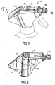
- a pump dispenser including a pump body and housing embodying the invention and made in accordance with the mold and process of the invention is generally designated 10 in Figs. 1 and 9.
- the one-piece housing and pump body is designated 12.
- the housing comprises (Fig. 9) side walls 14, a rear wall 16 and a top wall 18.
- a coaxial and unitary tubular support 20 and pump cylinder 21 (Fig. 8) is joined to the top and rear walls and is disposed intermediate and spaced from the side walls (Figs. 4, 8).
- a product delivery tube 22 extends forwardly from the pump cylinder.
- a pair of channels 24 comprising bridging walls 26 and side walls 28, the more forward of which extends inward from the bridging wall 26 of the channel for the purpose of retaining the trigger.
- the channels extend vertically along the side walls 14 to the top wall 18 and there terminate in slots 25 (Fig. 1). Disposed at the lower end of the respective channels 24 are the inwardly facing opposed aligned trigger pins 30.
- Transverse vertical stiffening webs 32 extend downward from the rear wall 16 (Fig. 9) and run between the two side walls 14.
- Spaced interior walls 34 run longitudinally vertically of the housing and extend down to the delivery pipe 22 defining a centerline slot 36.
- Transverse ribs 38 stiffen the interior walls 34.
- the pump cylinder is provided with a piston 40 having a built-in inlet ball check 42 and a downward tubular stem 44 which telescopingly engages a dip tube 46.
- a spring 48 inside the pump cylinder biases the piston downward.
- the lower end of the tubular support 20 engages the retainer 50 and the retainer has a central opening which slidably receives the piston stem 44.
- the retainer has a flange 52 on its lower end which lies inside the screw cap 54 and is adapted to be clamped against the finish of a container in the conventional way (see McKinney patent 4,161,288).
- the forward end of the delivery tube 22 is formed with a nozzle hub 60 onto which a nozzle cap 62 snaps and is rotatably held in a well known manner.
- An outlet check valve 64 of the type disclosed in the Smolen, Jr. patent 5,687,877 is used in the preferred embodiment.
- a pivoted trigger 66 has side openings (not shown) which snap onto the opposed pins 30 for pivotally mounting it.
- the yoke 68 at the rearward end of the trigger engages the lower end of the piston 40 to raise it when the trigger is squeezed.
- the wall 28 overlies the top of the trigger to aid in assembly.
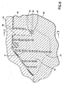
- Figs. 5 through 8 show the pump dispenser body and housing of the invention in the process of manufacture, that is, while still in its mold.
- the mold comprises the lower half 80 and the upper half 82. Additionally, there is the lateral core pin 84 (Fig. 5) which forms the interior of the delivery tube 22.
- the mold parts are shaped to produce the unitary body and housing above-described.
- the molding or coring out of the upper portion of the delivery tube 22 is achieved by the blade 86 (Fig. 5), a downward part of the upper mold half 82.
- the inner walls 26 of the channels are formed by the flanking blades 88 (Fig. 7).
- Blades 88 are also integral with the upper mold half 82.
- the lower portions of the flanking blades 88 are formed respectively with concave shapes 90 (Fig. 6) which serve to shape the upper halves of the trigger pins.
- the inside of the channels as described are formed by the outer blades 90 (Fig. 7) which extend upward as part of the lower mold half 80 spaced respectively from cavities 92 in the upper mold half. Inward from the lower ends of the outer blades 90 the lower half 80 is formed with a concave recess 94 which shapes the lower halves of the trigger pins 30 as described. To provide for a retaining wall 28 on the forward wall of the channel 24 there is a cavity 96 (Fig. 6) in the lower mold half 80.
- the lower mold half 80 (Fig. 8) is formed with a cylindrical opening 93 to form the outside of the tubular support 20 and pump cylinder 21. It includes a neck portion 94 which spaces the tubular support and pump cylinder 20, 21 from the side walls 14. This has been found necessary to assure that there are no sink marks on the inside of the pump cylinder to impair the pumping ability.
- a cylindrical shape 96 is formed concentrically within and spaced from the cylindrical opening 93. It forms the inside diameter of the pumping chamber/ tubular support.
- the slots 36 and 25 (fig. 1) left by the blades may remain uncovered and become part of the appearance of the dispenser or, if desired or necessary, they may be covered by an adhesively applied film or strip.
- dispenser pump body and housing, the mold, and the process have been shown in only one embodiment, it is not so limited but is of a scope defined by the following claim language which may be broadened by an extension of the right to exclude others from making, using or selling the invention as is appropriate under the doctrine of equivalents.
Landscapes
- Engineering & Computer Science (AREA)
- Manufacturing & Machinery (AREA)
- Mechanical Engineering (AREA)
- Containers And Packaging Bodies Having A Special Means To Remove Contents (AREA)
- Closures For Containers (AREA)
- Moulds For Moulding Plastics Or The Like (AREA)
- Reciprocating Pumps (AREA)
- Rotary Pumps (AREA)
- Structures Of Non-Positive Displacement Pumps (AREA)
Applications Claiming Priority (2)
| Application Number | Priority Date | Filing Date | Title |
|---|---|---|---|
| US09/176,752 US6032834A (en) | 1998-10-22 | 1998-10-22 | Pump dispenser and method of making it |
| US176752 | 1998-10-22 |
Publications (3)
| Publication Number | Publication Date |
|---|---|
| EP0995498A2 true EP0995498A2 (de) | 2000-04-26 |
| EP0995498A3 EP0995498A3 (de) | 2002-10-09 |
| EP0995498B1 EP0995498B1 (de) | 2004-01-14 |
Family
ID=22645683
Family Applications (1)
| Application Number | Title | Priority Date | Filing Date |
|---|---|---|---|
| EP99120809A Expired - Lifetime EP0995498B1 (de) | 1998-10-22 | 1999-10-21 | Pumpspender und Herstellungsmethode |
Country Status (9)
| Country | Link |
|---|---|
| US (1) | US6032834A (de) |
| EP (1) | EP0995498B1 (de) |
| JP (1) | JP2000142765A (de) |
| CN (1) | CN1113706C (de) |
| AU (1) | AU748346B2 (de) |
| BR (1) | BR9905103A (de) |
| CA (1) | CA2286406C (de) |
| CO (1) | CO5060427A1 (de) |
| DE (1) | DE69914154T2 (de) |
Families Citing this family (11)
| Publication number | Priority date | Publication date | Assignee | Title |
|---|---|---|---|---|
| US6286727B1 (en) * | 2000-05-04 | 2001-09-11 | Owens-Illinois Closure Inc. | Pump dispenser having ergonomic overhang and method of making it |
| US6726871B2 (en) * | 2001-06-07 | 2004-04-27 | Siemens Vdo Automotive, Inc. | Method and apparatus for attachment of air cleaner housing |
| DE10229618A1 (de) * | 2002-06-25 | 2004-01-29 | Ing. Erich Pfeiffer Gmbh | Dosierpumpe, Verfahren zu ihrer Herstellung und Vorrichtung zur Durchführung des Verfahrens |
| FR2853567B1 (fr) * | 2003-04-09 | 2006-06-23 | Rexam Dispensing Sys | Pulverisateur comprenant une pompe formant bouchon |
| NL1027982C2 (nl) * | 2005-01-10 | 2006-07-11 | Afa Polytek Bv | Dunwandige doseerinrichting met integraal vervaardigde trekker en veer, alsmede werkwijze voor het samenstellen daarvan. |
| US7455198B2 (en) * | 2006-03-07 | 2008-11-25 | Meadwestvaco Calmar, Inc. | Trigger forward pivot limit for a trigger sprayer |
| JP4834803B2 (ja) * | 2006-09-14 | 2011-12-14 | ランズバーグ・インダストリー株式会社 | 噴霧装置の製造方法 |
| JP4785152B2 (ja) * | 2008-12-09 | 2011-10-05 | キャニヨン株式会社 | トリガー式ポンプディスペンサー |
| US11247221B2 (en) * | 2016-09-12 | 2022-02-15 | Rieke Llc | Trigger sprayer |
| USD980069S1 (en) | 2020-07-14 | 2023-03-07 | Ball Corporation | Metallic dispensing lid |
| US12168551B2 (en) | 2021-03-01 | 2024-12-17 | Ball Corporation | Metal container and end closure with seal |
Citations (3)
| Publication number | Priority date | Publication date | Assignee | Title |
|---|---|---|---|---|
| US4161288A (en) | 1976-10-05 | 1979-07-17 | Creative Dispensing Systems, Inc. | Fluid dispenser method and apparatus |
| US5590834A (en) | 1994-07-22 | 1997-01-07 | Contico International, Inc. | One-piece trigger sprayer housing |
| US5687877A (en) | 1995-11-03 | 1997-11-18 | Owens-Illinois Closure Inc. | Pump dispenser having moveable outlet check valve element |
Family Cites Families (6)
| Publication number | Priority date | Publication date | Assignee | Title |
|---|---|---|---|---|
| DE3001688C2 (de) * | 1980-01-18 | 1981-12-17 | Kläger, Karlheinz, 8901 Neusäß | Handbetätigter Flüssigkeitszerstäuber |
| US4560095A (en) * | 1983-03-07 | 1985-12-24 | Stewart-Warner Corporation | Lever operated lubricator |
| ES273524Y (es) * | 1983-07-14 | 1985-04-16 | Monturas Y Fornituras S.A. | Pistola proyectora de liquidos |
| DE4342304A1 (de) * | 1993-12-11 | 1995-06-14 | Owens Illinois Closure Inc | Sprühpumpe |
| JP3042357B2 (ja) * | 1995-03-15 | 2000-05-15 | 東洋製罐株式会社 | トリガ式ポンプディスペンサ |
| US5755361A (en) * | 1996-01-11 | 1998-05-26 | The Fountainhead Group, Inc. | Pump sprayer |
-
1998
- 1998-10-22 US US09/176,752 patent/US6032834A/en not_active Expired - Lifetime
-
1999
- 1999-10-14 CA CA002286406A patent/CA2286406C/en not_active Expired - Fee Related
- 1999-10-20 AU AU55963/99A patent/AU748346B2/en not_active Ceased
- 1999-10-21 CO CO99066743A patent/CO5060427A1/es unknown
- 1999-10-21 BR BR9905103-6A patent/BR9905103A/pt active Search and Examination
- 1999-10-21 DE DE69914154T patent/DE69914154T2/de not_active Expired - Fee Related
- 1999-10-21 EP EP99120809A patent/EP0995498B1/de not_active Expired - Lifetime
- 1999-10-22 CN CN99126091A patent/CN1113706C/zh not_active Expired - Fee Related
- 1999-10-22 JP JP11300659A patent/JP2000142765A/ja not_active Ceased
Patent Citations (4)
| Publication number | Priority date | Publication date | Assignee | Title |
|---|---|---|---|---|
| US4161288A (en) | 1976-10-05 | 1979-07-17 | Creative Dispensing Systems, Inc. | Fluid dispenser method and apparatus |
| US5590834A (en) | 1994-07-22 | 1997-01-07 | Contico International, Inc. | One-piece trigger sprayer housing |
| US5656227A (en) | 1994-07-22 | 1997-08-12 | Contico International, Inc. | Method of making a one-piece trigger sprayer housing |
| US5687877A (en) | 1995-11-03 | 1997-11-18 | Owens-Illinois Closure Inc. | Pump dispenser having moveable outlet check valve element |
Also Published As
| Publication number | Publication date |
|---|---|
| JP2000142765A (ja) | 2000-05-23 |
| CN1113706C (zh) | 2003-07-09 |
| CO5060427A1 (es) | 2001-07-30 |
| EP0995498B1 (de) | 2004-01-14 |
| CA2286406A1 (en) | 2000-04-22 |
| CN1253041A (zh) | 2000-05-17 |
| DE69914154T2 (de) | 2004-08-26 |
| AU748346B2 (en) | 2002-06-06 |
| BR9905103A (pt) | 2000-08-29 |
| AU5596399A (en) | 2000-05-04 |
| CA2286406C (en) | 2005-03-01 |
| US6032834A (en) | 2000-03-07 |
| EP0995498A3 (de) | 2002-10-09 |
| DE69914154D1 (de) | 2004-02-19 |
Similar Documents
| Publication | Publication Date | Title |
|---|---|---|
| EP0995498B1 (de) | Pumpspender und Herstellungsmethode | |
| US6286728B1 (en) | Shroud cover for trigger sprayer | |
| US5337928A (en) | Sealing gasket for a trigger sprayer | |
| US7281674B2 (en) | Sprayer push-button | |
| RU2248926C2 (ru) | Устройство для расфасовки и выдачи продукта, в частности, в виде образца | |
| US6415959B1 (en) | Low capacity pump with enhanced compatibility | |
| US4955511A (en) | Trigger actuated pump and method of making same | |
| US5656227A (en) | Method of making a one-piece trigger sprayer housing | |
| AU8942198A (en) | Upright/inverted sprayer | |
| US5687877A (en) | Pump dispenser having moveable outlet check valve element | |
| US6343916B1 (en) | Pump body and method for making same | |
| US7520409B2 (en) | Distributor for a liquid or gel product | |
| JP2962704B2 (ja) | 複数キャビティ付ディスペンサパッケージ | |
| MXPA99009635A (en) | Pump supplier and my manufacturing method | |
| US6026989A (en) | Multichamber squeeze tube integrally molded in one piece and container assembly incorporating same | |
| US5553757A (en) | Cream dispenser head | |
| US7694895B2 (en) | Push-button sprayer equipped with a projecting side nozzle | |
| JP3859873B2 (ja) | 液体噴出容器 | |
| EP1029807A1 (de) | Zerstäuberkappe für Sprühdose | |
| CA2214600C (en) | Pump trigger assembly for a trigger sprayer | |
| KR200331087Y1 (ko) | 분해 조립구조를 갖는 펌프 디스펜서 | |
| HK1084625A (en) | Push-button sprayer equipped with a projecting side nozzle |
Legal Events
| Date | Code | Title | Description |
|---|---|---|---|
| PUAI | Public reference made under article 153(3) epc to a published international application that has entered the european phase |
Free format text: ORIGINAL CODE: 0009012 |
|
| AK | Designated contracting states |
Kind code of ref document: A2 Designated state(s): AT BE CH CY DE DK ES FI FR GB GR IE IT LI LU MC NL PT SE |
|
| AX | Request for extension of the european patent |
Free format text: AL;LT;LV;MK;RO;SI |
|
| PUAL | Search report despatched |
Free format text: ORIGINAL CODE: 0009013 |
|
| AK | Designated contracting states |
Kind code of ref document: A3 Designated state(s): AT BE CH CY DE DK ES FI FR GB GR IE IT LI LU MC NL PT SE |
|
| AX | Request for extension of the european patent |
Free format text: AL;LT;LV;MK;RO;SI |
|
| 17P | Request for examination filed |
Effective date: 20030121 |
|
| AKX | Designation fees paid |
Designated state(s): DE FR GB IT |
|
| GRAP | Despatch of communication of intention to grant a patent |
Free format text: ORIGINAL CODE: EPIDOSNIGR1 |
|
| GRAS | Grant fee paid |
Free format text: ORIGINAL CODE: EPIDOSNIGR3 |
|
| GRAA | (expected) grant |
Free format text: ORIGINAL CODE: 0009210 |
|
| AK | Designated contracting states |
Kind code of ref document: B1 Designated state(s): DE FR GB IT |
|
| REG | Reference to a national code |
Ref country code: GB Ref legal event code: FG4D |
|
| REG | Reference to a national code |
Ref country code: IE Ref legal event code: FG4D |
|
| REF | Corresponds to: |
Ref document number: 69914154 Country of ref document: DE Date of ref document: 20040219 Kind code of ref document: P |
|
| ET | Fr: translation filed | ||
| PG25 | Lapsed in a contracting state [announced via postgrant information from national office to epo] |
Ref country code: GB Free format text: LAPSE BECAUSE OF NON-PAYMENT OF DUE FEES Effective date: 20041021 |
|
| PLBE | No opposition filed within time limit |
Free format text: ORIGINAL CODE: 0009261 |
|
| STAA | Information on the status of an ep patent application or granted ep patent |
Free format text: STATUS: NO OPPOSITION FILED WITHIN TIME LIMIT |
|
| 26N | No opposition filed |
Effective date: 20041015 |
|
| PG25 | Lapsed in a contracting state [announced via postgrant information from national office to epo] |
Ref country code: DE Free format text: LAPSE BECAUSE OF NON-PAYMENT OF DUE FEES Effective date: 20050503 |
|
| GBPC | Gb: european patent ceased through non-payment of renewal fee |
Effective date: 20041021 |
|
| PG25 | Lapsed in a contracting state [announced via postgrant information from national office to epo] |
Ref country code: FR Free format text: LAPSE BECAUSE OF NON-PAYMENT OF DUE FEES Effective date: 20050630 |
|
| REG | Reference to a national code |
Ref country code: FR Ref legal event code: ST |
|
| PG25 | Lapsed in a contracting state [announced via postgrant information from national office to epo] |
Ref country code: IT Free format text: LAPSE BECAUSE OF NON-PAYMENT OF DUE FEES Effective date: 20051021 |