EP0995528A2 - Fraise avec des plaquettes de coupe indexables - Google Patents
Fraise avec des plaquettes de coupe indexables Download PDFInfo
- Publication number
- EP0995528A2 EP0995528A2 EP99118133A EP99118133A EP0995528A2 EP 0995528 A2 EP0995528 A2 EP 0995528A2 EP 99118133 A EP99118133 A EP 99118133A EP 99118133 A EP99118133 A EP 99118133A EP 0995528 A2 EP0995528 A2 EP 0995528A2
- Authority
- EP
- European Patent Office
- Prior art keywords
- milling cutter
- inserts
- cutter according
- insert
- bearing surface
- Prior art date
- Legal status (The legal status is an assumption and is not a legal conclusion. Google has not performed a legal analysis and makes no representation as to the accuracy of the status listed.)
- Granted
Links
Images


Classifications
-
- B—PERFORMING OPERATIONS; TRANSPORTING
- B23—MACHINE TOOLS; METAL-WORKING NOT OTHERWISE PROVIDED FOR
- B23C—MILLING
- B23C5/00—Milling-cutters
- B23C5/16—Milling-cutters characterised by physical features other than shape
- B23C5/20—Milling-cutters characterised by physical features other than shape with removable cutter bits or teeth or cutting inserts
- B23C5/22—Securing arrangements for bits or teeth or cutting inserts
- B23C5/2204—Securing arrangements for bits or teeth or cutting inserts with cutting inserts clamped against the walls of the recess in the cutter body by a clamping member acting upon the wall of a hole in the insert
- B23C5/2208—Securing arrangements for bits or teeth or cutting inserts with cutting inserts clamped against the walls of the recess in the cutter body by a clamping member acting upon the wall of a hole in the insert for plate-like cutting inserts
- B23C5/2213—Securing arrangements for bits or teeth or cutting inserts with cutting inserts clamped against the walls of the recess in the cutter body by a clamping member acting upon the wall of a hole in the insert for plate-like cutting inserts having a special shape
-
- B—PERFORMING OPERATIONS; TRANSPORTING
- B23—MACHINE TOOLS; METAL-WORKING NOT OTHERWISE PROVIDED FOR
- B23C—MILLING
- B23C5/00—Milling-cutters
- B23C5/02—Milling-cutters characterised by the shape of the cutter
- B23C5/10—Shank-type cutters, i.e. with an integral shaft
- B23C5/109—Shank-type cutters, i.e. with an integral shaft with removable cutting inserts
-
- B—PERFORMING OPERATIONS; TRANSPORTING
- B23—MACHINE TOOLS; METAL-WORKING NOT OTHERWISE PROVIDED FOR
- B23C—MILLING
- B23C2200/00—Details of milling cutting inserts
- B23C2200/08—Rake or top surfaces
- B23C2200/083—Rake or top surfaces curved
-
- B—PERFORMING OPERATIONS; TRANSPORTING
- B23—MACHINE TOOLS; METAL-WORKING NOT OTHERWISE PROVIDED FOR
- B23C—MILLING
- B23C2200/00—Details of milling cutting inserts
- B23C2200/12—Side or flank surfaces
- B23C2200/125—Side or flank surfaces discontinuous
-
- B—PERFORMING OPERATIONS; TRANSPORTING
- B23—MACHINE TOOLS; METAL-WORKING NOT OTHERWISE PROVIDED FOR
- B23C—MILLING
- B23C2200/00—Details of milling cutting inserts
- B23C2200/16—Supporting or bottom surfaces
- B23C2200/165—Supporting or bottom surfaces with one or more grooves
-
- B—PERFORMING OPERATIONS; TRANSPORTING
- B23—MACHINE TOOLS; METAL-WORKING NOT OTHERWISE PROVIDED FOR
- B23C—MILLING
- B23C2200/00—Details of milling cutting inserts
- B23C2200/28—Angles
- B23C2200/284—Negative clearance angles
-
- B—PERFORMING OPERATIONS; TRANSPORTING
- B23—MACHINE TOOLS; METAL-WORKING NOT OTHERWISE PROVIDED FOR
- B23C—MILLING
- B23C2200/00—Details of milling cutting inserts
- B23C2200/36—Other features of the milling insert not covered by B23C2200/04 - B23C2200/32
- B23C2200/361—Fixation holes
-
- B—PERFORMING OPERATIONS; TRANSPORTING
- B23—MACHINE TOOLS; METAL-WORKING NOT OTHERWISE PROVIDED FOR
- B23C—MILLING
- B23C2210/00—Details of milling cutters
- B23C2210/16—Fixation of inserts or cutting bits in the tool
- B23C2210/168—Seats for cutting inserts, supports for replacable cutting bits
-
- Y—GENERAL TAGGING OF NEW TECHNOLOGICAL DEVELOPMENTS; GENERAL TAGGING OF CROSS-SECTIONAL TECHNOLOGIES SPANNING OVER SEVERAL SECTIONS OF THE IPC; TECHNICAL SUBJECTS COVERED BY FORMER USPC CROSS-REFERENCE ART COLLECTIONS [XRACs] AND DIGESTS
- Y10—TECHNICAL SUBJECTS COVERED BY FORMER USPC
- Y10T—TECHNICAL SUBJECTS COVERED BY FORMER US CLASSIFICATION
- Y10T407/00—Cutters, for shaping
- Y10T407/19—Rotary cutting tool
- Y10T407/1906—Rotary cutting tool including holder [i.e., head] having seat for inserted tool
- Y10T407/1934—Rotary cutting tool including holder [i.e., head] having seat for inserted tool with separate means to fasten tool to holder
- Y10T407/1936—Apertured tool
-
- Y—GENERAL TAGGING OF NEW TECHNOLOGICAL DEVELOPMENTS; GENERAL TAGGING OF CROSS-SECTIONAL TECHNOLOGIES SPANNING OVER SEVERAL SECTIONS OF THE IPC; TECHNICAL SUBJECTS COVERED BY FORMER USPC CROSS-REFERENCE ART COLLECTIONS [XRACs] AND DIGESTS
- Y10—TECHNICAL SUBJECTS COVERED BY FORMER USPC
- Y10T—TECHNICAL SUBJECTS COVERED BY FORMER US CLASSIFICATION
- Y10T407/00—Cutters, for shaping
- Y10T407/19—Rotary cutting tool
- Y10T407/1906—Rotary cutting tool including holder [i.e., head] having seat for inserted tool
- Y10T407/1934—Rotary cutting tool including holder [i.e., head] having seat for inserted tool with separate means to fasten tool to holder
- Y10T407/1938—Wedge clamp element
-
- Y—GENERAL TAGGING OF NEW TECHNOLOGICAL DEVELOPMENTS; GENERAL TAGGING OF CROSS-SECTIONAL TECHNOLOGIES SPANNING OVER SEVERAL SECTIONS OF THE IPC; TECHNICAL SUBJECTS COVERED BY FORMER USPC CROSS-REFERENCE ART COLLECTIONS [XRACs] AND DIGESTS
- Y10—TECHNICAL SUBJECTS COVERED BY FORMER USPC
- Y10T—TECHNICAL SUBJECTS COVERED BY FORMER US CLASSIFICATION
- Y10T407/00—Cutters, for shaping
- Y10T407/19—Rotary cutting tool
- Y10T407/1906—Rotary cutting tool including holder [i.e., head] having seat for inserted tool
- Y10T407/1942—Peripherally spaced tools
-
- Y—GENERAL TAGGING OF NEW TECHNOLOGICAL DEVELOPMENTS; GENERAL TAGGING OF CROSS-SECTIONAL TECHNOLOGIES SPANNING OVER SEVERAL SECTIONS OF THE IPC; TECHNICAL SUBJECTS COVERED BY FORMER USPC CROSS-REFERENCE ART COLLECTIONS [XRACs] AND DIGESTS
- Y10—TECHNICAL SUBJECTS COVERED BY FORMER USPC
- Y10T—TECHNICAL SUBJECTS COVERED BY FORMER US CLASSIFICATION
- Y10T407/00—Cutters, for shaping
- Y10T407/23—Cutters, for shaping including tool having plural alternatively usable cutting edges
Definitions
- the invention relates to an insert milling cutter according to the preamble of Claim 1.
- an indexable face milling cutter in which the Milling inserts are arranged in insert seats, which are in the chip chambers of the Milling body are formed.
- the insert seat and the milling insert are arranged so that a negative radial angle of the insert seat, a negative axial angle of the insert seat and a positive effective rake angle each 12 ° to 18 °, preferably 15 °.
- the results for Inserts have a stable cross-section because the side surfaces (open areas) are rectangular can run to the contact surface.
- the chip chambers are relatively short. You can can therefore be incorporated with relatively short milling tools, which reduces the manufacturing effort keeps small.
- the geometry of the chip chambers also enables one smaller division of the face mill, i.e. a higher number of cutting edges. Finally, you can the holes in the tool holder for attaching the inserts relatively long run. This further increases the safety of the insert seat.
- the invention is therefore based on the object of providing an insert milling cutter, in which the inserts are arranged and fastened in the milling body so that they can withstand high cutting and centrifugal forces.
- the indexable insert has on the back on the cutting edge side a raised elongate support section wedge-shaped in cross section on with a lower support surface, with the spaced support surfaces on the back run parallel to the insert.
- the panel seat is adjacent to the support surface, which absorbs the radial load on the plate and against which the Lateral surface of the insert rests, a recess shaped with surfaces approximately parallel to the second support surface.
- the recess is complementary in cross section shaped to the cross section of the support sections such that the support section is approximately positively received in the recess and the insert when tightening the fastening screw due to the wedge effect against the second Support surface is pressed while the support surface of the other support section bears against a radially outer section of the first bearing surface.
- the radial bearing surface forms together with a wedge surface the recess the possibility of a positive connection with the complementary shaped support section. Due to the wedge effect when tightening the Fixing screw generates a force component against the radial contact surface. As a result, the insert is centered in the carrier body and prevents radial migration effectively secured to the outside.
- the back support surface of the other support section lies on the first contact surface of the milling cutter body on the insert therefore has one bridge-like cross section at the back.
- the insert is therefore relatively wide supported.
- the construction according to the invention has several advantages can be arranged under a relatively large negative installation angle. Thereby the result is an inexpensive chip chamber with a relatively small volume, which enables that a narrow tooth pitch angle can be obtained, i.e. a large number of cutting edges on the circumference of the cutter. Nevertheless, the insert is prevented by Cutting forces is pulled out.
- Another advantage is the good machinability of the panel seats (with a large negative Installation angle). It can use relatively short and stable editing tools short extension lengths can be used.
- the centering effect of the clamping system described ensures that the inserts can inevitably be clamped with high concentricity.
- a twisting the insert or radial shift is turned off, both during of the clamping process as well as when cutting is in use.
- In addition to the elevated Tension security results as a side effect of advantages when turning or changing of the indexable inserts.
- the insert is only in the axial direction to push against the system of the insert seat.
- the main advantage of the construction according to the invention is its great strength the seat of the insert with regard to attacking cutting forces and high centrifugal forces.
- the radial contact surface in the recess on the one hand and the radial contact surface for the side wall of the insert, on the other hand, can be of different Surfaces are formed. According to an embodiment of the invention, however, it is advantageous if the second bearing surface forms a wall of the recess.
- the back of the insert is preferably trapezoidal in cross section.
- the plate seat can be on the first support side facing the back have a rectangular base in the form of a truncated pyramid that around the threaded hole is formed around and towards the second bearing surface directed wall represents the wall of the recess forming the wedge surface.
- the back of the insert can be used as be rectangular frame, two opposite sides of which Form support sections and have the support surfaces.
- the frames connect them Support sections with each other and thus stabilize the insert against unwanted Deformations.
- the chip chamber has an axial one third bearing surface, against one end of the insert to the system reached.
- a bearing surface is, however, for insert seats in milling bodies known per se.
- the axis of the threaded bore arranged so that the fastening screw the insert against the third bearing surface presses. As a result, the insert is against the third bearing surface biased.
- the insert is preferably in the milling body with a relatively large positive Axial angle installed, the free area of the insert of the main cutting edge is behind another embodiment of the invention preferably crowned.
- the rake face is according to another embodiment of the invention in the form of a fillet.
- the insert can be on the end faces have a minor cutting edge with corner radius and flat bevel.
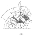
- a shaft-like milling body 1 is provided for a shoulder milling cutter, which has chip chambers 14 at one end at circumferential intervals, the plate seats for Inserts 2 included.
- the indexable insert 2 has a central through-hole 30, a Back, which is shaped as a rectangular frame 32, two opposite end faces 34 and a front side 36 which is shaped as a fillet.
- the sides of the Turning plate 2 have a free surface 9 with a rake surface 10, which is part of is the fillet 36, forms a cutting edge or cutting edge 36.
- the below the Free surface 9 lying side surface 38 forms a contact surface for the system against a bearing surface 16 of the disk seat, which will be discussed further below.
- the cross section of the indexable insert 2 shown in FIG. 1 gives one at the rear trapezoidal recess 18, so that two spaced at the back of the insert Support sections 40, 42 are formed with rear support surfaces 15 which are parallel and run in one plane.
- the cross connections of the support sections 40, 42 to the Ends over the other sections of the frame 32 serve for stability.
- the insert 2 is symmetrical with respect to its longitudinal axis shaped. It is therefore a double-edged insert.
- the plate seat of the chip chamber 14 has a first bearing surface 15 in the form of a elongated narrow surface on the radial outside of the chip chamber 14 on further a second radial bearing surface 16 is formed, which is spaced and in extends at an angle to the first bearing surface 15. It serves to create the side surface 38 of the insert 2.
- the second bearing surface 16 is the wall of an in Cross-section of trapezoidal recess 12.
- the other wall of recess 12 is formed by a wedge-shaped surface 17 which is part of a square or rectangular, truncated pyramid-shaped base 46, which has a threaded bore 24 having.
- the threaded bore 24 serves to receive a fastening screw 3, which is passed through the bore 32 of the insert 2 and this at the insert seat attached.
- one of the two support sections 40 engages in a form-fitting manner the recess 12, while the other support section with its support surface 44 comes to rest against the bearing surface 15 of the milling body 1.
- the cross section the insert 2 is therefore bridge-shaped. Because of the wedge effect of the wedge surface 17 and the corresponding wedge-shaped configuration of the support section 40 Support section effectively set in the recess 12. At the same time fixed contact with the second bearing surface 16.
- the insert 2 is thereby secure held, especially against radial forces, which the fastening screw 3 Load on shear and bend.
- the insert 2 is also present a third bearing surface 23, which represents the axial bearing surface and against the insert 2 is pushed before using the fastening screw is attracted.
- the axis of the threaded bore 24 is placed so that the insert 2 is biased against the axial bearing surface 23. Between the base 46 and there is a distance from the bottom of the recess 18 of the insert 2. The centering the insert 2 therefore takes place essentially via the engagement of a support section 40 with the recess 12 instead. However, this intervention has the consequence that high radial or outward forces due to centrifugal forces and Cutting forces can be absorbed.
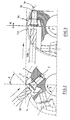
- Fig. 2 shows again a similar arrangement of a milling cutter and an indexable insert as in FIG. 1. Furthermore, a milling tool 50 is indicated for producing the chip chamber 14. It can be seen that a much shorter tool length is required to to produce the chip chamber 14 than, for example, in the tool 50a according to FIG. 3, in which is a conventional shoulder milling cutter, such as that described by DE 43 04 071 has become known and described above.
- Fig. 4 shows the arrangement of the insert 2 with respect to the axes A, B and C. of the router.
- A is the longitudinal axis of the shaft 1 and at the same time the axis of rotation. 4 the installation angle 4 of the insert 2 in the milling body 1 can be seen.
- the installation angle is between 35 and 45 ° in the present case narrow tooth pitch results from the tooth pitch angle 7 according to FIG. 1.
- FIG. 4 also shows the geometry of the indexable insert.
- the insert For example, 2 is ground.
- the large positive axial angle 18 (swirl) results through the chip chambers that are inevitably small when the teeth are narrow 14. Nevertheless, the chips are sufficiently effectively removed axially helically.
- 6 are identical in a section of part of a milling cutter according to the invention Turning plates 2 shown, but which have different contact angles at approximately the same cutting angle. 6 is the angle 45 °, in the middle representation 15 and in the right representation 2 °. In all cases the form-fitting clamping ensures high clamping security, especially against radial forces acting outwards.
Landscapes
- Engineering & Computer Science (AREA)
- Mechanical Engineering (AREA)
- Milling Processes (AREA)
- Gear Processing (AREA)
Applications Claiming Priority (2)
| Application Number | Priority Date | Filing Date | Title |
|---|---|---|---|
| DE19848045 | 1998-10-17 | ||
| DE19848045A DE19848045C2 (de) | 1998-10-17 | 1998-10-17 | Wendeplattenfräser |
Publications (3)
| Publication Number | Publication Date |
|---|---|
| EP0995528A2 true EP0995528A2 (fr) | 2000-04-26 |
| EP0995528A3 EP0995528A3 (fr) | 2002-06-05 |
| EP0995528B1 EP0995528B1 (fr) | 2004-05-06 |
Family
ID=7884887
Family Applications (1)
| Application Number | Title | Priority Date | Filing Date |
|---|---|---|---|
| EP99118133A Expired - Lifetime EP0995528B1 (fr) | 1998-10-17 | 1999-09-11 | Fraise avec des plaquettes de coupe indexables |
Country Status (4)
| Country | Link |
|---|---|
| US (1) | US6203251B1 (fr) |
| EP (1) | EP0995528B1 (fr) |
| AT (1) | ATE265906T1 (fr) |
| DE (2) | DE19848045C2 (fr) |
Families Citing this family (37)
| Publication number | Priority date | Publication date | Assignee | Title |
|---|---|---|---|---|
| FR2837732B1 (fr) * | 2002-03-29 | 2004-09-24 | Stellram | Fraise a plaquettes de coupe amovible pour usinage a tres grande vitesse |
| ITMI20022700A1 (it) * | 2002-12-20 | 2004-06-21 | St Microelectronics Srl | Dispositivo integrato con diodo schottky e transitor mos |
| WO2004078395A1 (fr) * | 2003-03-06 | 2004-09-16 | Rieth, Stephan | Plaquette reversible servant a chanfreiner au moyen d'une tete de fraisage conique |
| US7008146B2 (en) * | 2003-07-21 | 2006-03-07 | Kennametal Inc. | Milling cutter with tangentially mounted inserts |
| IL159157A (en) * | 2003-12-02 | 2008-03-20 | Amir Satran | Rotary slot milling cutter and cutting insert therefor |
| US7004689B2 (en) * | 2004-01-09 | 2006-02-28 | Kennametal Inc. | High-speed milling cutter and insert |
| DE102004001970A1 (de) * | 2004-01-13 | 2005-08-11 | Komet Group Holding Gmbh | Maschinenwerkzeug sowie Grundkörper und Schneidplatte für ein Maschinenwerkzeug |
| US7213623B2 (en) * | 2004-01-20 | 2007-05-08 | Shinn Rickey D | Stump cutting device with load-distributing tooth sockets |
| IL160223A (en) | 2004-02-04 | 2008-11-26 | Carol Smilovici | Double-sided cutting insert and milling cutter |
| US7544022B2 (en) * | 2004-02-16 | 2009-06-09 | Korloy Inc. | Milling cutter |
| AT7667U1 (de) * | 2004-02-16 | 2005-07-25 | Ceratizit Austria Gmbh | Hochgeschwindigkeitsfräser |
| US7708040B2 (en) * | 2004-03-16 | 2010-05-04 | Key Knife, Inc. | High speed planer head |
| JP2005279826A (ja) * | 2004-03-29 | 2005-10-13 | Kyocera Corp | スローアウェイチップ |
| US7070363B2 (en) | 2004-07-15 | 2006-07-04 | Kennametal Inc. | Cutting insert for high-speed milling cutter |
| DE102005011000A1 (de) * | 2005-03-10 | 2006-09-14 | MAPAL Fabrik für Präzisionswerkzeuge Dr. Kress KG | Werkzeug zur Feinbearbeitung von Bohrungsoberflächen |
| DE102005032653B3 (de) | 2005-07-13 | 2006-11-30 | Fette Gmbh | Verfahren zur Herstellung einer formschlüssigen Verbindung zwischen einem Werkzeugeinsatz und einem Werkzeugträger eines rotierenden Werkzeugs |
| US7204662B1 (en) * | 2005-11-17 | 2007-04-17 | Kennametal Inc. | Cutting tool with stress splitter |
| IL178813A (en) * | 2006-10-23 | 2010-06-30 | Iscar Ltd | Tangential cutting insert having a base protrusion seating arrangement |
| SE531502C2 (sv) * | 2007-06-05 | 2009-04-28 | Sandvik Intellectual Property | Verktyg för spånavskiljande bearbetning samt grundkropp och indexerbart skär härför |
| SE531858C2 (sv) * | 2007-12-21 | 2009-08-25 | Sandvik Intellectual Property | Fräsverktyg för spånavskiljande bearbetning, samt skärkropp och grundkropp härför |
| IL188502A (en) | 2007-12-30 | 2012-05-31 | Iscar Ltd | Cutting insert and cutting tool therefor |
| IL195984A0 (en) * | 2008-12-16 | 2009-09-01 | Iscar Ltd | Cutting tool and cutting insert therefor |
| FI122643B (fi) * | 2010-07-07 | 2012-04-30 | Bmh Technology Oy | Murskainroottorin teräpala |
| SE535442C2 (sv) * | 2010-12-28 | 2012-08-07 | Sandvik Intellectual Property | Upprymningsverktyg med han- eller honartade säkringsmedel samt huvud och skär härför |
| US9033621B2 (en) * | 2011-09-19 | 2015-05-19 | Iscar, Ltd. | Cutting insert, cutting body and clamping mechanism of a cutting tool assembly for chip removal |
| DE102011117148B4 (de) * | 2011-10-28 | 2022-05-05 | Kennametal Inc. | Rotationswerkzeug sowie Verfahren zum Herstellen eines Rotationswerkzeuges sowie eines Schneideinsatzes |
| EP2614907B1 (fr) * | 2012-01-13 | 2016-11-30 | Seco Tools Ab | Insert de découpe avec surface de support en biais, porte-outil avec surface de butée en biais et outil de découpe |
| JP6364717B2 (ja) * | 2013-07-30 | 2018-08-01 | 三菱マテリアル株式会社 | フライス用インサートおよび刃先交換式フライス |
| DE102014002062A1 (de) | 2014-02-18 | 2015-08-20 | Peter Schmid | Wendeplattenfräser |
| US9505066B2 (en) * | 2014-08-01 | 2016-11-29 | Kennametal Inc. | Rotary cutting tool with regrindable cutting inserts |
| DE102016111805A1 (de) * | 2016-06-28 | 2017-12-28 | Komet Group Gmbh | Spanabhebendes Maschinenwerkzeug, insbesondere Maschinenreibwerkzeug |
| US10556278B2 (en) | 2016-08-16 | 2020-02-11 | Kennametal Inc. | Tool body for a shell end mill and cutting tool |
| US10525539B2 (en) | 2018-01-08 | 2020-01-07 | Kennametal Inc. | Compression milling cutter with indexable cutting inserts |
| US11453065B2 (en) * | 2019-05-24 | 2022-09-27 | Iscar, Ltd. | Cutting insert having lower anti-slip recess, insert holder and cutting tool |
| AT16933U1 (de) * | 2019-07-11 | 2020-12-15 | Ceratizit Austria Gmbh | Doppelseitiger Schneideinsatz zum Fräsen |
| US20240286207A1 (en) * | 2021-09-01 | 2024-08-29 | Kyocera Corporation | Cutting tool and method for manufacturing machined product |
| JP7645394B2 (ja) * | 2021-10-13 | 2025-03-13 | 京セラ株式会社 | 切削工具及び切削加工物の製造方法 |
Family Cites Families (18)
| Publication number | Priority date | Publication date | Assignee | Title |
|---|---|---|---|---|
| US280148A (en) * | 1883-06-26 | Cutter and holder for lathes | ||
| US947319A (en) * | 1906-03-24 | 1910-01-25 | Wells Brothers Company | Cutter-head. |
| DE2555979C2 (de) * | 1975-12-12 | 1984-06-28 | Montanwerke Walter GmbH, 7400 Tübingen | Bohrwerkzeug für metallische Werkstoffe und dergl. |
| US4189264A (en) * | 1978-09-15 | 1980-02-19 | Fansteel Inc. | Cutting insert and chip control assembly |
| US4315706A (en) * | 1980-04-07 | 1982-02-16 | General Electric Company | Holder assembly for an indexable insert for use in a cutting tool |
| US4682916A (en) * | 1984-04-16 | 1987-07-28 | Briese Leonard A | Cutting insert arrangement |
| DE3446455A1 (de) * | 1984-12-20 | 1986-06-26 | Otto 7210 Rottweil Dieterle | Drehmeissel mit wendeschneidplatte |
| SU1303277A1 (ru) * | 1985-09-30 | 1987-04-15 | Ф.Г.Чернавский, В.И.Семенов, В.А.Шпиньков, В.Г.Дигтенко, М.Д.Кокошко и 0.В.Георгиевский | Режущий инструмент |
| SU1458091A1 (ru) * | 1986-05-13 | 1989-02-15 | Производственное Объединение "Ворошиловградский Тепловозостроительный Завод Им.Октябрьской Революции" | Многогранна режуща пластина |
| AT397219B (de) * | 1990-07-30 | 1994-02-25 | Plansee Tizit Gmbh | Rotierendes spanabhebendes werkzeug |
| DE4304071C1 (de) * | 1993-02-11 | 1994-06-23 | Fette Wilhelm Gmbh | Planfräser |
| DE4330484C2 (de) * | 1993-09-09 | 1995-06-22 | Fette Wilhelm Gmbh | Schälwälzfräser |
| IL113121A0 (en) * | 1995-03-24 | 1995-06-29 | Iscar Ltd | A cutting insert for a milling cutter |
| CA2131066C (fr) * | 1994-08-29 | 2001-01-30 | Denis Johnson | Bras et extremites du dispositif d'ecorcage d'une ecorceuse |
| IL112818A (en) * | 1995-02-28 | 1999-10-28 | Iscar Ltd | Tool holder having a grooved seat |
| DE19701555C2 (de) * | 1997-01-17 | 2000-06-21 | Bernd Dutschke | Fräswerkzeug |
| DE19706377C2 (de) * | 1997-02-19 | 2002-01-24 | Fette Wilhelm Gmbh | Plan- oder Eckfräser |
| US5944456A (en) * | 1997-12-04 | 1999-08-31 | Kennametal Inc. | Three dimensional mill and milling inserts |
-
1998
- 1998-10-17 DE DE19848045A patent/DE19848045C2/de not_active Expired - Fee Related
-
1999
- 1999-09-11 DE DE59909388T patent/DE59909388D1/de not_active Expired - Lifetime
- 1999-09-11 AT AT99118133T patent/ATE265906T1/de not_active IP Right Cessation
- 1999-09-11 EP EP99118133A patent/EP0995528B1/fr not_active Expired - Lifetime
- 1999-09-23 US US09/401,687 patent/US6203251B1/en not_active Expired - Fee Related
Also Published As
| Publication number | Publication date |
|---|---|
| EP0995528B1 (fr) | 2004-05-06 |
| DE19848045A1 (de) | 2000-04-20 |
| EP0995528A3 (fr) | 2002-06-05 |
| DE19848045C2 (de) | 2002-01-31 |
| ATE265906T1 (de) | 2004-05-15 |
| US6203251B1 (en) | 2001-03-20 |
| DE59909388D1 (de) | 2004-06-09 |
Similar Documents
| Publication | Publication Date | Title |
|---|---|---|
| EP0995528B1 (fr) | Fraise avec des plaquettes de coupe indexables | |
| DE69520233T2 (de) | Universelle schneideinsatzaufnahme für tiefschneide- und planfräser | |
| DE69305812T2 (de) | Schneideinsatz für einen Fräser | |
| DE69110236T2 (de) | Ein Schneideinsatz für einen Fräser. | |
| DE69631501T2 (de) | Schneideinsatz | |
| EP2049295B1 (fr) | Outil de frappe pour l'usinage par enlèvement de copeaux de pièces | |
| DE4428310A1 (de) | Befestigungsvorrichtung für ein Werkzeug oder Werkstück | |
| EP1213081B2 (fr) | Outil pour usinage de précision par enlèvement de copeaux | |
| EP0958085A1 (fr) | Plaquette de coupe et outil de fraisage | |
| DE3106120A1 (de) | Werkzeughalterung zur aufnahme einer schneidplatte | |
| DE69709741T2 (de) | Schneidwerkzeug und spannbolzen | |
| DE3215633A1 (de) | Fraeswerkzeug | |
| EP0532532A1 (fr) | Outil de perçage. | |
| AT410188B (de) | Schneidwerkzeug und wendeschneidplatte | |
| EP0264642B1 (fr) | Outil de coupe pour l'usinage de métaux par enlèvement de copeaux en particulier outil de rainurage | |
| EP0631835A1 (fr) | Outil de coupe | |
| EP3223983B1 (fr) | Outil pour l'usinage par enlèvement de copeaux | |
| EP3741483A1 (fr) | Plaquette de coupe, porte-plaquette et dispositif de coupe | |
| EP1213080B1 (fr) | Outil de forage | |
| DE4330484C2 (de) | Schälwälzfräser | |
| EP0144073A2 (fr) | Outil de coupe | |
| DE10333621B4 (de) | Schneideinsatz | |
| AT397219B (de) | Rotierendes spanabhebendes werkzeug | |
| DE3431601A1 (de) | Schneideinsatz mit spanableitung | |
| DE29607927U1 (de) | Schneidelement |
Legal Events
| Date | Code | Title | Description |
|---|---|---|---|
| PUAI | Public reference made under article 153(3) epc to a published international application that has entered the european phase |
Free format text: ORIGINAL CODE: 0009012 |
|
| AK | Designated contracting states |
Kind code of ref document: A2 Designated state(s): AT BE CH CY DE DK ES FI FR GB GR IE IT LI LU MC NL PT SE |
|
| AX | Request for extension of the european patent |
Free format text: AL;LT;LV;MK;RO;SI |
|
| PUAL | Search report despatched |
Free format text: ORIGINAL CODE: 0009013 |
|
| AK | Designated contracting states |
Kind code of ref document: A3 Designated state(s): AT BE CH CY DE DK ES FI FR GB GR IE IT LI LU MC NL PT SE |
|
| AX | Request for extension of the european patent |
Free format text: AL;LT;LV;MK;RO;SI |
|
| RAP1 | Party data changed (applicant data changed or rights of an application transferred) |
Owner name: FETTE GMBH |
|
| 17P | Request for examination filed |
Effective date: 20020913 |
|
| AKX | Designation fees paid |
Designated state(s): AT BE CH CY DE DK ES FI FR GB GR IE IT LI LU MC NL PT SE |
|
| GRAP | Despatch of communication of intention to grant a patent |
Free format text: ORIGINAL CODE: EPIDOSNIGR1 |
|
| GRAS | Grant fee paid |
Free format text: ORIGINAL CODE: EPIDOSNIGR3 |
|
| GRAA | (expected) grant |
Free format text: ORIGINAL CODE: 0009210 |
|
| AK | Designated contracting states |
Kind code of ref document: B1 Designated state(s): AT BE CH CY DE DK ES FI FR GB GR IE IT LI LU MC NL PT SE |
|
| PG25 | Lapsed in a contracting state [announced via postgrant information from national office to epo] |
Ref country code: NL Free format text: LAPSE BECAUSE OF FAILURE TO SUBMIT A TRANSLATION OF THE DESCRIPTION OR TO PAY THE FEE WITHIN THE PRESCRIBED TIME-LIMIT Effective date: 20040506 Ref country code: IE Free format text: LAPSE BECAUSE OF FAILURE TO SUBMIT A TRANSLATION OF THE DESCRIPTION OR TO PAY THE FEE WITHIN THE PRESCRIBED TIME-LIMIT Effective date: 20040506 Ref country code: FI Free format text: LAPSE BECAUSE OF FAILURE TO SUBMIT A TRANSLATION OF THE DESCRIPTION OR TO PAY THE FEE WITHIN THE PRESCRIBED TIME-LIMIT Effective date: 20040506 Ref country code: CY Free format text: LAPSE BECAUSE OF FAILURE TO SUBMIT A TRANSLATION OF THE DESCRIPTION OR TO PAY THE FEE WITHIN THE PRESCRIBED TIME-LIMIT Effective date: 20040506 |
|
| REG | Reference to a national code |
Ref country code: SE Ref legal event code: TRGR |
|
| REG | Reference to a national code |
Ref country code: GB Ref legal event code: FG4D Free format text: NOT ENGLISH |
|
| REG | Reference to a national code |
Ref country code: CH Ref legal event code: NV Representative=s name: ISLER & PEDRAZZINI AG Ref country code: CH Ref legal event code: EP |
|
| REF | Corresponds to: |
Ref document number: 59909388 Country of ref document: DE Date of ref document: 20040609 Kind code of ref document: P |
|
| REG | Reference to a national code |
Ref country code: IE Ref legal event code: FG4D Free format text: GERMAN |
|
| PG25 | Lapsed in a contracting state [announced via postgrant information from national office to epo] |
Ref country code: GR Free format text: LAPSE BECAUSE OF FAILURE TO SUBMIT A TRANSLATION OF THE DESCRIPTION OR TO PAY THE FEE WITHIN THE PRESCRIBED TIME-LIMIT Effective date: 20040806 Ref country code: DK Free format text: LAPSE BECAUSE OF FAILURE TO SUBMIT A TRANSLATION OF THE DESCRIPTION OR TO PAY THE FEE WITHIN THE PRESCRIBED TIME-LIMIT Effective date: 20040806 |
|
| PG25 | Lapsed in a contracting state [announced via postgrant information from national office to epo] |
Ref country code: ES Free format text: LAPSE BECAUSE OF FAILURE TO SUBMIT A TRANSLATION OF THE DESCRIPTION OR TO PAY THE FEE WITHIN THE PRESCRIBED TIME-LIMIT Effective date: 20040817 |
|
| GBT | Gb: translation of ep patent filed (gb section 77(6)(a)/1977) |
Effective date: 20040812 |
|
| PGFP | Annual fee paid to national office [announced via postgrant information from national office to epo] |
Ref country code: GB Payment date: 20040908 Year of fee payment: 6 |
|
| PG25 | Lapsed in a contracting state [announced via postgrant information from national office to epo] |
Ref country code: LU Free format text: LAPSE BECAUSE OF NON-PAYMENT OF DUE FEES Effective date: 20040911 |
|
| PGFP | Annual fee paid to national office [announced via postgrant information from national office to epo] |
Ref country code: CH Payment date: 20040920 Year of fee payment: 6 Ref country code: AT Payment date: 20040920 Year of fee payment: 6 |
|
| PGFP | Annual fee paid to national office [announced via postgrant information from national office to epo] |
Ref country code: FR Payment date: 20040929 Year of fee payment: 6 |
|
| PG25 | Lapsed in a contracting state [announced via postgrant information from national office to epo] |
Ref country code: MC Free format text: LAPSE BECAUSE OF NON-PAYMENT OF DUE FEES Effective date: 20040930 Ref country code: BE Free format text: LAPSE BECAUSE OF NON-PAYMENT OF DUE FEES Effective date: 20040930 |
|
| NLV1 | Nl: lapsed or annulled due to failure to fulfill the requirements of art. 29p and 29m of the patents act | ||
| REG | Reference to a national code |
Ref country code: IE Ref legal event code: FD4D |
|
| ET | Fr: translation filed | ||
| PLBE | No opposition filed within time limit |
Free format text: ORIGINAL CODE: 0009261 |
|
| STAA | Information on the status of an ep patent application or granted ep patent |
Free format text: STATUS: NO OPPOSITION FILED WITHIN TIME LIMIT |
|
| BERE | Be: lapsed |
Owner name: *FETTE G.M.B.H. Effective date: 20040930 |
|
| 26N | No opposition filed |
Effective date: 20050208 |
|
| PG25 | Lapsed in a contracting state [announced via postgrant information from national office to epo] |
Ref country code: IT Free format text: LAPSE BECAUSE OF NON-PAYMENT OF DUE FEES Effective date: 20050911 Ref country code: AT Free format text: LAPSE BECAUSE OF NON-PAYMENT OF DUE FEES Effective date: 20050911 |
|
| PG25 | Lapsed in a contracting state [announced via postgrant information from national office to epo] |
Ref country code: LI Free format text: LAPSE BECAUSE OF NON-PAYMENT OF DUE FEES Effective date: 20050930 Ref country code: CH Free format text: LAPSE BECAUSE OF NON-PAYMENT OF DUE FEES Effective date: 20050930 |
|
| REG | Reference to a national code |
Ref country code: CH Ref legal event code: PL |
|
| GBPC | Gb: european patent ceased through non-payment of renewal fee |
Effective date: 20050911 |
|
| PG25 | Lapsed in a contracting state [announced via postgrant information from national office to epo] |
Ref country code: FR Free format text: LAPSE BECAUSE OF NON-PAYMENT OF DUE FEES Effective date: 20060531 |
|
| REG | Reference to a national code |
Ref country code: FR Ref legal event code: ST Effective date: 20060531 |
|
| BERE | Be: lapsed |
Owner name: *FETTE G.M.B.H. Effective date: 20040930 |
|
| PG25 | Lapsed in a contracting state [announced via postgrant information from national office to epo] |
Ref country code: PT Free format text: LAPSE BECAUSE OF NON-PAYMENT OF DUE FEES Effective date: 20041006 |
|
| PGFP | Annual fee paid to national office [announced via postgrant information from national office to epo] |
Ref country code: SE Payment date: 20090925 Year of fee payment: 11 |
|
| REG | Reference to a national code |
Ref country code: SE Ref legal event code: EUG |
|
| REG | Reference to a national code |
Ref country code: DE Ref legal event code: R082 Ref document number: 59909388 Country of ref document: DE Representative=s name: HAUCK PATENTANWALTSPARTNERSCHAFT MBB, DE Effective date: 20110621 Ref country code: DE Ref legal event code: R082 Ref document number: 59909388 Country of ref document: DE Representative=s name: HAUCK PATENT- UND RECHTSANWAELTE, DE Effective date: 20110621 Ref country code: DE Ref legal event code: R081 Ref document number: 59909388 Country of ref document: DE Owner name: LMT FETTE WERKZEUGTECHNIK GMBH & CO. KG, DE Free format text: FORMER OWNER: FETTE GMBH, 21493 SCHWARZENBEK, DE Effective date: 20110621 |
|
| PG25 | Lapsed in a contracting state [announced via postgrant information from national office to epo] |
Ref country code: SE Free format text: LAPSE BECAUSE OF NON-PAYMENT OF DUE FEES Effective date: 20100912 |
|
| PGFP | Annual fee paid to national office [announced via postgrant information from national office to epo] |
Ref country code: DE Payment date: 20141107 Year of fee payment: 16 |
|
| REG | Reference to a national code |
Ref country code: DE Ref legal event code: R119 Ref document number: 59909388 Country of ref document: DE |
|
| PG25 | Lapsed in a contracting state [announced via postgrant information from national office to epo] |
Ref country code: DE Free format text: LAPSE BECAUSE OF NON-PAYMENT OF DUE FEES Effective date: 20160401 |