EP0995550A2 - Bolzenschneider, insbesondere Mattenschneider - Google Patents
Bolzenschneider, insbesondere Mattenschneider Download PDFInfo
- Publication number
- EP0995550A2 EP0995550A2 EP99118138A EP99118138A EP0995550A2 EP 0995550 A2 EP0995550 A2 EP 0995550A2 EP 99118138 A EP99118138 A EP 99118138A EP 99118138 A EP99118138 A EP 99118138A EP 0995550 A2 EP0995550 A2 EP 0995550A2
- Authority
- EP
- European Patent Office
- Prior art keywords
- bolt
- handling
- cutting jaws
- cutter according
- bolt cutter
- Prior art date
- Legal status (The legal status is an assumption and is not a legal conclusion. Google has not performed a legal analysis and makes no representation as to the accuracy of the status listed.)
- Withdrawn
Links
Images

Classifications
-
- B—PERFORMING OPERATIONS; TRANSPORTING
- B25—HAND TOOLS; PORTABLE POWER-DRIVEN TOOLS; MANIPULATORS
- B25B—TOOLS OR BENCH DEVICES NOT OTHERWISE PROVIDED FOR, FOR FASTENING, CONNECTING, DISENGAGING, OR HOLDING
- B25B7/00—Pliers; Other hand-held gripping tools with jaws on pivoted limbs; Details applicable generally to pivoted-limb hand tools
- B25B7/12—Pliers; Other hand-held gripping tools with jaws on pivoted limbs; Details applicable generally to pivoted-limb hand tools involving special transmission means between the handles and the jaws, e.g. toggle levers, gears
-
- B—PERFORMING OPERATIONS; TRANSPORTING
- B25—HAND TOOLS; PORTABLE POWER-DRIVEN TOOLS; MANIPULATORS
- B25B—TOOLS OR BENCH DEVICES NOT OTHERWISE PROVIDED FOR, FOR FASTENING, CONNECTING, DISENGAGING, OR HOLDING
- B25B7/00—Pliers; Other hand-held gripping tools with jaws on pivoted limbs; Details applicable generally to pivoted-limb hand tools
-
- B—PERFORMING OPERATIONS; TRANSPORTING
- B25—HAND TOOLS; PORTABLE POWER-DRIVEN TOOLS; MANIPULATORS
- B25B—TOOLS OR BENCH DEVICES NOT OTHERWISE PROVIDED FOR, FOR FASTENING, CONNECTING, DISENGAGING, OR HOLDING
- B25B7/00—Pliers; Other hand-held gripping tools with jaws on pivoted limbs; Details applicable generally to pivoted-limb hand tools
- B25B7/02—Jaws
Definitions
- the invention relates to a bolt cutter, in particular for Cutting round bars from steel mesh, comprising two Cutting jaws over joints with two handling levers are connected.
- Bolt cutters of this type are, for example, from EP-B 254 916 known. They are primarily used to cut the round bars of steel mesh, which is laid horizontally in the area Reinforcement mesh is unproblematic. However, since the Cutting jaws and the handling levers of the well-known Bolt cutters lie in one plane, it is difficult to horizontal and vertical round bars to cut through the the walls of the narrow, trough-shaped formwork lie. Cuts on these bars are limited in depth, in the case of horizontal bars by laying the spread handling lever on the formwork edges and at the vertical bars by resting them Handle lever on the opposite edge, the Bolt cutters must be inserted at an angle. Through the Construction of the known bolt cutter mentioned at the beginning with at least twice bent handling levers and at an angle to the center line of the two handling levers Cutting jaws will achieve some improvement, though however, especially not with vertical bars at depth is sufficient.
- the invention has for its object a bolt cutter of the type outlined at the beginning, with which it is possible to have round bars lying at great depth these are aligned horizontally or vertically without Difficulty severing.
- this object is achieved in that the Cutting jaws lie in a plane that is essentially rectangular to the level of the handling lever.
- the bolt cutter When the bolt cutter is used to cut vertical bars it is intended that the level of Cutting jaws level the handle in a line cuts that parallel to the connecting straight line of the joints runs between the cutting jaws and the handling levers. This means that when the bolt cutter is used vertically Cutting jaws from the handling levers in a horizontal Level down.
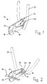
- FIGs 1 and 2 show a first embodiment of the Invention in which the cutting head 10 of a bolt cutter for Cutting through horizontal round bars 12 (FIG. 2) is shown.
- Two flat, plate-shaped cutting jaws 14 are each one horizontal bolt 16 articulated on a pair of connecting straps 18, as close as possible to the wedge-shaped cutting edges 20.
- the cutting jaws 14 instead to train for wedge cutting for shear cutting.
- the Cutting jaws 14 articulated with two handling levers 22 connected.
- the handling levers 22 extend approximately vertically above, while in the open position of FIG. 2 are spread.
- embodiments 1 and 2 and 3 and 4 are the both ends of the cutting jaws facing away from the cutting edges 20 14 designed as a round bolt 24.
- the one in FIGS. 1 and 2 lower round bolt 24 forms a fixed pivot axis for the two handling levers 22, at their lower end a mounting bracket 26 is firmly attached. Above this Bearing bracket 26 is another from each handling lever 22 Tab 28 from a connecting tab 30 to the upper Round bolt 24 is articulated.
- the two round bolts 24 and thus the two cutting jaws 14 are in one vertical plane, in which also between the two Handling levers 22 lying center line 32 lies.
- the lower round bolt 24 forms a fixed pivot axis for the two handling levers 22, while the upper round bolt 24 is vertical on the center line 32 is movable.
- Figure 1 shows that when closed of the two cutting jaws 14, the connecting tabs 30 one form an acute angle.
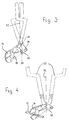
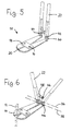
- FIGS. 5 and 6 and 7 and 8 show the cutting heads 10 of bolt cutters for cutting vertically aligned round bar 12 (see FIG. 6).
- the two cutting jaws 14 with a vertical Use the bolt cutter in a horizontal plane so that the plane of the cutting jaws 14 the plane of the handling levers 22 cuts in a straight line 38 that is parallel to Straight connecting line 36 of the joints between the cutting jaws 14 and the handling levers 22.
- FIGS 5 and 6 show that here too the two Cutting jaws 14 each have a bolt 16 on one Connecting strap pair 18 are articulated, this here horizontally lies. Of the ends facing away from the cutting edges 20 Cutting jaws 14 protrude upward from the articulated eyes 40, fork-shaped ends 42 of the handling lever 22 over a pin 44 are pivotally connected.
- Figures 5 and 6 show a modified embodiment, at which is a handling lever 22 - here the right handling lever - the pivot axis 46 carries while from the opposite Handle lever 22 protrudes a length-adjustable support pin 48 the end of which is articulated on the horizontal pivot axis 46 is.
Landscapes
- Engineering & Computer Science (AREA)
- Mechanical Engineering (AREA)
- Scissors And Nippers (AREA)
- Accessories And Tools For Shearing Machines (AREA)
Abstract
Description
Claims (12)
- Bolzenschneider, insbesondere zum Durchtrennen von Rundeisen von Baustahlmatten, umfassend zwei Schneidbacken, die über Gelenke mit zwei Handhabungshebeln verbunden sind, dadurch gekennzeichnet, daß die Schneidbacken (14) in einer Ebene liegen, die i.w. rechtwinklig zur Ebene der Handhabungshebel (22) verläuft.
- Bolzenschneider nach Anspruch 1, dadurch gekennzeichnet, daß die zwischen den beiden Handhabungshebeln (22) in deren gemeinsamer Ebene liegende Mittellinie (32) in der Ebene der Schneidbacken (14) liegt.
- Bolzenschneider nach Anspruch 2, dadurch gekennzeichnet, daß die mit den Handhabungshebeln (22) verbundenen Enden der Schneidbacken (14) als Rundbolzen (24) ausgebildet sind, die Teile der die Handhabungshebel (22) miteinander verbindenden Gelenke sind.
- Bolzenschneider nach Anspruch 3, dadurch gekennzeichnet, daß einer der beiden Rundbolzen (24) eine ortsfeste Schwenkachse der beiden Handhabungshebel (22) bildet, während der andere Rundbolzen (24) eine auf der Mittellinie (32) verschiebbare Schwenkachse für zwei an den Handhabungshebeln (22) angelenkte Verbindungslaschen (30) bildet.
- Bolzenschneider nach Anspruch 4, dadurch gekennzeichnet, daß die Verbindungslaschen (30) im geschlossenen Zustand der Schneidbacken (14) einen spitzen Winkel bilden.
- Bolzenschneider nach Anspruch 1, dadurch gekennzeichnet, daß die Ebene der Schneidbacken (14) die Ebene der Handhabungshebel (22) in einer Linie (38) schneidet, die parallel zur Verbindungsgeraden (36) der Gelenke zwischen den Schneidbacken (14) und den Handhabungshebeln (22) verläuft.
- Bolzenschneider nach Anspruch 6, dadurch gekennzeichnet, daß von den mit den Handhabungshebeln (22) verbundenen Enden der Schneidbacken (14) Gelenkaugen (40) abstehen, die mit den gabelförmig ausgebildeten Enden (42) der Handhabungshebel (22) schwenkbeweglich verbunden sind.
- Bolzenschneider nach Anspruch 7, dadurch gekennzeichnet, daß die beiden Handhabungshebel (22) über eine ortsfeste Schwenkachse (46) miteinander verbunden sind.
- Bolzenschneider nach Anspruch 8, dadurch gekennzeichnet, daß an der an einem Handhabungshebel (22) ausgebildeten Schwenkachse (46) ein vom gegenüberliegenden Handhabungshebel (22) abstehender, längenverstellbarer Stützbolzen (48) angelenkt ist.
- Bolzenschneider nach einem der vorhergehenden Ansprüche, dadurch gekennzeichnet, daß die Schneidbacken (14) über je einen Bolzen (16) an einem Verbindungslaschenpaar (18) angelenkt sind.
- Bolzenschneider nach einem der Ansprüche 1 bis 9, dadurch gekennzeichnet, daß die Schneidbacken (14) über einen Schwenkbolzen (16') miteinander verbunden sind.
- Bolzenschneider nach einem der vorhergehenden Ansprüche, dadurch gekennzeichnet, daß die Handhabungshebel (22) einen abgekröpften Verlauf haben.
Applications Claiming Priority (2)
| Application Number | Priority Date | Filing Date | Title |
|---|---|---|---|
| DE1998148749 DE19848749A1 (de) | 1998-10-22 | 1998-10-22 | Bolzenschneider, insbesondere Mattenschneider |
| DE19848749 | 1998-10-22 |
Publications (2)
| Publication Number | Publication Date |
|---|---|
| EP0995550A2 true EP0995550A2 (de) | 2000-04-26 |
| EP0995550A3 EP0995550A3 (de) | 2002-09-04 |
Family
ID=7885312
Family Applications (1)
| Application Number | Title | Priority Date | Filing Date |
|---|---|---|---|
| EP99118138A Withdrawn EP0995550A3 (de) | 1998-10-22 | 1999-09-11 | Bolzenschneider, insbesondere Mattenschneider |
Country Status (2)
| Country | Link |
|---|---|
| EP (1) | EP0995550A3 (de) |
| DE (1) | DE19848749A1 (de) |
Cited By (1)
| Publication number | Priority date | Publication date | Assignee | Title |
|---|---|---|---|---|
| FR2876932A1 (fr) * | 2004-10-22 | 2006-04-28 | Mob Outil Sa | Dispositif de coupe du type coupe boulons |
Family Cites Families (5)
| Publication number | Priority date | Publication date | Assignee | Title |
|---|---|---|---|---|
| US3089240A (en) * | 1961-07-06 | 1963-05-14 | Peter S Vosbikian | Shears |
| DE3626078A1 (de) * | 1986-07-31 | 1988-02-11 | Ver Beckersche Werkzeugfab | Hebeluebersetzte zange fuer enge oeffnungen |
| DE9204637U1 (de) * | 1992-04-04 | 1992-07-16 | GÖHRIG, Gudrun | Bolzen- oder Mattenschneider |
| US5339712A (en) * | 1993-10-25 | 1994-08-23 | Daryoush Keyvani | Hand tool having offset work elements |
| AU7128996A (en) * | 1995-09-26 | 1997-04-17 | Knipex-Werk | Front-cutting nippers |
-
1998
- 1998-10-22 DE DE1998148749 patent/DE19848749A1/de not_active Withdrawn
-
1999
- 1999-09-11 EP EP99118138A patent/EP0995550A3/de not_active Withdrawn
Cited By (1)
| Publication number | Priority date | Publication date | Assignee | Title |
|---|---|---|---|---|
| FR2876932A1 (fr) * | 2004-10-22 | 2006-04-28 | Mob Outil Sa | Dispositif de coupe du type coupe boulons |
Also Published As
| Publication number | Publication date |
|---|---|
| EP0995550A3 (de) | 2002-09-04 |
| DE19848749A1 (de) | 2000-04-27 |
Similar Documents
| Publication | Publication Date | Title |
|---|---|---|
| DE2514516B2 (de) | Klemmhalter für Hosenträger u.dgl. | |
| EP0126862A1 (de) | Energieführungskette | |
| DE2948931A1 (de) | Scheiben-wischblaetter fuer fahrzeuge | |
| EP0666131B1 (de) | Schere für schwere Beanspruchungen, insbesondere Abbruch- bzw. Schrottschere | |
| DE3924915A1 (de) | Langlaufskibindung der scharnierbauart | |
| DE3311219A1 (de) | Vorrichtung zum verbinden eines wischerarmes mit einem wischerblatt | |
| DE19841521A1 (de) | Schneide-/Brechvorrichtung | |
| DE1913606A1 (de) | Kuppplungsvorrichtung fuer zweiteilige Skier | |
| DE3016631A1 (de) | Scheibenwischer | |
| DE1652665A1 (de) | Haltevorrichtung fuer Schneidwerkzeuge,insbesondere an Drehbaenken | |
| DE60005483T2 (de) | Türkonstruktion | |
| DE3117233A1 (de) | Gelenkbolzen-adapter fuer einen scheibenwischer | |
| DE2721107A1 (de) | Vorrichtung zur verbindung eines arbeitswerkzeuges an einem tragarm, insbesondere an einem holm | |
| EP0995550A2 (de) | Bolzenschneider, insbesondere Mattenschneider | |
| DE69007689T2 (de) | Schnappverbindungsanordnung, insbesondere für elektrische Schaltschränke. | |
| DE2233336A1 (de) | Befestigungsanordnung zum verbinden eines messers mit einer maeher-messerwelle | |
| AT390485B (de) | Einrichtung zur kupplung von zwei zueinander in einem winkel befindlichen elementen | |
| CH620392A5 (en) | Bolt cutter. | |
| DE3402544C2 (de) | Bolzenschneider | |
| DE69803558T2 (de) | Bügelpresse | |
| DE3639738A1 (de) | Mechanismus zum versetzen und verriegeln eines mittels haken zwischen pfosten gehaltenen flaechigen teils | |
| DE2508274A1 (de) | Geruestverbindung | |
| DE19959940B4 (de) | Lastträgerfuß | |
| DE2821235C2 (de) | Türzarge | |
| DE2702364C3 (de) | Bolzenschneider |
Legal Events
| Date | Code | Title | Description |
|---|---|---|---|
| PUAI | Public reference made under article 153(3) epc to a published international application that has entered the european phase |
Free format text: ORIGINAL CODE: 0009012 |
|
| AK | Designated contracting states |
Kind code of ref document: A2 Designated state(s): AT BE CH CY DE DK ES FI FR GB GR IE IT LI LU MC NL PT SE |
|
| AX | Request for extension of the european patent |
Free format text: AL;LT;LV;MK;RO;SI |
|
| PUAL | Search report despatched |
Free format text: ORIGINAL CODE: 0009013 |
|
| AK | Designated contracting states |
Kind code of ref document: A3 Designated state(s): AT BE CH CY DE DK ES FI FR GB GR IE IT LI LU MC NL PT SE |
|
| AX | Request for extension of the european patent |
Free format text: AL;LT;LV;MK;RO;SI |
|
| RIC1 | Information provided on ipc code assigned before grant |
Free format text: 7B 25B 7/00 A, 7B 25B 7/02 B, 7B 26B 17/00 B, 7B 23D 29/02 B |
|
| STAA | Information on the status of an ep patent application or granted ep patent |
Free format text: STATUS: THE APPLICATION IS DEEMED TO BE WITHDRAWN |
|
| 18D | Application deemed to be withdrawn |
Effective date: 20020402 |