EP0995554A2 - Vorrichtung zur Befestigung eines Bodenbearbeitungsgerätes, insbesondere Besen-, Schrubber-, Feuchtwischkörpers oder dergleichen - Google Patents
Vorrichtung zur Befestigung eines Bodenbearbeitungsgerätes, insbesondere Besen-, Schrubber-, Feuchtwischkörpers oder dergleichen Download PDFInfo
- Publication number
- EP0995554A2 EP0995554A2 EP99117867A EP99117867A EP0995554A2 EP 0995554 A2 EP0995554 A2 EP 0995554A2 EP 99117867 A EP99117867 A EP 99117867A EP 99117867 A EP99117867 A EP 99117867A EP 0995554 A2 EP0995554 A2 EP 0995554A2
- Authority
- EP
- European Patent Office
- Prior art keywords
- tillage implement
- clamping
- sliding element
- stem
- tensioning
- Prior art date
- Legal status (The legal status is an assumption and is not a legal conclusion. Google has not performed a legal analysis and makes no representation as to the accuracy of the status listed.)
- Granted
Links
Images



Classifications
-
- B—PERFORMING OPERATIONS; TRANSPORTING
- B25—HAND TOOLS; PORTABLE POWER-DRIVEN TOOLS; MANIPULATORS
- B25G—HANDLES FOR HAND IMPLEMENTS
- B25G3/00—Attaching handles to the implements
- B25G3/38—Hinged, pivoted, swivelling, or folding joints
-
- B—PERFORMING OPERATIONS; TRANSPORTING
- B25—HAND TOOLS; PORTABLE POWER-DRIVEN TOOLS; MANIPULATORS
- B25G—HANDLES FOR HAND IMPLEMENTS
- B25G3/00—Attaching handles to the implements
Definitions
- the invention relates to a device for fastening a soil tillage implement, especially a broom, Scrubber, damp mop or the like on one Stem consisting of at least two in recesses of the Tillage implement insertable fasteners, those on the soil tillage implement Are arranged at the end of the device and at least one in a further recess (s) of the soil tillage implement insertable and by means of a clamping device tensionable, resilient clamping element, the clamping element (s) in an axis parallel to the Longitudinal axis of the tillage implement can be swiveled is (are).
- the object of the invention is to provide a device which avoids the aforementioned disadvantages and which the assembly as well as disassembly of the tillage implement a stem is made considerably easier.
- This object is achieved in that the tensioning device for tensioning or relaxing the clamping element (s) in the further recess (s) of the Soil cultivator movable in the longitudinal direction of the stick is.
- This training initially has the advantage that the clamping elements are fixed in the untensioned state are, so that the tillage implement facing Ends of the clamping elements with the ends of the fastening elements swear.
- the clamping is made considerably easier because the tensioning device is displaceable in the longitudinal direction and is easier to operate.
- the user can put the end of the stem on a floor and the tensioning device with both hands towards the Move the stem end.
- At least two clamping elements are preferably provided, which engage in the other recesses, since such a particularly good fixation of the tillage implement on Stem is guaranteed.
- the fasteners can be at least in some areas parallel to the longitudinal axis of the tillage implement extending support rods may be formed. It offers that the holding rods are sufficiently spaced at the ends are spaced so that the tillage implement is adequately fixed to the handle by means of the device.
- the holding rods can be parallel in the area of the tensioning device to the longitudinal direction of the stem and at a distance from each other run.
- the clamping elements can expediently as resilient Wires be formed, each resilient wire at least with a winding around the parallel to the longitudinal axis of the Tillage areas of the support rods is led. On the one hand, this ensures that an axis of rotation for the trained as resilient wires Clamping elements is created and on the other hand the clamping elements are adequately guided.
- the resilient wires at the ends facing the stem have a sliding element which in a recess of Sheath is slidably mounted.
- the sliding element emerges from the state of the resilient wires the recess of the casing.
- the distance between at least the holding rods in the area of the tensioning device slightly larger than the width of the sliding element his.
- the resilient wires in the sheath can be the sliding element have a latch. Once the sliding element assumes a certain position, this snaps with the Latch on a ledge, so that a relaxation the tensioning device is prevented.
- the sliding element can expediently have recesses for Have insertion of the ends of the resilient wires.
- the ends of the inserted into the sliding element be resilient wires bent and essentially by means of a arranged transversely to the resilient wires Pin fixed. This enables easy assembly or later disassembly of the device according to the invention.
- a stop may be provided.
- the stem For fastening the holding rods of the device according to the invention in the stem can be substantially cylindrical shaped body may be provided. This is with pushed the support rods into one end of the stem.
- the body can have longitudinal grooves into which the Holding rods are stored.
- the depth of the longitudinal grooves is slightly less than the diameter of the support rods. This ensures that the stem is only slightly in the area of the support rods is expanded so that a secure fixation of the Device according to the invention guaranteed on the stem and thus, for example, twisting is prevented.
- the body on the soil tillage implement facing end at least in some areas Have a head start.
- the support rods can be used to simplify the construction with the ends facing away from the tillage implement a strap to be connected together, and the body can on the tillage implement facing away Have a corresponding recess.
- the end of the tillage implement facing away Body have at least one phase, preferably rotating.
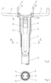
- Fig. 1 shows a device for attaching a soil tillage implement 1 such as B. broom, scrubber body, Puller or the like, which i.a. in Fig. 4 is shown.
- the device is on a End of a stem 2.
- the device On the stem 2 facing away On the side, the device has two designed as holding rods Fasteners 3, each fastener 3 shows a region parallel to the longitudinal axis of the Soil cultivation device 1 has.
- the ends of the fasteners 3 are in the direction of the soil tillage implement 1 angled.
- the fasteners 3 are parallel and in Spaced from each other.
- the fasteners are on the end 3 connected to each other in the stem 2 and are supported by a body 5 in the end of the stem 2 held.
- the tillage implement 1 to the fastening elements 3 are designed as resilient wires
- Clamping elements 6 are provided, the ends 7 of which are angled are.
- the clamping elements 6 are at least one each Winding 8 around the parallel to the longitudinal axis of the soil tillage implement 1 trending areas of the fasteners 3 led.
- the clamping elements 6 rotatably mounted, so that depending on the position of the The position of the clamping device 4 can be changed.
- the clamping device 4 can for a secure grip have structured surface 9.
- the soil tillage implement 1 opposite ends 10 of the clamping elements 6 into a sliding element 11.
- This sliding element 11 is in the tensioned state of the clamping elements 6 between the fastening elements 3 arranged.
- the distance between the two fasteners 3 in the area of Sliding element 11 larger than the width of the sliding element Be 11.
- the body 5 inserted into the stem 2, as in FIG. 3 emerges, has longitudinal grooves 12, two in opposite Longitudinal grooves 12 which are designed as holding rods Fasteners 3 are stored. Because the diameter of the fasteners 3 greater than the depth of the Is longitudinal grooves 12, the body 5 has in the region of the fasteners 3 surveys. At these surveys the stem 2 is expanded so that the device is secure is held on the stem 2.
- the tensioning device 4 designed as a casing shown.
- the soil tillage implement 1 is in the unstressed condition on the handle 2.
- the clamping elements 6 are in recesses 13 of the tillage implement 1 introduced.
- the angled end 7 of each clamping element 6 is still in this state Recess 13, so that the tillage implement 1 at any time is removable again.
- the sliding element 11 is arranged. So that Sliding element is held securely at the ends 10 are the ends 10 bent and by means of a pin 14 on the Sliding element 11 attached.
- the sliding element 11 has a sliding surface 15, so that the sliding element 11 easily in a recess 16 the clamping device 4 is movable. Furthermore, on the Sliding element 11, a locking lug 17 is provided to engage the sliding element 11 in the tensioned state enable.
- a stop 18 is provided.
- Fig. 5 shows the position of the clamping elements 6 in the semi-clamped Status. It is clearly recognizable that the clamping elements 6 with the ends 7 the edges of the recess 13 in the soil tillage implement 1, so that Soil cultivator 1 is already fixed on stick 2 is.
- the sliding element 11 has changed due to the movement the tensioning device 4 in the direction of arrow 19 through the Recess 16 more in the middle of the clamping device 4th emotional.
- Fig. 6 shows the end position of the clamping device 4.
- the sliding element 11 disappears almost completely in the recess 16.
- the tillage implement 1 can be removed from the stem 2 again the tensioning device 4 moves in the direction of the arrow 20, so that the sliding element 11 comes out of the recess 16 emerges and the ends 7 of the clamping elements 6 no longer grasp the tillage implement 1.
- Fig. 7 is the bracket again as resilient Wires formed clamping elements 6 in the sliding element 11 shown.
- the bent ends of the clamping elements 6 are fixed by the pin 14.
- the sliding elements 11, which is in the untensioned position, passes through the recess 16 from the clamping device 4th out.
- the fasteners 3 are in grooves 21, the are provided on the inner surface of the clamping device 4, guided.
- the clamping device 4 has the outside structured surface 9.
- Fig. 8 shows the body 5, which is designed as a bracket Fastening elements 3 fixed on the handle 2.
- the body 5 on the in Direction of the tillage implement 1 directed end a projection 22.
- a recess 23 is provided so that the as Bracket-shaped ends of the fasteners 3 completely engage in body 5.
- the body 5 has the opposite of the projection 22 End phase 24.
- the longitudinal grooves 12 shown in FIG. 9 serve only to save material. Therefore, the projection 22 runs in Area of these longitudinal grooves 12 without interruption.
- the longitudinal grooves 12 have the take the fasteners 3, a cross section with a constant radius in the groove bottom while the longitudinal grooves 12, which are introduced to save material are wedge-shaped cross-section.
Landscapes
- Engineering & Computer Science (AREA)
- Mechanical Engineering (AREA)
- Soil Working Implements (AREA)
- Cleaning Implements For Floors, Carpets, Furniture, Walls, And The Like (AREA)
Abstract
Description
- Fig. 1
- eine Draufsicht auf eine erfindungsgemäße Vorrichtung mit einem Stiel ohne ein Bodenbearbeitungsgerät,
- Fig. 2
- einen Schnitt durch den Gegenstand nach Fig. 1,
- Fig. 3
- einen Schnitt in Richtung III-III durch den Gegenstand nach Fig. 2,
- Fig. 4
- einen Längsschnitt durch den Gegenstand nach Fig. 1 um 90° gedreht mit einem auf die Vorrichtung aufgesteckten Bodenbearbeitungsgerät im ungespannten Zustand,
- Fig. 5
- den Gegenstand nach Fig. 4 im halbgespannten Zustand,
- Fig. 6
- den Gegenstand gemäß Fig. 4 im gespannten Zustand,
- Fig. 7
- einen Schnitt in Richtung VII-VII durch den Gegenstand nach Fig. 4,
- Fig. 8
- eine Seitenansicht auf einen Körper,
- Fig. 9
- den Körper nach Fig. 8 um 90° gedreht und
- Fig. 10
- einen Schnitt in Richtung X-X durch den Gegenstand nach Fig. 8.
Claims (19)
- Vorrichtung zur Befestigung eines Bodenbearbeitungsgerätes (1), insbesondere Besen-, Schrubber-, Feuchtwischkörpers oder dergleichen an einem Stiel (2) bestehend aus zumindest zwei in Ausnehmungen des Bodenbearbeitungsgerätes (1) einführbaren Befestigungselementen (3), die an dem dem Bodenbearbeitungsgerät (1) zugewandten Ende der Vorrichtung angeordnet sind sowie aus zumindest einem in einer weiteren Ausnehmung(en) (13) des Bodenbearbeitungsgerätes (1) einführbaren und mittels einer Spanneinrichtung (4) spannbaren, federnd ausgebildeten Klemmelement (6), wobei das(die) Klemmelement(e) (6) in einer Achse parallel zur Längsachse des Bodenbearbeitungsgerätes (1) schwenkbar ist(sind), dadurch gekennzeichnet, dass die Spanneinrichtung (4) zum Spannen bzw. zum Entspannen des(der) Klemmelementes(Klemmelemente) (6) in der(den) weiteren Ausnehmung(en) (13) des Bodenbearbeitungsgerätes (1) in Längsrichtung des Stiels (2) verschieblich ist.
- Vorrichtung nach Anspruch 1, dadurch gekennzeichnet, dass die die dem Bodenbearbeitungsgerät (1) abgewandten Enden (10) der Klemmelemente (6) spannende Spanneinrichtung (4) als eine die Vorrichtung zumindest teilweise umfassende Ummantelung, insbesondere Hülse ausgebildet ist.
- Vorrichtung nach Anspruch 2, dadurch gekennzeichnet, dass die als Ummantelung ausgebildete Spanneinrichtung (4) die Vorrichtung vollständig umfasst.
- Vorrichtung nach einem der Ansprüche 1 bis 3, dadurch gekennzeichnet, dass die Befestigungselemente (3) als zumindest bereichsweise parallel zur Längsachse des Bodenbearbeitungsgerätes (1) verlaufende Haltestäbe ausgebildet sind.
- Vorrichtung nach Anspruch 4, dadurch gekennzeichnet, dass die Haltestäbe im Bereich der Spanneinrichtung (4) parallel zur Längsrichtung des Stiels (2) und im Abstand zueinander verlaufen.
- Vorrichtung nach einem der Ansprüche 1 bis 5, dadurch gekennzeichnet, dass die Klemmelemente (6) als federnde Drähte ausgebildet sind, wobei jeder federnde Draht zumindest mit einer Wicklung (8) um die parallel zur Längsachse des Bodenbearbeitungsgerätes (1) verlaufenden Bereiche der Haltestäbe geführt ist.
- Vorrichtung nach Anspruch 6, dadurch gekennzeichnet, dass die federnden Drähte an den den Stiel (2) zugewandten Enden (10) ein Schiebelement (11) aufweisen, das in einer Ausnehmung (16) der Ummantelung verschiebbar gelagert ist.
- Vorrichtung nach Anspruch 7, dadurch gekennzeichnet, dass der Abstand zwischen den Haltestäben im Bereich der Spanneinrichtung (4) zumindest etwas größer als die Breite des Schiebelementes (11) ist.
- Vorrichtung nach Anspruch 7 oder 8, dadurch gekennzeichnet, dass das Schiebelement (11) eine gekrümmt ausgebildete Gleitfläche (15) zum Gleiten in der Spanneinrichtung (4) aufweist.
- Vorrichtung nach einem der Ansprüche 7 bis 9, dadurch gekennzeichnet, dass das Schiebelement (11) eine Rastnase (17) zur Fixierung des Schiebelementes (11) im gespannten Zustand der federnden Drähte aufweist.
- Vorrichtung nach einem der Ansprüche 7 bis 10, dadurch gekennzeichnet, dass das Schiebelement (11) Aussparungen zum Einführen der Enden (10) der federnden Drähte aufweist.
- Vorrichtung nach Anspruch 11, dadurch gekennzeichnet, dass die in das Schiebelement (11) eingeführten Enden (10) der federnden Drähte umgebogen sind und mittels eines im wesentlichen quer zu den federnden Drähten angeordneten Stiftes (14) fixiert sind.
- Vorrichtung nach einem der Ansprüche 2 bis 12, dadurch gekennzeichnet, dass in der Ummantelung ein Anschlag (18) vorgesehen ist.
- Vorrichtung nach einem der Ansprüche 3 bis 13, dadurch gekennzeichnet, dass zur Befestigung der Haltestäbe in dem Stiel (2) ein im wesentlichen zylinderförmig geformter Körper (5) vorgesehen ist.
- Vorrichtung nach Anspruch 14, dadurch gekennzeichnet, dass der Körper (5) Längsnuten (12) aufweist.
- Vorrichtung nach Anspruch 15, dadurch gekennzeichnet, dass die Tiefe der Längsnuten (12) geringfügig geringer als der Durchmesser der Haltestäbe ist.
- Vorrichtung nach einem der Ansprüche 14 bis 16, dadurch gekennzeichnet, dass der Körper (5) an dem dem Bodenbearbeitungsgerät (1) zugewandten Ende zumindest bereichsweise einen Vorsprung (22) aufweist.
- Vorrichtung nach einem der Ansprüche 3 bis 16, dadurch gekennzeichnet, dass die Haltestäbe mit den dem Bodenbearbeitungsgerät (1) abgewandten Enden zu einem Bügel miteinander verbunden sind und der Körper (5) auf der dem Bodenbearbeitungsgerät (1) abgewandten Stirnfläche eine entsprechende Ausnehmung (23) aufweist.
- Vorrichtung nach einem der Ansprüche 13 bis 18, dadurch gekennzeichnet, dass das dem Bodenbearbeitungsgerät (1) abgewandte Ende des Körpers (5) zumindest eine Phase (24) aufweist.
Applications Claiming Priority (2)
| Application Number | Priority Date | Filing Date | Title |
|---|---|---|---|
| DE29818801U DE29818801U1 (de) | 1998-10-22 | 1998-10-22 | Vorrichtung zur Befestigung eines Bodenbearbeitungsgerätes, insbesondere Besen-, Schrubber-, Feuchtwischkörpers o.dgl. |
| DE29818801U | 1998-10-22 |
Publications (3)
| Publication Number | Publication Date |
|---|---|
| EP0995554A2 true EP0995554A2 (de) | 2000-04-26 |
| EP0995554A3 EP0995554A3 (de) | 2000-09-20 |
| EP0995554B1 EP0995554B1 (de) | 2004-04-21 |
Family
ID=8064212
Family Applications (1)
| Application Number | Title | Priority Date | Filing Date |
|---|---|---|---|
| EP99117867A Expired - Lifetime EP0995554B1 (de) | 1998-10-22 | 1999-09-10 | Vorrichtung zur Befestigung eines Bodenbearbeitungsgerätes, insbesondere Besen-, Schrubber-, Feuchtwischkörpers oder dergleichen |
Country Status (3)
| Country | Link |
|---|---|
| EP (1) | EP0995554B1 (de) |
| AT (1) | ATE264730T1 (de) |
| DE (2) | DE29818801U1 (de) |
Cited By (1)
| Publication number | Priority date | Publication date | Assignee | Title |
|---|---|---|---|---|
| EP1952955A1 (de) * | 2007-01-31 | 2008-08-06 | Coronet-International GmbH & Co. KG | Vorrichtung zur lösbaren Anbringung eines Reinigungsgerätes |
Families Citing this family (2)
| Publication number | Priority date | Publication date | Assignee | Title |
|---|---|---|---|---|
| DE19930778A1 (de) * | 1999-07-03 | 2001-01-04 | Ferdinand Liosar | Wischmopplatte mit Bajonett-Schwenkarretierung |
| DE102006034321A1 (de) * | 2006-07-21 | 2008-01-24 | Bürstenmann GmbH | Verbindungssystem für stielgeführte Handgeräte |
Family Cites Families (3)
| Publication number | Priority date | Publication date | Assignee | Title |
|---|---|---|---|---|
| FR2238565A1 (en) * | 1973-07-24 | 1975-02-21 | Peugeot Aciers Et Outillage | Coupling device for garden tool handle and head - U-shaped rod on head is wedged and bolted in position |
| DE7734201U1 (de) * | 1977-11-08 | 1978-02-09 | Roman Dietsche, Kg, 7868 Todtnau | Loesbare stielbefestigung fuer besen oder schrubber |
| DE9112122U1 (de) | 1991-09-28 | 1991-11-14 | Watz, Richard, 6334 Aßlar | Befestigungsvorrichtung für Besenkörper o.dgl. an einem Stiel |
-
1998
- 1998-10-22 DE DE29818801U patent/DE29818801U1/de not_active Expired - Lifetime
-
1999
- 1999-09-10 DE DE59909226T patent/DE59909226D1/de not_active Expired - Lifetime
- 1999-09-10 EP EP99117867A patent/EP0995554B1/de not_active Expired - Lifetime
- 1999-09-10 AT AT99117867T patent/ATE264730T1/de not_active IP Right Cessation
Cited By (1)
| Publication number | Priority date | Publication date | Assignee | Title |
|---|---|---|---|---|
| EP1952955A1 (de) * | 2007-01-31 | 2008-08-06 | Coronet-International GmbH & Co. KG | Vorrichtung zur lösbaren Anbringung eines Reinigungsgerätes |
Also Published As
| Publication number | Publication date |
|---|---|
| DE59909226D1 (de) | 2004-05-27 |
| EP0995554B1 (de) | 2004-04-21 |
| EP0995554A3 (de) | 2000-09-20 |
| DE29818801U1 (de) | 1998-12-24 |
| ATE264730T1 (de) | 2004-05-15 |
Similar Documents
| Publication | Publication Date | Title |
|---|---|---|
| DE69718446T2 (de) | Haarschneidesystem mit einer haarschneidevorrichtung und einer kammvorrichtung, die an der haarschneidevorrichtung befestigt werden kann und die zwei federbelastete kammabschnitte hat | |
| DE3687293T2 (de) | Vollstaendig gegliederte lagerungsvorrichtung. | |
| EP0868128B1 (de) | Stockgriff | |
| EP0203082A1 (de) | Vorrichtung zum reinigen der zahnzwischenräume. | |
| WO1999053987A1 (de) | Flexible katheder-hülsenführung | |
| DE3526684C1 (de) | Spannvorrichtung zum Einspannen von insbesondere Zahnwerkzeugen | |
| DE102020127061A1 (de) | Umschaltelement für Ratschenschlüssel | |
| EP0260671B1 (de) | Schläger für Ballspiele, insbesondere Tennisspiele, sowie Bespannvorrichtung hierzu | |
| DE3618973A1 (de) | Hoeheneinstellbare vorrichtung an einem sicherheitsgurt fuer kraftfahrzeuge | |
| EP0995554B1 (de) | Vorrichtung zur Befestigung eines Bodenbearbeitungsgerätes, insbesondere Besen-, Schrubber-, Feuchtwischkörpers oder dergleichen | |
| DE1931450A1 (de) | Fernbedienungseinrichtung | |
| DE1063428B (de) | Endarmierung fuer auf Zug und Druck beanspruchte, in einer biegsamen Huelle gefuehrte Steuerseile und Kupplungsvorrichtung fuer derartig armierte Steuerseile | |
| AT11372U1 (de) | Befestigungsvorrichtung | |
| DE2606400C2 (de) | Lösbare Stielbefestigung für Reinigungsgeräte, wie Besen, Schrubber o.dgl | |
| DE2010321C3 (de) | Schraubverbindung bei metallenen Fenster oder Türrahmen | |
| DE2348313A1 (de) | Verfahren und vorrichtung zum binden von draht um einen gegenstand | |
| DE2921438C2 (de) | Lösbare Stielbefestigung für Gerätekörper, insbesondere für Besen, Schrubber od. dgl. | |
| DE4025667C2 (de) | Handgriff für einen Seilzugstarter mit einem integrierten Dehnungselement | |
| EP3687419A1 (de) | Anker für chirurgische gewebereparaturen | |
| DE1287272B (de) | Vorhanggleiter | |
| AT346639B (de) | Geraet zum anbinden der weinreben und deren art, der aufhaengung | |
| EP0536509A2 (de) | Befestigungsvorrichtung für Besenkörper oder dergleichen an einem Stiel | |
| DE3713830C2 (de) | Klammergerät für den Wundverschluß mit Klammern | |
| DE1729691A1 (de) | Werkzeug zum Einbringen von Spikes bzw. Stiften in Fahrzeugreifen | |
| DE2343507B2 (de) | Scharniergelenk für Fenster, Türen o.dgl |
Legal Events
| Date | Code | Title | Description |
|---|---|---|---|
| PUAI | Public reference made under article 153(3) epc to a published international application that has entered the european phase |
Free format text: ORIGINAL CODE: 0009012 |
|
| AK | Designated contracting states |
Kind code of ref document: A2 Designated state(s): AT BE CH CY DE DK ES FI FR GB GR IE IT LI LU MC NL PT SE |
|
| AX | Request for extension of the european patent |
Free format text: AL;LT;LV;MK;RO;SI |
|
| PUAL | Search report despatched |
Free format text: ORIGINAL CODE: 0009013 |
|
| AK | Designated contracting states |
Kind code of ref document: A3 Designated state(s): AT BE CH CY DE DK ES FI FR GB GR IE IT LI LU MC NL PT SE |
|
| AX | Request for extension of the european patent |
Free format text: AL;LT;LV;MK;RO;SI |
|
| RIC1 | Information provided on ipc code assigned before grant |
Free format text: 7B 25G 3/04 A, 7B 25G 3/12 B |
|
| 17P | Request for examination filed |
Effective date: 20001212 |
|
| AKX | Designation fees paid |
Free format text: AT BE CH CY DE DK ES FI FR GB GR IE IT LI LU MC NL PT SE |
|
| 17Q | First examination report despatched |
Effective date: 20030102 |
|
| GRAP | Despatch of communication of intention to grant a patent |
Free format text: ORIGINAL CODE: EPIDOSNIGR1 |
|
| GRAS | Grant fee paid |
Free format text: ORIGINAL CODE: EPIDOSNIGR3 |
|
| GRAA | (expected) grant |
Free format text: ORIGINAL CODE: 0009210 |
|
| AK | Designated contracting states |
Kind code of ref document: B1 Designated state(s): AT BE CH CY DE DK ES FI FR GB GR IE IT LI LU MC NL PT SE |
|
| PG25 | Lapsed in a contracting state [announced via postgrant information from national office to epo] |
Ref country code: NL Free format text: LAPSE BECAUSE OF FAILURE TO SUBMIT A TRANSLATION OF THE DESCRIPTION OR TO PAY THE FEE WITHIN THE PRESCRIBED TIME-LIMIT Effective date: 20040421 Ref country code: IT Free format text: LAPSE BECAUSE OF FAILURE TO SUBMIT A TRANSLATION OF THE DESCRIPTION OR TO PAY THE FEE WITHIN THE PRESCRIBED TIME-LIMIT;WARNING: LAPSES OF ITALIAN PATENTS WITH EFFECTIVE DATE BEFORE 2007 MAY HAVE OCCURRED AT ANY TIME BEFORE 2007. THE CORRECT EFFECTIVE DATE MAY BE DIFFERENT FROM THE ONE RECORDED. Effective date: 20040421 Ref country code: IE Free format text: LAPSE BECAUSE OF FAILURE TO SUBMIT A TRANSLATION OF THE DESCRIPTION OR TO PAY THE FEE WITHIN THE PRESCRIBED TIME-LIMIT Effective date: 20040421 Ref country code: GB Free format text: LAPSE BECAUSE OF FAILURE TO SUBMIT A TRANSLATION OF THE DESCRIPTION OR TO PAY THE FEE WITHIN THE PRESCRIBED TIME-LIMIT Effective date: 20040421 Ref country code: FR Free format text: LAPSE BECAUSE OF FAILURE TO SUBMIT A TRANSLATION OF THE DESCRIPTION OR TO PAY THE FEE WITHIN THE PRESCRIBED TIME-LIMIT Effective date: 20040421 Ref country code: FI Free format text: LAPSE BECAUSE OF FAILURE TO SUBMIT A TRANSLATION OF THE DESCRIPTION OR TO PAY THE FEE WITHIN THE PRESCRIBED TIME-LIMIT Effective date: 20040421 Ref country code: CY Free format text: LAPSE BECAUSE OF FAILURE TO SUBMIT A TRANSLATION OF THE DESCRIPTION OR TO PAY THE FEE WITHIN THE PRESCRIBED TIME-LIMIT Effective date: 20040421 |
|
| REG | Reference to a national code |
Ref country code: GB Ref legal event code: FG4D Free format text: NOT ENGLISH |
|
| REG | Reference to a national code |
Ref country code: CH Ref legal event code: EP |
|
| REG | Reference to a national code |
Ref country code: IE Ref legal event code: FG4D Free format text: GERMAN |
|
| REF | Corresponds to: |
Ref document number: 59909226 Country of ref document: DE Date of ref document: 20040527 Kind code of ref document: P |
|
| PG25 | Lapsed in a contracting state [announced via postgrant information from national office to epo] |
Ref country code: SE Free format text: LAPSE BECAUSE OF FAILURE TO SUBMIT A TRANSLATION OF THE DESCRIPTION OR TO PAY THE FEE WITHIN THE PRESCRIBED TIME-LIMIT Effective date: 20040721 Ref country code: GR Free format text: LAPSE BECAUSE OF FAILURE TO SUBMIT A TRANSLATION OF THE DESCRIPTION OR TO PAY THE FEE WITHIN THE PRESCRIBED TIME-LIMIT Effective date: 20040721 Ref country code: DK Free format text: LAPSE BECAUSE OF FAILURE TO SUBMIT A TRANSLATION OF THE DESCRIPTION OR TO PAY THE FEE WITHIN THE PRESCRIBED TIME-LIMIT Effective date: 20040721 |
|
| PG25 | Lapsed in a contracting state [announced via postgrant information from national office to epo] |
Ref country code: ES Free format text: LAPSE BECAUSE OF FAILURE TO SUBMIT A TRANSLATION OF THE DESCRIPTION OR TO PAY THE FEE WITHIN THE PRESCRIBED TIME-LIMIT Effective date: 20040801 |
|
| PG25 | Lapsed in a contracting state [announced via postgrant information from national office to epo] |
Ref country code: LU Free format text: LAPSE BECAUSE OF NON-PAYMENT OF DUE FEES Effective date: 20040910 Ref country code: AT Free format text: LAPSE BECAUSE OF NON-PAYMENT OF DUE FEES Effective date: 20040910 |
|
| PG25 | Lapsed in a contracting state [announced via postgrant information from national office to epo] |
Ref country code: MC Free format text: LAPSE BECAUSE OF NON-PAYMENT OF DUE FEES Effective date: 20040930 Ref country code: LI Free format text: LAPSE BECAUSE OF NON-PAYMENT OF DUE FEES Effective date: 20040930 Ref country code: CH Free format text: LAPSE BECAUSE OF NON-PAYMENT OF DUE FEES Effective date: 20040930 Ref country code: BE Free format text: LAPSE BECAUSE OF NON-PAYMENT OF DUE FEES Effective date: 20040930 |
|
| NLV1 | Nl: lapsed or annulled due to failure to fulfill the requirements of art. 29p and 29m of the patents act | ||
| GBV | Gb: ep patent (uk) treated as always having been void in accordance with gb section 77(7)/1977 [no translation filed] |
Effective date: 20040421 |
|
| REG | Reference to a national code |
Ref country code: IE Ref legal event code: FD4D |
|
| PLBE | No opposition filed within time limit |
Free format text: ORIGINAL CODE: 0009261 |
|
| STAA | Information on the status of an ep patent application or granted ep patent |
Free format text: STATUS: NO OPPOSITION FILED WITHIN TIME LIMIT |
|
| BERE | Be: lapsed |
Owner name: *PETERS HEINRICH JOSEF Effective date: 20040930 Owner name: *WEYNHOVEN HEINRICH Effective date: 20040930 |
|
| EN | Fr: translation not filed | ||
| 26N | No opposition filed |
Effective date: 20050124 |
|
| REG | Reference to a national code |
Ref country code: CH Ref legal event code: PL |
|
| BERE | Be: lapsed |
Owner name: *PETERS HEINRICH JOSEF Effective date: 20040930 Owner name: *WEYNHOVEN HEINRICH Effective date: 20040930 |
|
| PG25 | Lapsed in a contracting state [announced via postgrant information from national office to epo] |
Ref country code: PT Free format text: LAPSE BECAUSE OF NON-PAYMENT OF DUE FEES Effective date: 20040921 |
|
| PGFP | Annual fee paid to national office [announced via postgrant information from national office to epo] |
Ref country code: DE Payment date: 20091027 Year of fee payment: 11 |
|
| REG | Reference to a national code |
Ref country code: DE Ref legal event code: R119 Ref document number: 59909226 Country of ref document: DE Effective date: 20110401 |
|
| PG25 | Lapsed in a contracting state [announced via postgrant information from national office to epo] |
Ref country code: DE Free format text: LAPSE BECAUSE OF NON-PAYMENT OF DUE FEES Effective date: 20110401 |