EP0995560A2 - Machine pour la coupe transversale de matériaux en bande - Google Patents
Machine pour la coupe transversale de matériaux en bande Download PDFInfo
- Publication number
- EP0995560A2 EP0995560A2 EP99120489A EP99120489A EP0995560A2 EP 0995560 A2 EP0995560 A2 EP 0995560A2 EP 99120489 A EP99120489 A EP 99120489A EP 99120489 A EP99120489 A EP 99120489A EP 0995560 A2 EP0995560 A2 EP 0995560A2
- Authority
- EP
- European Patent Office
- Prior art keywords
- knife
- knife roller
- shaft
- roller
- flange
- Prior art date
- Legal status (The legal status is an assumption and is not a legal conclusion. Google has not performed a legal analysis and makes no representation as to the accuracy of the status listed.)
- Granted
Links
Images



Classifications
-
- B—PERFORMING OPERATIONS; TRANSPORTING
- B26—HAND CUTTING TOOLS; CUTTING; SEVERING
- B26D—CUTTING; DETAILS COMMON TO MACHINES FOR PERFORATING, PUNCHING, CUTTING-OUT, STAMPING-OUT OR SEVERING
- B26D7/00—Details of apparatus for cutting, cutting-out, stamping-out, punching, perforating, or severing by means other than cutting
- B26D7/26—Means for mounting or adjusting the cutting member; Means for adjusting the stroke of the cutting member
- B26D7/2628—Means for adjusting the position of the cutting member
- B26D7/265—Journals, bearings or supports for positioning rollers or cylinders relatively to each other
-
- B—PERFORMING OPERATIONS; TRANSPORTING
- B26—HAND CUTTING TOOLS; CUTTING; SEVERING
- B26D—CUTTING; DETAILS COMMON TO MACHINES FOR PERFORATING, PUNCHING, CUTTING-OUT, STAMPING-OUT OR SEVERING
- B26D7/00—Details of apparatus for cutting, cutting-out, stamping-out, punching, perforating, or severing by means other than cutting
- B26D7/26—Means for mounting or adjusting the cutting member; Means for adjusting the stroke of the cutting member
- B26D7/2614—Means for mounting the cutting member
-
- Y—GENERAL TAGGING OF NEW TECHNOLOGICAL DEVELOPMENTS; GENERAL TAGGING OF CROSS-SECTIONAL TECHNOLOGIES SPANNING OVER SEVERAL SECTIONS OF THE IPC; TECHNICAL SUBJECTS COVERED BY FORMER USPC CROSS-REFERENCE ART COLLECTIONS [XRACs] AND DIGESTS
- Y10—TECHNICAL SUBJECTS COVERED BY FORMER USPC
- Y10T—TECHNICAL SUBJECTS COVERED BY FORMER US CLASSIFICATION
- Y10T83/00—Cutting
- Y10T83/465—Cutting motion of tool has component in direction of moving work
- Y10T83/4766—Orbital motion of cutting blade
- Y10T83/4795—Rotary tool
-
- Y—GENERAL TAGGING OF NEW TECHNOLOGICAL DEVELOPMENTS; GENERAL TAGGING OF CROSS-SECTIONAL TECHNOLOGIES SPANNING OVER SEVERAL SECTIONS OF THE IPC; TECHNICAL SUBJECTS COVERED BY FORMER USPC CROSS-REFERENCE ART COLLECTIONS [XRACs] AND DIGESTS
- Y10—TECHNICAL SUBJECTS COVERED BY FORMER USPC
- Y10T—TECHNICAL SUBJECTS COVERED BY FORMER US CLASSIFICATION
- Y10T83/00—Cutting
- Y10T83/929—Tool or tool with support
- Y10T83/9372—Rotatable type
-
- Y—GENERAL TAGGING OF NEW TECHNOLOGICAL DEVELOPMENTS; GENERAL TAGGING OF CROSS-SECTIONAL TECHNOLOGIES SPANNING OVER SEVERAL SECTIONS OF THE IPC; TECHNICAL SUBJECTS COVERED BY FORMER USPC CROSS-REFERENCE ART COLLECTIONS [XRACs] AND DIGESTS
- Y10—TECHNICAL SUBJECTS COVERED BY FORMER USPC
- Y10T—TECHNICAL SUBJECTS COVERED BY FORMER US CLASSIFICATION
- Y10T83/00—Cutting
- Y10T83/929—Tool or tool with support
- Y10T83/9457—Joint or connection
- Y10T83/9464—For rotary tool
Definitions
- the invention relates to a cross cutter for web materials, especially paper.
- a cross cutter for corrugated cardboard has become known, which has a knife roller, which has the shape a tube made of carbon fiber composite material. On this A knife holder is attached to the tube by means of screws. The Storage and drive takes place via existing metal Bearing stubs that are incorporated into the tube.
- a knife shaft become known, the outer shell of a metal hollow profile, especially made of aluminum, which has a Inner shell made of fiber composite material runs around. There is the knife carrier is formed in the outer shell.
- For storage shaft journals are attached in a torsionally and flexurally rigid manner.
- the knife shafts over non-uniform speed gearbox or preferably via controllable electric motors with large acceleration and braking torques non-uniform to drive.
- the speed of the knife shafts becomes Cutting a format that is longer than that by the Scope of knife waves certain synchronous format, in the course one turn braked and at the time of the cut accelerated again to the web speed. It is also possible by periodic acceleration to a peripheral speed shorter above the web speed Formats to cut as the sync format.
- the basic parameters of required cutting lengths and the possible acceleration and Braking values determine the synchronous cut length, i.e. the Knife shaft diameter.
- the object of the invention is a cross cutter for web materials to create a wide range of variations the synchronous cut length and all requirements with regard to the structure, in particular the attachment of the knife shaft, the possibility of applying the enormous torques and sufficient torsional and flexural rigidity for the Knife shaft allowed.
- the knife roller made of light metal is very similar shaft cross-section to be designed favorably the smaller Modulus of elasticity compared to steel with regard to torsion and Bending stiffness. At the same time, it enables compared to a lightweight construction using carbon composite materials (CFK) a direct attachment of the Knives on the knife roller, which would not be possible with CFRP.
- CFRP carbon composite materials
- Knife beds made of steel would have to, for reasons of stability be provided by the large knife flight circle cause excessive inertia and attach it to the knife roller is problematic and weakens it.
- the peak values of the drive torque and the corresponding one Braking torque is around 5,000 Nm. They are too Bending moments due to cutting force. These powers require a firm and secure fit of the shaft bearings and the synchronous wheels transmitting the drive. This is with a shaft end structure made from the material of the knife roller, So light metal, especially aluminum alloy, not too to reach. In the invention, therefore, the shaft ends are off a material with high strength, especially steel, manufactured.
- the difficult problem to fix between the light metal knife roller and the steel shaft ends requires special measures in the invention are formed by the flange that practically over the entire circumference of the knife roller is sufficient and for a non-positive and / or positive connection.
- both non-positive and positive Connection especially for both types of connection are designed so that they alone drive torque could transmit.
- training of the shaft end with a flange at both ends of the knife shaft could be provided with one-sided arrangement of the drive only the drive-side shaft end must be connected in such a way because in addition to the bending moments there is also the drive torque is to be transferred.
- connection between the flange and the essentially cylindrical knife roller can be frictionally engaged respectively.
- circular cylindrical recesses which runs longitudinally over the knife roller
- Fastening screws can be inserted into these sockets be screwed into the face of the flange press the knife roller.
- these can be slightly opposite the face of the cutter block are recessed so that the flange is only on the end face the knife roller and not on those of the bushings.
- the knife roller can have several, also over the Scope distributed, have recesses for dowel bolts that fitted in and in the flange and if necessary by locking screws are secured. They form a form-fitting Connection.
- the various connecting elements on the knife roller i.e. the socket recesses just like the dowel pin recesses and the continuous Central bore, which preferably receives a centering pin, can be arranged so that they have a profile an extremely rigid and torsionally rigid design for the knife roller result.
- the four Bushing recesses evenly distributed over the circumference be arranged between two of them a knife carrier recess lies and the recesses for the fitting bolts in contrast, offset by approx.
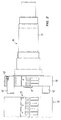
- a cross cutter 11 of which only part of the housing is indicated, and which is a so-called Folio cross cutter is in bearings 12 is a knife shaft 13 stored. It cuts in cooperation with you accordingly, i.e. trained essentially the same Counter knife from one path, from several, from different Upcoming paper roll bearings exist, relatively large Sheets of paper that are subsequently, e.g. in giants or stacks of paper collected on pallets.
- Knife shaft 13 which consists of a multi-stepped pin 15 and a flange 16 integral therewith intervenes Drive 17, to which a synchronous gear 47 belongs, the is rotatably attached to the shaft journal.
- This gear meshes with a corresponding synchronous gearwheel with the shown cutter shaft 13 cooperating cutter shaft.
- synchronous wheels at both ends of a knife shaft intended.
- the drive from the drive motors can either directly on the shaft journal 15 or via the synchronous gear respectively.
- the cutting area 48 of the knife shaft extends to that pin-side end of the flange 16. Up to there forms the Outer periphery 18 of the flange the immediate continuation of the Surface of a knife roller 19, which most of the Occupies the cutting area.
- the knife roller consists of a circular cylindrical section made of an aluminum alloy (see Fig. 3), in the outer circumference opposite to each other Recesses 20 in the manner of approximately longitudinal Grooves for knife holder 21 for attaching the lighter Knife 22 clamped to the axis is provided is. The clamping takes place via a clamping wedge 23, which Knife in the area of its thickening away from the cutting edge Tight foot.
- the clamping wedge 23 is by screws 53 into the trapezoidal ones narrowing in cross section Recesses 20 drawn into it.
- the recess 20 (knife groove) lined with a steel strip 54, which for a uniform Distribution of the contact pressure without plastic deformation worries.
- Knife takes place over a multitude of arranged side by side and approximately tangentially directed adjusting screws 24, in corresponding threaded holes 25 in the knife roller 19 are screwed in.
- the knife carrier recesses 20 and the knife 22 also extend over the outer circumference of the flange 16 away, so that this is an active part of the knife shaft forms.
- the knife attachments, e.g. the clamping wedges 23, additionally act like pass wedges that are described later Support flange / knife roller connection.
- Fig. 3 also shows that the made of solid material Knife roller has a plurality of longitudinal bores all run parallel to the axis of rotation 26 of the cutter shaft 13.
- the socket recesses 27 form. They have a relatively large cross-section, e.g. between 25 and 40% of the knife roller diameter and so are arranged that their axes 28 on the corners of an imaginary Squares. This is arranged so that the knife holder are approximately in the extension of the webs 29, which are form between the socket recesses 27.
- 3 are the recesses 20 somewhat laterally in between each two socket recesses 27 forming solid material gusset 49 shown what results from the oblique course of the knife carrier recess 20 results.
- dowel pin recesses 30 is provided, which is relatively close to the circumference 18 of the Knife roller are provided. They are an extension of the Crosspieces 29 between socket recesses 27, which are at right angles the previously mentioned webs.
- bushing recesses are also relatively close to the circumference 18 reach is an area in the middle of the cross section formed, which occupies a central recess 31 which is coaxial extends to the axis of rotation 26.
- the cross section of the knife roller 19 thus has its solid material sections that have remained between the recesses the shape of a central central recess 31 wheel arranged around it with hub, four spokes (webs 29) and a peripheral, largely closed edge area 32 like a wheel tire.
- the socket recesses are located here 27 regularly distributed around the axis of rotation 26 and compared to smaller dowel pin recesses on the one hand and the recesses 20 for the knife are on the other hand each in the gaps in between, so that there is largely self-balanced and especially with regard to the Main stresses (torsion and bending) stable, on the other hand but in terms of inertia and weight, which in the bend comes in, gives almost ideal structure.
- the invention is the most important part in a cutter shaft forming a cross cutter a principle redundancy reached.
- a material for the knife roller can instead the preferred aluminum alloy every other technically available light metal can be used. Because of the special Connection method between the light metal body of the Knife roller and the shaft end 14 with steel pin 15 and Flange 16 ensures that in particular the aluminum material nowhere too high becomes. So it cannot be plastic or impermissibly large elastic deformations occur.
Landscapes
- Life Sciences & Earth Sciences (AREA)
- Forests & Forestry (AREA)
- Engineering & Computer Science (AREA)
- Mechanical Engineering (AREA)
- Perforating, Stamping-Out Or Severing By Means Other Than Cutting (AREA)
- Details Of Cutting Devices (AREA)
- Crushing And Pulverization Processes (AREA)
- Treatment Of Fiber Materials (AREA)
- Polishing Bodies And Polishing Tools (AREA)
- Shearing Machines (AREA)
- Replacement Of Web Rolls (AREA)
Applications Claiming Priority (2)
| Application Number | Priority Date | Filing Date | Title |
|---|---|---|---|
| DE19848973A DE19848973A1 (de) | 1998-10-23 | 1998-10-23 | Querschneider für Bahnmaterialien |
| DE19848973 | 1998-10-23 |
Publications (3)
| Publication Number | Publication Date |
|---|---|
| EP0995560A2 true EP0995560A2 (fr) | 2000-04-26 |
| EP0995560A3 EP0995560A3 (fr) | 2001-05-16 |
| EP0995560B1 EP0995560B1 (fr) | 2004-05-06 |
Family
ID=7885447
Family Applications (1)
| Application Number | Title | Priority Date | Filing Date |
|---|---|---|---|
| EP99120489A Expired - Lifetime EP0995560B1 (fr) | 1998-10-23 | 1999-10-15 | Machine pour la coupe transversale de matériaux en bande |
Country Status (6)
| Country | Link |
|---|---|
| US (1) | US6308605B1 (fr) |
| EP (1) | EP0995560B1 (fr) |
| JP (1) | JP2000141283A (fr) |
| AT (1) | ATE265916T1 (fr) |
| DE (2) | DE19848973A1 (fr) |
| ES (1) | ES2221288T3 (fr) |
Cited By (2)
| Publication number | Priority date | Publication date | Assignee | Title |
|---|---|---|---|---|
| DE202019101574U1 (de) | 2019-03-20 | 2020-06-30 | Bw Papersystems Hamburg Gmbh | Messertrommel |
| WO2020187647A1 (fr) | 2019-03-20 | 2020-09-24 | Bw Papersystems Hamburg Gmbh | Tambour à lames |
Families Citing this family (3)
| Publication number | Priority date | Publication date | Assignee | Title |
|---|---|---|---|---|
| US20060272159A1 (en) * | 2005-06-03 | 2006-12-07 | Rubin Richard H | Apparatus and method for cutting items and method of forming the same |
| JP5013799B2 (ja) * | 2006-09-27 | 2012-08-29 | 三菱重工印刷紙工機械株式会社 | ナイフシリンダ、ロータリカッタ、及びナイフ取り付け台の取り付け方法 |
| US10857690B2 (en) * | 2018-09-11 | 2020-12-08 | The Procter & Gamble Company | Method and apparatus for adjusting and maintaining a position of a cutting surface of a perforating apparatus |
Family Cites Families (32)
| Publication number | Priority date | Publication date | Assignee | Title |
|---|---|---|---|---|
| US3908499A (en) * | 1973-08-01 | 1975-09-30 | William Dale Reed | Knife retainer |
| US4131047A (en) * | 1977-03-28 | 1978-12-26 | Harris Corporation | Rotary knife mounting |
| CA1072004A (fr) * | 1977-06-17 | 1980-02-19 | Merrill D. Martin | Cisaille rotative |
| US4143568A (en) * | 1977-06-30 | 1979-03-13 | Butler-Automatic, Inc. | Rotary web cutting apparatus |
| DE2741560A1 (de) * | 1977-09-15 | 1979-03-22 | Jagenberg Werke Ag | Messertrommel fuer querschneider |
| US4183271A (en) * | 1978-03-31 | 1980-01-15 | Merrill David Martin | Rotary web shearing machine |
| US4253363A (en) * | 1979-04-25 | 1981-03-03 | Fram Jerry R | Roving cutter with positive ejection cutting head |
| DE2922164A1 (de) * | 1979-05-31 | 1980-12-04 | Will E C H Gmbh & Co | Querschneider zum schneiden von boegen aus papier, karton, o.dgl. |
| DE2923516A1 (de) * | 1979-06-09 | 1980-12-11 | Will E C H Gmbh & Co | Messertrommel fuer querschneider |
| US4280386A (en) * | 1979-12-26 | 1981-07-28 | The Ward Machinery Company | Paperboard slitting apparatus |
| US4594926A (en) * | 1983-10-24 | 1986-06-17 | Didde Graphic Systems Corporation | File hole punch ring apparatus for web fed paper conveying mechanism |
| DE3518922A1 (de) * | 1985-05-25 | 1986-11-27 | Maschinenfabrik Goebel Gmbh, 6100 Darmstadt | Einrichtung zum verschieben von untermessern |
| DE3608111C1 (de) | 1986-03-12 | 1987-10-01 | Bielomatik Leuze & Co | Querschneider fuer Bahnmaterialien |
| DE3718776C1 (de) * | 1987-06-04 | 1988-08-25 | Strecker Valmet | Rotations-Gleichlaufquerschneider |
| US4854204A (en) * | 1988-03-03 | 1989-08-08 | Am International Incorporated | Rotary knife paper trimmer with long life shearing surfaces for trimming thick and shingled paper products |
| DE8900516U1 (de) | 1989-01-18 | 1989-03-09 | BHS-Bayerische Berg-, Hütten- und Salzwerke AG, 8000 München | Messerbalken für einen Querschneider für Warenbahnen, insbesondere Wellpappe |
| SE461726B (sv) * | 1989-02-06 | 1990-03-19 | Rolf Arne Larsson | Anordning foer fasthaallning av knivblad foer skaerning av en pappersbana |
| IT1238239B (it) * | 1990-02-08 | 1993-07-12 | Selco Srl | Mandrino porta lama a disco particolarmente per macchine sezionatrici. |
| DE4106084A1 (de) * | 1991-02-27 | 1992-09-03 | Will E C H Gmbh & Co | Rotationsquerschneider |
| EP0523435B1 (fr) * | 1991-07-04 | 1997-02-19 | KOENIG & BAUER-ALBERT AKTIENGESELLSCHAFT | Coupeuse transversale d'une plieuse pour des rotatives à bobines |
| EP0569767B1 (fr) * | 1992-05-13 | 1996-01-03 | SCHOBER GmbH Werkzeug- und Maschinenbau | Support de couteau |
| DE4223566C2 (de) * | 1992-07-17 | 1995-09-14 | Bielomatik Leuze & Co | Messerwalze für Schneideinrichtungen sowie Verfahren zur wenigstens teilfertigen Herstellung einer Messerwalze |
| DE4229699C2 (de) * | 1992-09-05 | 1995-09-21 | Heidelberger Druckmasch Ag | Vorrichtung zur kontrollierten Beseitigung von Abfall-Stücken von Bedruckstoffen |
| DE4240232C2 (de) * | 1992-11-30 | 1995-04-27 | Bhs Corr Masch & Anlagenbau | Querschneider für Warenbahnen, insbesondere für eine Wellpappenbahn |
| DE4321163C3 (de) * | 1993-06-25 | 2000-07-13 | Freudenberg Carl Fa | Querschneider |
| WO1995028261A1 (fr) * | 1994-04-13 | 1995-10-26 | Winkler & Dünnebier | Emporte-piece souple et cylindre-support |
| DE4417493A1 (de) * | 1994-05-19 | 1995-11-23 | Bielomatik Leuze & Co | Querschneider für Materialbahnen, insbesondere Papier-Formatquerschneider |
| US5464166A (en) * | 1994-08-26 | 1995-11-07 | E. I. Du Pont De Nemours And Company | Method and apparatus for automatic roll transfer |
| US5529450A (en) * | 1995-02-14 | 1996-06-25 | Eastman Kodak Company | Lock nut |
| US5638733A (en) * | 1995-09-01 | 1997-06-17 | Texo S.R.L. | Rotary die cutter unit with rapid die connection |
| DE19545003A1 (de) * | 1995-12-02 | 1997-06-05 | Jagenberg Papiertech Gmbh | Messertrommel für Maschinen zum Querschneiden von Materialbahnen und Verfahren zu ihrer Herstellung |
| DE19632438A1 (de) * | 1996-08-12 | 1998-02-19 | Emtec Magnetics Gmbh | Messer-Zustell-Vorrichtung für Schneide-Anlagen für Bänder, insbesondere Magnetbänder |
-
1998
- 1998-10-23 DE DE19848973A patent/DE19848973A1/de not_active Withdrawn
-
1999
- 1999-10-15 EP EP99120489A patent/EP0995560B1/fr not_active Expired - Lifetime
- 1999-10-15 DE DE59909389T patent/DE59909389D1/de not_active Expired - Lifetime
- 1999-10-15 AT AT99120489T patent/ATE265916T1/de active
- 1999-10-15 JP JP11293727A patent/JP2000141283A/ja active Pending
- 1999-10-15 ES ES99120489T patent/ES2221288T3/es not_active Expired - Lifetime
- 1999-10-22 US US09/425,620 patent/US6308605B1/en not_active Expired - Fee Related
Cited By (3)
| Publication number | Priority date | Publication date | Assignee | Title |
|---|---|---|---|---|
| DE202019101574U1 (de) | 2019-03-20 | 2020-06-30 | Bw Papersystems Hamburg Gmbh | Messertrommel |
| WO2020187647A1 (fr) | 2019-03-20 | 2020-09-24 | Bw Papersystems Hamburg Gmbh | Tambour à lames |
| CN113748003A (zh) * | 2019-03-20 | 2021-12-03 | Bw 纸件系统汉堡有限公司 | 刀辊 |
Also Published As
| Publication number | Publication date |
|---|---|
| EP0995560A3 (fr) | 2001-05-16 |
| ES2221288T3 (es) | 2004-12-16 |
| DE19848973A1 (de) | 2000-04-27 |
| US6308605B1 (en) | 2001-10-30 |
| JP2000141283A (ja) | 2000-05-23 |
| DE59909389D1 (de) | 2004-06-09 |
| ATE265916T1 (de) | 2004-05-15 |
| EP0995560B1 (fr) | 2004-05-06 |
Similar Documents
| Publication | Publication Date | Title |
|---|---|---|
| DE69502550T2 (de) | Profilanpassung für Vielwalzengerüste | |
| EP0295449B1 (fr) | Dispositif pour imprimer ou découper à l'emporte-pièce une bande | |
| DE3303628C2 (fr) | ||
| WO1992016763A1 (fr) | Liaison arbre-moyeu | |
| DE2259143B2 (de) | Walzgerüst zum Walzen von im wesentlichen stangenförmigem Gut | |
| AT514980A1 (de) | Schwenklager und Förderrolle für einen schrägen Einbau derselben in eine Förderanlage | |
| EP0143999A1 (fr) | Unité de tension | |
| EP0995560B1 (fr) | Machine pour la coupe transversale de matériaux en bande | |
| DE3314322C2 (de) | Kreuzgelenk für eine Gelenkwelle | |
| EP0040808B1 (fr) | Cylindre | |
| DE2742442A1 (de) | Kupplung | |
| DE102007009779B4 (de) | Drehverbindung zwischen Welle und Ritzel und Verfahren zu deren Herstellung | |
| DE3142763C2 (de) | Vorrichtung zum Festspannen einer Walzwerkswalze auf einer Trägerwelle | |
| DE10314945A1 (de) | Falzvorrichtung mit Falztrommel | |
| DE3038587C2 (de) | Antreibbare Walze mit steuerbarer Durchbiegung, insbesondere für Maschinen zur Erzeugung und Verarbeitung von Bahnen aus Papier oder Kunststoff | |
| DE1811614C3 (de) | Walzscheibenbefestigung für Draht-, Streckreduzler-Walzwerke und dergleichen Walzwerksmaschinen | |
| EP1374999A2 (fr) | Broyeur à rouleaux | |
| WO1990008272A1 (fr) | Raccord a bride resistant a la torsion | |
| DE69002993T2 (de) | Haupthebel für schnell laufende Drehschaftmaschinen. | |
| DE69216102T2 (de) | Wellpappenmaschine | |
| DE4014424A1 (de) | Rotationsschaelmaschine fuer baumstaemme | |
| DE2439017A1 (de) | Profilwalzmaschine mit hilfsmittel zum auswechseln der profilwalzen | |
| DE10162910A1 (de) | Klemmspaltmutter | |
| DE2812783C2 (de) | Kupplung zum starren Verbinden zweier gleichachsiger Maschinenteile und Verwendung einer solchen Kupplung an einer Gelenkkupplung | |
| EP0924338B1 (fr) | Unité d' entraínement avec support de couple mobil pour rouleaux |
Legal Events
| Date | Code | Title | Description |
|---|---|---|---|
| PUAI | Public reference made under article 153(3) epc to a published international application that has entered the european phase |
Free format text: ORIGINAL CODE: 0009012 |
|
| AK | Designated contracting states |
Kind code of ref document: A2 Designated state(s): AT DE ES GB IT |
|
| AX | Request for extension of the european patent |
Free format text: AL;LT;LV;MK;RO;SI |
|
| PUAL | Search report despatched |
Free format text: ORIGINAL CODE: 0009013 |
|
| AK | Designated contracting states |
Kind code of ref document: A3 Designated state(s): AT BE CH CY DE DK ES FI FR GB GR IE IT LI LU MC NL PT SE |
|
| AX | Request for extension of the european patent |
Free format text: AL;LT;LV;MK;RO;SI |
|
| 17P | Request for examination filed |
Effective date: 20010607 |
|
| AKX | Designation fees paid |
Free format text: AT DE ES GB IT |
|
| 17Q | First examination report despatched |
Effective date: 20030307 |
|
| GRAP | Despatch of communication of intention to grant a patent |
Free format text: ORIGINAL CODE: EPIDOSNIGR1 |
|
| GRAS | Grant fee paid |
Free format text: ORIGINAL CODE: EPIDOSNIGR3 |
|
| GRAA | (expected) grant |
Free format text: ORIGINAL CODE: 0009210 |
|
| AK | Designated contracting states |
Kind code of ref document: B1 Designated state(s): AT DE ES GB IT |
|
| PG25 | Lapsed in a contracting state [announced via postgrant information from national office to epo] |
Ref country code: GB Free format text: LAPSE BECAUSE OF FAILURE TO SUBMIT A TRANSLATION OF THE DESCRIPTION OR TO PAY THE FEE WITHIN THE PRESCRIBED TIME-LIMIT Effective date: 20040506 |
|
| REG | Reference to a national code |
Ref country code: GB Ref legal event code: FG4D Free format text: NOT ENGLISH |
|
| REF | Corresponds to: |
Ref document number: 59909389 Country of ref document: DE Date of ref document: 20040609 Kind code of ref document: P |
|
| GBV | Gb: ep patent (uk) treated as always having been void in accordance with gb section 77(7)/1977 [no translation filed] |
Effective date: 20040506 |
|
| REG | Reference to a national code |
Ref country code: ES Ref legal event code: FG2A Ref document number: 2221288 Country of ref document: ES Kind code of ref document: T3 |
|
| PLBE | No opposition filed within time limit |
Free format text: ORIGINAL CODE: 0009261 |
|
| STAA | Information on the status of an ep patent application or granted ep patent |
Free format text: STATUS: NO OPPOSITION FILED WITHIN TIME LIMIT |
|
| 26N | No opposition filed |
Effective date: 20050208 |
|
| PGFP | Annual fee paid to national office [announced via postgrant information from national office to epo] |
Ref country code: AT Payment date: 20101014 Year of fee payment: 12 |
|
| REG | Reference to a national code |
Ref country code: AT Ref legal event code: MM01 Ref document number: 265916 Country of ref document: AT Kind code of ref document: T Effective date: 20111015 |
|
| PG25 | Lapsed in a contracting state [announced via postgrant information from national office to epo] |
Ref country code: AT Free format text: LAPSE BECAUSE OF NON-PAYMENT OF DUE FEES Effective date: 20111015 |
|
| PGFP | Annual fee paid to national office [announced via postgrant information from national office to epo] |
Ref country code: DE Payment date: 20131021 Year of fee payment: 15 |
|
| PGFP | Annual fee paid to national office [announced via postgrant information from national office to epo] |
Ref country code: ES Payment date: 20131029 Year of fee payment: 15 Ref country code: IT Payment date: 20131023 Year of fee payment: 15 |
|
| REG | Reference to a national code |
Ref country code: DE Ref legal event code: R119 Ref document number: 59909389 Country of ref document: DE |
|
| PG25 | Lapsed in a contracting state [announced via postgrant information from national office to epo] |
Ref country code: DE Free format text: LAPSE BECAUSE OF NON-PAYMENT OF DUE FEES Effective date: 20150501 |
|
| PG25 | Lapsed in a contracting state [announced via postgrant information from national office to epo] |
Ref country code: IT Free format text: LAPSE BECAUSE OF NON-PAYMENT OF DUE FEES Effective date: 20141015 |
|
| REG | Reference to a national code |
Ref country code: ES Ref legal event code: FD2A Effective date: 20151126 |
|
| PG25 | Lapsed in a contracting state [announced via postgrant information from national office to epo] |
Ref country code: ES Free format text: LAPSE BECAUSE OF NON-PAYMENT OF DUE FEES Effective date: 20141016 |