EP0995578A2 - Contrôle d'un actuateur hydraulique pour une machine de moulage par injection - Google Patents
Contrôle d'un actuateur hydraulique pour une machine de moulage par injection Download PDFInfo
- Publication number
- EP0995578A2 EP0995578A2 EP99308128A EP99308128A EP0995578A2 EP 0995578 A2 EP0995578 A2 EP 0995578A2 EP 99308128 A EP99308128 A EP 99308128A EP 99308128 A EP99308128 A EP 99308128A EP 0995578 A2 EP0995578 A2 EP 0995578A2
- Authority
- EP
- European Patent Office
- Prior art keywords
- control
- microcontroller
- actuator
- hydraulic
- valve
- Prior art date
- Legal status (The legal status is an assumption and is not a legal conclusion. Google has not performed a legal analysis and makes no representation as to the accuracy of the status listed.)
- Granted
Links
Images


Classifications
-
- B—PERFORMING OPERATIONS; TRANSPORTING
- B23—MACHINE TOOLS; METAL-WORKING NOT OTHERWISE PROVIDED FOR
- B23K—SOLDERING OR UNSOLDERING; WELDING; CLADDING OR PLATING BY SOLDERING OR WELDING; CUTTING BY APPLYING HEAT LOCALLY, e.g. FLAME CUTTING; WORKING BY LASER BEAM
- B23K3/00—Tools, devices or special appurtenances for soldering, e.g. brazing, or unsoldering, not specially adapted for particular methods
- B23K3/06—Solder feeding devices; Solder melting pans
- B23K3/0607—Solder feeding devices
- B23K3/0623—Solder feeding devices for shaped solder piece feeding, e.g. preforms, bumps, balls, pellets, droplets
-
- B—PERFORMING OPERATIONS; TRANSPORTING
- B29—WORKING OF PLASTICS; WORKING OF SUBSTANCES IN A PLASTIC STATE IN GENERAL
- B29C—SHAPING OR JOINING OF PLASTICS; SHAPING OF MATERIAL IN A PLASTIC STATE, NOT OTHERWISE PROVIDED FOR; AFTER-TREATMENT OF THE SHAPED PRODUCTS, e.g. REPAIRING
- B29C45/00—Injection moulding, i.e. forcing the required volume of moulding material through a nozzle into a closed mould; Apparatus therefor
- B29C45/17—Component parts, details or accessories; Auxiliary operations
- B29C45/76—Measuring, controlling or regulating
- B29C45/82—Hydraulic or pneumatic circuits
-
- B—PERFORMING OPERATIONS; TRANSPORTING
- B29—WORKING OF PLASTICS; WORKING OF SUBSTANCES IN A PLASTIC STATE IN GENERAL
- B29C—SHAPING OR JOINING OF PLASTICS; SHAPING OF MATERIAL IN A PLASTIC STATE, NOT OTHERWISE PROVIDED FOR; AFTER-TREATMENT OF THE SHAPED PRODUCTS, e.g. REPAIRING
- B29C2945/00—Indexing scheme relating to injection moulding, i.e. forcing the required volume of moulding material through a nozzle into a closed mould
- B29C2945/76—Measuring, controlling or regulating
- B29C2945/76003—Measured parameter
- B29C2945/76006—Pressure
-
- B—PERFORMING OPERATIONS; TRANSPORTING
- B29—WORKING OF PLASTICS; WORKING OF SUBSTANCES IN A PLASTIC STATE IN GENERAL
- B29C—SHAPING OR JOINING OF PLASTICS; SHAPING OF MATERIAL IN A PLASTIC STATE, NOT OTHERWISE PROVIDED FOR; AFTER-TREATMENT OF THE SHAPED PRODUCTS, e.g. REPAIRING
- B29C2945/00—Indexing scheme relating to injection moulding, i.e. forcing the required volume of moulding material through a nozzle into a closed mould
- B29C2945/76—Measuring, controlling or regulating
- B29C2945/76003—Measured parameter
- B29C2945/76083—Position
-
- B—PERFORMING OPERATIONS; TRANSPORTING
- B29—WORKING OF PLASTICS; WORKING OF SUBSTANCES IN A PLASTIC STATE IN GENERAL
- B29C—SHAPING OR JOINING OF PLASTICS; SHAPING OF MATERIAL IN A PLASTIC STATE, NOT OTHERWISE PROVIDED FOR; AFTER-TREATMENT OF THE SHAPED PRODUCTS, e.g. REPAIRING
- B29C2945/00—Indexing scheme relating to injection moulding, i.e. forcing the required volume of moulding material through a nozzle into a closed mould
- B29C2945/76—Measuring, controlling or regulating
- B29C2945/76494—Controlled parameter
- B29C2945/76498—Pressure
-
- B—PERFORMING OPERATIONS; TRANSPORTING
- B29—WORKING OF PLASTICS; WORKING OF SUBSTANCES IN A PLASTIC STATE IN GENERAL
- B29C—SHAPING OR JOINING OF PLASTICS; SHAPING OF MATERIAL IN A PLASTIC STATE, NOT OTHERWISE PROVIDED FOR; AFTER-TREATMENT OF THE SHAPED PRODUCTS, e.g. REPAIRING
- B29C2945/00—Indexing scheme relating to injection moulding, i.e. forcing the required volume of moulding material through a nozzle into a closed mould
- B29C2945/76—Measuring, controlling or regulating
- B29C2945/76494—Controlled parameter
- B29C2945/76505—Force
-
- B—PERFORMING OPERATIONS; TRANSPORTING
- B29—WORKING OF PLASTICS; WORKING OF SUBSTANCES IN A PLASTIC STATE IN GENERAL
- B29C—SHAPING OR JOINING OF PLASTICS; SHAPING OF MATERIAL IN A PLASTIC STATE, NOT OTHERWISE PROVIDED FOR; AFTER-TREATMENT OF THE SHAPED PRODUCTS, e.g. REPAIRING
- B29C2945/00—Indexing scheme relating to injection moulding, i.e. forcing the required volume of moulding material through a nozzle into a closed mould
- B29C2945/76—Measuring, controlling or regulating
- B29C2945/76494—Controlled parameter
- B29C2945/76531—Temperature
-
- B—PERFORMING OPERATIONS; TRANSPORTING
- B29—WORKING OF PLASTICS; WORKING OF SUBSTANCES IN A PLASTIC STATE IN GENERAL
- B29C—SHAPING OR JOINING OF PLASTICS; SHAPING OF MATERIAL IN A PLASTIC STATE, NOT OTHERWISE PROVIDED FOR; AFTER-TREATMENT OF THE SHAPED PRODUCTS, e.g. REPAIRING
- B29C2945/00—Indexing scheme relating to injection moulding, i.e. forcing the required volume of moulding material through a nozzle into a closed mould
- B29C2945/76—Measuring, controlling or regulating
- B29C2945/76494—Controlled parameter
- B29C2945/76545—Flow rate
-
- B—PERFORMING OPERATIONS; TRANSPORTING
- B29—WORKING OF PLASTICS; WORKING OF SUBSTANCES IN A PLASTIC STATE IN GENERAL
- B29C—SHAPING OR JOINING OF PLASTICS; SHAPING OF MATERIAL IN A PLASTIC STATE, NOT OTHERWISE PROVIDED FOR; AFTER-TREATMENT OF THE SHAPED PRODUCTS, e.g. REPAIRING
- B29C2945/00—Indexing scheme relating to injection moulding, i.e. forcing the required volume of moulding material through a nozzle into a closed mould
- B29C2945/76—Measuring, controlling or regulating
- B29C2945/76494—Controlled parameter
- B29C2945/76568—Position
-
- B—PERFORMING OPERATIONS; TRANSPORTING
- B29—WORKING OF PLASTICS; WORKING OF SUBSTANCES IN A PLASTIC STATE IN GENERAL
- B29C—SHAPING OR JOINING OF PLASTICS; SHAPING OF MATERIAL IN A PLASTIC STATE, NOT OTHERWISE PROVIDED FOR; AFTER-TREATMENT OF THE SHAPED PRODUCTS, e.g. REPAIRING
- B29C2945/00—Indexing scheme relating to injection moulding, i.e. forcing the required volume of moulding material through a nozzle into a closed mould
- B29C2945/76—Measuring, controlling or regulating
- B29C2945/76494—Controlled parameter
- B29C2945/76595—Velocity
-
- B—PERFORMING OPERATIONS; TRANSPORTING
- B29—WORKING OF PLASTICS; WORKING OF SUBSTANCES IN A PLASTIC STATE IN GENERAL
- B29C—SHAPING OR JOINING OF PLASTICS; SHAPING OF MATERIAL IN A PLASTIC STATE, NOT OTHERWISE PROVIDED FOR; AFTER-TREATMENT OF THE SHAPED PRODUCTS, e.g. REPAIRING
- B29C2945/00—Indexing scheme relating to injection moulding, i.e. forcing the required volume of moulding material through a nozzle into a closed mould
- B29C2945/76—Measuring, controlling or regulating
- B29C2945/76655—Location of control
- B29C2945/76732—Mould
- B29C2945/76752—Mould runners, nozzles
- B29C2945/76759—Mould runners, nozzles manifolds
-
- B—PERFORMING OPERATIONS; TRANSPORTING
- B29—WORKING OF PLASTICS; WORKING OF SUBSTANCES IN A PLASTIC STATE IN GENERAL
- B29C—SHAPING OR JOINING OF PLASTICS; SHAPING OF MATERIAL IN A PLASTIC STATE, NOT OTHERWISE PROVIDED FOR; AFTER-TREATMENT OF THE SHAPED PRODUCTS, e.g. REPAIRING
- B29C2945/00—Indexing scheme relating to injection moulding, i.e. forcing the required volume of moulding material through a nozzle into a closed mould
- B29C2945/76—Measuring, controlling or regulating
- B29C2945/76655—Location of control
- B29C2945/76775—Fluids
- B29C2945/76785—Fluids hydraulic fluids
-
- B—PERFORMING OPERATIONS; TRANSPORTING
- B29—WORKING OF PLASTICS; WORKING OF SUBSTANCES IN A PLASTIC STATE IN GENERAL
- B29C—SHAPING OR JOINING OF PLASTICS; SHAPING OF MATERIAL IN A PLASTIC STATE, NOT OTHERWISE PROVIDED FOR; AFTER-TREATMENT OF THE SHAPED PRODUCTS, e.g. REPAIRING
- B29C2945/00—Indexing scheme relating to injection moulding, i.e. forcing the required volume of moulding material through a nozzle into a closed mould
- B29C2945/76—Measuring, controlling or regulating
- B29C2945/76929—Controlling method
- B29C2945/76936—The operating conditions are corrected in the next phase or cycle
-
- B—PERFORMING OPERATIONS; TRANSPORTING
- B29—WORKING OF PLASTICS; WORKING OF SUBSTANCES IN A PLASTIC STATE IN GENERAL
- B29C—SHAPING OR JOINING OF PLASTICS; SHAPING OF MATERIAL IN A PLASTIC STATE, NOT OTHERWISE PROVIDED FOR; AFTER-TREATMENT OF THE SHAPED PRODUCTS, e.g. REPAIRING
- B29C2945/00—Indexing scheme relating to injection moulding, i.e. forcing the required volume of moulding material through a nozzle into a closed mould
- B29C2945/76—Measuring, controlling or regulating
- B29C2945/76929—Controlling method
- B29C2945/76939—Using stored or historical data sets
-
- B—PERFORMING OPERATIONS; TRANSPORTING
- B29—WORKING OF PLASTICS; WORKING OF SUBSTANCES IN A PLASTIC STATE IN GENERAL
- B29C—SHAPING OR JOINING OF PLASTICS; SHAPING OF MATERIAL IN A PLASTIC STATE, NOT OTHERWISE PROVIDED FOR; AFTER-TREATMENT OF THE SHAPED PRODUCTS, e.g. REPAIRING
- B29C2945/00—Indexing scheme relating to injection moulding, i.e. forcing the required volume of moulding material through a nozzle into a closed mould
- B29C2945/76—Measuring, controlling or regulating
- B29C2945/76929—Controlling method
- B29C2945/76956—Proportional
- B29C2945/76966—Proportional and integral, i.e. Pl regulation
-
- G—PHYSICS
- G05—CONTROLLING; REGULATING
- G05B—CONTROL OR REGULATING SYSTEMS IN GENERAL; FUNCTIONAL ELEMENTS OF SUCH SYSTEMS; MONITORING OR TESTING ARRANGEMENTS FOR SUCH SYSTEMS OR ELEMENTS
- G05B2219/00—Program-control systems
- G05B2219/30—Nc systems
- G05B2219/41—Servomotor, servo controller till figures
- G05B2219/41124—Nonlinear compensation
-
- G—PHYSICS
- G05—CONTROLLING; REGULATING
- G05B—CONTROL OR REGULATING SYSTEMS IN GENERAL; FUNCTIONAL ELEMENTS OF SUCH SYSTEMS; MONITORING OR TESTING ARRANGEMENTS FOR SUCH SYSTEMS OR ELEMENTS
- G05B2219/00—Program-control systems
- G05B2219/30—Nc systems
- G05B2219/41—Servomotor, servo controller till figures
- G05B2219/41309—Hydraulic or pneumatic drive
Definitions
- the present invention relates to an apparatus and methods for controlling a hydraulic actuator for use in an injection molding machine, and more particularly to controlling such a hydraulic actuator (both linear and rotary) with a processor which is disposed locally near the actuator and/or the hydraulic manifold.
- Injection molding machines produce great quantities of products at high speed. For example, the widely-used PET plastic drink containers are made at production rates of thousands per hour.
- various injection molding machine devices (such as the molding clamp assembly, the injectors, various control switches, and other machine components) are moved using a number of hydraulic actuators.
- Such hydraulic actuators are supplied with pressurized hydraulic fluid that causes movement of an internal diaphragm or piston which, in turn, drives the molding device.
- a control valve controls the flow of hydraulic fluid to the actuator to control movement of the diaphragm.
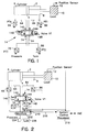
- Figure 1 depicts a typical control valve.
- the hydraulic actuator 2 includes a piston 4 which divides a chamber into two halves 6 and 8. Movement of the piston 4 drives a load 10, which, for example, may comprise a mold and clamp mechanism.
- a position sensor 12 senses the position of the load 10 and provides a feedback signal to a system controller (to be discussed below).
- the hydraulic actuator 2 has two hydraulic fluid lines 64 and 84 which allow hydraulic fluid to enter and escape from the chamber halves 6 and 8, respectively.
- Pressure transducers 66 and 86 respectively monitor the pressure in line 64 and 84 and provide output signals to the system controller.
- Hydraulic fluid from a pressure source (typically a hydraulic fluid pump; not shown in Fig. 1) is provided to valve 14 through hydraulic line 74, while hydraulic fluid may be returned from valve 14 to hydraulic fluid storage tank (also not shown in Fig. 1) through hydraulic line 94.
- Pressure transducers 76 and 96 respectively monitor the pressure in lines 74 and 94 and provide output signals to the system controller.
- Valve 14 controls the flow of hydraulic fluid through the chambers of hydraulic actuator 2 to move the piston 4 back and forth thus driving the load 10.
- Valve 14 has fluid ports A, B, P, and T which are respectively coupled to the hydraulic lines 64, 84, 74, and 94, as shown.
- the valve 14 has a straight flow section 142 and a cross-flow section 144 which are respectively driven by solenoids 146 and 148 in order to control the flow of fluid within the valve. For example, when the straight flow section 142 is driven to the A, B, P, and T ports, pressurized fluid will flow through lines 74 and 64 into chamber 6, driving the piston 4 toward the load 10. On the other hand, if cross-flow section 144 is driven to the ports A, B, P, and T, then pressurized hydraulic fluid will be provided through lines 74 and 84 to the chamber 8, driving the piston 4 away from the load 10.
- the analog signal processor and/or programmable logic controller will receive feedback signals from the pressure transducer units 66, 76, 86, and 96, and position information from position sensor 12 in order to control valve 14 according to a predetermined control program.
- the analog signal processor can also effect operational changes in the operation of the actuator 2 through command signals received through the programmable logic controller, for example to change the molding and clamping times used by load 10.
- the programmable logic controller stores a plurality of predetermined control programs which cause the analog signal processor to control the analog devices of the injection molding machine.
- the programmable logic controller may also include circuitry for controlling the digital devices in the injection molding machine, for example, digital solenoid valves and proximity switches. The programmable logic controller thus controls the elements of the injection molding machine either through the analog signal processor or directly through the digital devices.
- the analog signal processor and the programmable logic controller are required to perform command and control operations for all of the various devices in the machine. This imposes a processing bottleneck.
- the programmable logic controller may attempt to execute closed-loop control of multiple different analog devices at the same time.
- faster and more powerful processors have been used in an attempt to overcome such problems.
- Such expensive solutions have, nevertheless, been unable to solve the control timing problems experienced in known actuator control architectures.
- the dedicated wiring inter-connections used for communication between the analog signal processor and the programmable logic controller to each actuator results in a plurality of wires which are difficult to install, maintain, and repair.
- An object of the present invention is to overcome the problems noted above by providing a local processor disposed near the actuator so that control functions are moved closer to the actuator and away from the central processor.
- a microcontroller is mounted directly on each hydraulic fluid distribution manifold, and this microcontroller controls the actuators coupled to that manifold.
- Each hydraulic actuator can be controlled from a local processor, eliminating the need for a great number of wires between the actuator and the analog signal processor and/or the machine controller, such as a programmable logic controller. This enables modular control sub-systems to be realized. Also, a failure of any manifold-mounted microcontroller will only require its replacement, not the replacement of the central controller or the other manifold microcontrollers.
- an intelligent hydraulic actuator for use in an injection molding machine which also has a system controller includes a hydraulic actuator for moving in a linear or rotary manner between first and second positions ,or for generating forces or torque in response to hydraulic flow and pressure, respectively.
- a microcontroller is disposed adjacent the actuator for causing the actuator to move between the first and second positions.
- the microcontroller is also coupled to the system controller.
- apparatus for controlling a hydraulic actuator in an injection molding machine having (i) a hydraulic manifold for supplying hydraulic fluid to the hydraulic actuator, (ii) a system control processor, and (iii) a sensor for sensing the operational conditions of the hydraulic actuator includes a processor which controls movement of the actuator.
- the processor has a memory for storing at least one control program which the processor runs to control the movement.
- the processor is mounted on the manifold.
- a command input provides command signals from the system control processor to the local processor, and a control output provides control signals from the processor to a hydraulic valve, thus controlling the actuator.
- an injection molding machine includes a plurality of molding devices which perform an injection molding operation, and a system control processor for causing the plurality of molding devices to perform the injection molding operation.
- a plurality of hydraulic actuators are provided for respectively moving the plurality of molding devices, and a plurality of valves respectively provide hydraulic fluid to the hydraulic actuators to move the plurality of molding devices.
- a manifold provides hydraulic fluid to the plurality of valves.
- a processor is disposed adjacent at least one of (i) the manifold, and (ii) at least one of the plurality of valves.
- the processor is coupled to each of the plurality of valves and to the system control processor.
- the processor stores a control program for each of the plurality of hydraulic actuators coupled thereto, and the processor controls the plurality of valves based on the stored control programs and command signals received from the system control processor.
- a method of controlling a hydraulic actuator which is supplied with hydraulic fluid from a controllable valve and a manifold includes the steps of (i) disposing a microcontroller adjacent the manifold, (ii) storing in the microcontroller a control program for controlling a movement of the hydraulic actuator, (iii) providing to the microcontroller feedback signals from a sensor which senses a performance characteristic of the hydraulic actuator, (iv) providing to the microcontroller command signals from the system control processor, (v) calculating, in the microcontroller, control signals to control the valve to cause the movement of the hydraulic controller, the microcontroller being capable of calculating the control signals based on one or more of the feedback signals, the command signals, and the stored control programs, and (vi) transmitting the control signals to the controllable valve.
- apparatus for controlling non-linear characteristics of a hydraulic actuator having a valve and a feedback sensor includes a memory for storing multi-dimensional data regarding operational characteristics of the valve, and a processor.
- the processor receives feedback signals from the feedback sensor, determines operational data from the multi-dimensional data stored in the memory based on the received feedback signals, generates control signals by applying an inverse function to the operational data in order to control for non-linear characteristics of the hydraulic actuator, and outputs the control signals to the valve.
- a further aspect of the present invention involves apparatus for controlling a hydraulic actuator comprising a first valve coupled to the actuator and causing movement of the actuator by controlling movement of hydraulic fluid through the valve, a second valve coupled to both the first valve and the actuator for causing movement of the actuator by controlling movement of hydraulic fluid through the first valve and the second valve, and a microcontroller, disposed adjacent to the valves, for controlling the first valve and the second valve to cause regenerative and non-regenerative control of the actuator.
- An additional aspect of the present invention features at least one computer-readable storage medium storing an instruction set which causes a microcontroller to control a hydraulic actuator and an injection molding machine by performing the steps of: (i) storing a control program which provides control signals based on feedback signals from at least one sensor which monitor operational parameter(s) of the actuator, (ii) receives feedback signals from the sensor(s), (iii) receives command signals from an injection molding system control processor, (iv) modifies the stored control program based on the received command signals, (v) generates actuator control signals based on one of the stored control program and the modified stored program, and (vi) outputs the actuator control signals to the actuator.
- the present invention will be described with respect to controlling hydraulic actuators (both linear and rotary) in an injection molding machine.
- the invention is not limited to injection molding machines and will solve actuator control problems in a wide variety of applications.
- the fluid described below could be any known liquid or gas useful in controlling an actuator.
- the scope of the present invention is to be ascertained from the appended claims and not the detailed description of the preferred embodiments.
- the present invention features a computer, processor, microcontroller, or microcontroller mounted on a hydraulic fluid manifold and/or actuator to provide localized control, enhanced reliability, and reduced wiring in hydraulic actuator control systems.
- Mounting the processor on the manifold and/or actuator thus incorporates the processing and control functionality of a process control unit in an integrated mechanical assembly including hydraulic control valves with digital (on-off switching), proportional and servo functions, and the corresponding valve driver electronics, together with pressure transducers for pressure measurements and linear/rotary transducers for actuator position.
- a closed-loop control system can be realized locally without requiring system control resources.
- the on-board computer possesses communication capability either through the discrete control signals (digital and/or analog) or a field bus which enables networking the local microcontroller to the system control processor and/or other processors disposed within the factory.
- the local microcontroller can be decentralized via fiber optic cable(s), twisted wire pairs, or other communications means.
- the decentralized network capability offered by a field bus improves the control system flexibility.
- Incorporating the computer and communication capabilities of a processor at the local manifold and/or actuator makes it possible to distribute intelligent process control as close as possible to the actuators throughout the system.
- Such manifold-mounted processors having integral field bus connectivity enable control to be decentralized throughout the system.
- the addition of the on-board intellegence (computation) capability of the local microcontroller provides local control of the sub-system. This enables proprietary control techniques and process knowledge to be utilized, yet be open for easy connection to other sub-systems for system integration. Proprietary control techniques such as flow rate linearization (to be discussed below) and dynamic spool cut adaptation (also to be discussed below) can be migrated to the localized on-board computer.
- the on-board computer provides additional diagnostics to the components of the local sub-system, and data acquisition for quality control and monitoring.
- the on-board computer reduces the complexity of the system control processor and enhances the modularity of the system. Now, when problems occur in one local sub-system, it is not necessary to take the whole machine off-line and re-configure the entire control system. Instead, the localmicrocontroller can be replaced and/or reprogrammed to rapidly overcome the sub-system problem and return the machine to full production.
- the preferred embodiment incorporates an on-board microcontroller mounted on a hydraulic manifold which supplies hydraulic fluid to a plurality of valves which, in turn, are coupled to a plurality of hydraulic actuators.
- Communication of control and feedback information between the manifold and the system control processor can be carried out with discrete input and output signals in analog or digital form.
- a standardized industrial fieldbus can also be incorporated to enhance communication with reduced connections. With a single communication point for each sub-system, the overhead to support multiple fieldbus devices is greatly reduced which results in higher response controls from the control system.
- the hydraulic manifold thus becomes an "intelligent" manifold which can perform functions which would not be possible otherwise. Since the processing power demanded from the system control processor is reduced, an overall improvement in system performance and speed is realized.
- the local control of the manifold sub-system thus enables factory calibration and performance characteristic curves for every individual device to be stored in the memory of the on-board microcontroller. This allows additional fine-tuning of the local sub-systems by advanced control strategies and algorithms which, for example, may linearize the feedback from the measurements of the transducers and the control elements. In addition, change of components may be realized by merely revising the data stored in the microcontroller.
- microcontroller This can be done by loading into the microcontroller one or more software programs stored on one or more computer-readable storage mediums such as diskettes, CD-ROMs, tapes, pre-programmed microcontrollers, EEPROMs, optical-magneto devices, etc.
- the programs may be loaded into the microcontroller from the system controller, through a network connection, or directly into the local microcontroller.
- FIG. 2 is a schematic block diagram of one structure according to the preferred embodiment in which the same structure as discussed above with respect to Fig. 1 is depicted with the same reference numerals.
- a hydraulic manifold 202 receives pressurized hydraulic fluid from a pressure source (e.g. a pump, or an accumulator and pump) 204, and returns hydraulic fluid to a tank 206. Hydraulic pressure and return lines extend from the manifold 202 to various valves which operate different hydraulic actuators.
- the manifold 202 provides pressurized and returned hydraulic fluid to the valve 14 discussed above in Fig. 1.
- the microcontroller 210 is in close proximity (e.g. within one meter) to the manifold 202 to control the operations of the valve 14, and thus the actuator 2.
- the microcontroller 210 may also control the other valves and actuators coupled to the manifold 202. While Fig. 2 depicts the microcontroller 210 mounted on the manifold 202, the microcontroller may be mounted adjacent the valve 14 or the actuator 2. So long as the microcontroller is mounted locally, the processing advantages achieved by the present invention can be realized.
- the microcontroller 210 is coupled to the pressure transducers 66, 76, 86, and 96 to monitor the pressure going into and coming out of the valve 14.
- the microcontroller 210 also receives position information from the position sensor 12 coupled to the load 10.
- the microcontroller 210 may also receive feedback signals from other system sensors which monitor various operational characteristics of the hydraulic actuators to be controlled by the microcontroller. Accordingly, the microcontroller 210 can execute closed-loop control of the actuator 2 through control of the valve 14.
- the microcontroller 210 has a ROM (not shown) and a RAM (also not shown) which store one or more control programs which the microcontroller 210 executes to control the solenoid drivers 146, 148 of the valve 14.
- microcontroller 210 contains all necessary programs and receives all necessary feedback, control can be executed without reference to the system control processor 216.
- the microcontroller 210 will provide feedback, status, and operational information to the system controller 216 which, in turn, can command the microcontroller 210 to switch control programs or to modify the programs being executed.
- the new control programs are desired to be installed in the microcontroller 210, these can be installed locally at the manifold, or can be installed through the system control processor 216.
- the microcontroller 210 preferably includes D/A and A/D circuitry so that it can locally control both digital and analog drivers required by the sub-system hydraulic actuators.
- the microcontroller 210 can be any commercially available microcontroller for embedded controls.processor such as a Pentium II processor with one Gigabyte ROM and 64 MB of RAM.
- the microcontroller may also be termed a microprocessor, a computer, a processor, or other terms known to those of skill in the injection molding art. However, the term microcontroller is preferred due to its meaning in this art.
- the system control processor 216 performs overall process control for the injection molding machine and schedules control signals to be supplied to the microcontroller 210. Such signals may include those for calculating the minimum output to a valve based on a velocity profile with a pressure limit.
- the system control processor 216 may receive feedback information from the microcontroller 210 and/or the position sensor 12. This information may include actual pressure, current position, etc.
- the system control processor 216 also receives information from a human machine interface, such as an operator-set velocity profile, pressure limits, temperature set points, etc. Such information is provided to the microcontroller 210 which then decides on the correct outputs to the solenoid valve drivers 146 and 148.
- the control architecture depicted in Fig. 2 provides great flexibility in controlling the injection molding machine. Actuator control functions can reside in the microcontroller 210 and/or the system control processor 216. In a machine with a great number of sub-systems, most of the control functions will be migrated to the individual microcontroller(s) 210. In machines with fewer sub-systems, the system control processor 216 may carry out some of the machine control functions.
- the microcontroller 210 can be installed in a relatively simple system with a single valve, with the microcontroller storing minimal control programs for controlling a single actuator. Or, the microcontroller 210 can be installed as a sophisticated control controlling multiple valves, multiple axes of control, and store control programs for each actuator, as well as control programs for synchronizing the operation of all of the sub-system actuators.
- the microcontroller 210 may store control programs such as: valve displacement vs.
- the microcontroller 210 may, in fact, be standardized for any manifold controlling a simple actuator, such as that depicted in Fig. 2.
- the control program may be identical for different sizes of valves and actuators, and only the initialization parameters (actuator and valve information) need to be input at the start-up period.
- connection between the system control processor 216 and the microcontroller 210 is a fieldbus 218.
- This is a bi-directional bus which may comprise optical cable, a twisted pair, or other suitable communications means.
- the field bus is capable of handling high speed information exchange and can thus provide real-time control between the system control processor 216 and the microcontroller 210.
- the system control processor 216 can send control signals to the microcontroller 210 such as to initiate process signals, scheduling signals, control programs updates, etc.
- the microcontroller 210 can send feedback signals to the system control processor 216 such as valve status, pressure levels, position sensor status, stored reliability information, etc.
- Hydraulic actuators possess non-linear characteristics such as change in hydraulic stiffness due to the change in oil volume between the valve and the cylinder piston and pressure-dependent flow, but the actuator should be operated in the linear region for effective parameter control.
- the non-linear characteristics can lead to loss of control or even closed-loop instability.
- the microcontroller 210 can store a control program which compensates for such non-linear characteristic and ensures linear control of the valve.
- the compensation method according to the present invention will compensate for the main nonlinearity f by an approximate inverse function f -1 , which can be implemented in the controller.
- the regular actuator input U is then substituted by the "corrected" value such that the relationship between U and y becomes approximately linear.
- G A represents the dynamics of the control valve
- G P the mechanical system
- x the process states and variables.
- the dynamics of the valve, G A are often negligible compared with the time constants of G P (control valve versus mechanical system dynamics). If f(x) could offer a precise approximation, good and robust compensation results would be obtained.
- the parameter r provides a means to adjust the flow gain of the valve.
- the flow gain of the valve is limited by the system pressure and maximum area opening of the orifice.
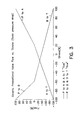
- the following flow characteristic curves help to illustrate the effects of the compensation based on different r values.
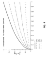
- Figure 4 is a graph depicting the uncompensated flow rate versus demand.
- a single valve controlling an axis has a fixed relationship between the connection of each valve port (i.e. P, T, A, and B), since the spool is one piece.
- the spool cut (the cut of the orifices leading into the chambers) is typically tuned to the ratio of the cylinder (i.e. 2:1, 10:1, etc.). This fixed opening ratio works well for the case of constant velocity, but there is currently no way to adjust the ratio of the valve opening after the system is constructed.
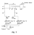
- a solution to this problem is to use two three way (P, T, and A) proportional (servo) valves (Figure 7, valve 72 and valve 74). These valves in conjunction with pressure transducers 66, 76, 86, and 96 in the P, T, and A ports of the valves 72, 74 allow profiling the pressure or flow into and out of the actuator cylinder (this could also be a rotary actuator).
- This system may be used to:
- This embodiment creates an additional degree of freedom for axis control.
- This embodiment can seamlessly adjust the orifice metering in and/or metering out hydraulic fluid (oil) from each side of the cylinder independent of what the other valve is doing.
- the additional degree of control freedom eliminates the requirements of a specially designed spool cut for a single control valve.
- This embodiment also dynamically adjusts the valve openings based on the required flow to the axis and the supply and load pressures. This control is done locally (at the manifold microcontroller) and does not create any processing overhead to the system controller. The complexity of the control algorithm is transparent to the other parts of the system. The combined assembly can be considered as a single valve with an optimum spool cut design for any application.
- An intelligent manifold with embedded microcontroller permits the microcontroller to learn about the system that it is attached to, and to store such characteristic information for more precise control of the actuator.
- Some examples of such stored learning include:
- the local microcontroller may store additional operational parameters to further enhance precision. These parameters may be provided to the system controller for use therein in system wide operational control. For example, the following parameters may be determined by the local microcontroller and stored therein and/or sent to the system controller:
- the following local microcontroller-generated parameters may be stored in the microcontroller and transmitted to the system controller for the operator to use in operation of the injection molding machine:
- Positional restraining force is limited by the capability of the axis 4 0 ⁇ dx dt ⁇ System Limit 0 Velocity Control 5 0 ⁇ F ⁇ System Limit Velocity Control 6 System Limit Velocity Control 7 System Limit 0 Force Control 8 0 ⁇ F ⁇ System Limit Force Control 9 System Limit Force Control
Landscapes
- Engineering & Computer Science (AREA)
- Mechanical Engineering (AREA)
- Manufacturing & Machinery (AREA)
- Injection Moulding Of Plastics Or The Like (AREA)
- Fluid-Pressure Circuits (AREA)
- Servomotors (AREA)
Applications Claiming Priority (2)
| Application Number | Priority Date | Filing Date | Title |
|---|---|---|---|
| US09/173,732 US6289259B1 (en) | 1998-10-16 | 1998-10-16 | Intelligent hydraulic manifold used in an injection molding machine |
| US173732 | 1998-10-16 |
Publications (3)
| Publication Number | Publication Date |
|---|---|
| EP0995578A2 true EP0995578A2 (fr) | 2000-04-26 |
| EP0995578A3 EP0995578A3 (fr) | 2000-09-06 |
| EP0995578B1 EP0995578B1 (fr) | 2006-03-08 |
Family
ID=22633249
Family Applications (1)
| Application Number | Title | Priority Date | Filing Date |
|---|---|---|---|
| EP99308128A Expired - Lifetime EP0995578B1 (fr) | 1998-10-16 | 1999-10-14 | Contrôle d'un actuateur hydraulique pour une machine de moulage par injection |
Country Status (8)
| Country | Link |
|---|---|
| US (2) | US6289259B1 (fr) |
| EP (1) | EP0995578B1 (fr) |
| JP (1) | JP2000120603A (fr) |
| KR (1) | KR100663815B1 (fr) |
| CN (4) | CN1294001C (fr) |
| AT (1) | ATE319550T1 (fr) |
| DE (1) | DE69930218T2 (fr) |
| TW (1) | TW483818B (fr) |
Cited By (4)
| Publication number | Priority date | Publication date | Assignee | Title |
|---|---|---|---|---|
| EP1314533A1 (fr) * | 2001-11-14 | 2003-05-28 | Sumitomo Heavy Industries, Ltd. | Machine à mouler par injection, contenant un accumulateur d'huile hydraulique, et un procédé pour le contrôle de la machine à mouler par injection |
| WO2010027939A3 (fr) * | 2008-09-04 | 2011-05-26 | Dresser, Inc. | Commande de traitement de fluide |
| EP2506097A1 (fr) * | 2011-03-28 | 2012-10-03 | FESTO AG & Co. KG | Système de réglage pour la commande d'un actionneur, procédé de fonctionnement d'un actionneur et produit de programme informatique |
| AT520167A1 (de) * | 2017-07-12 | 2019-01-15 | Engel Austria Gmbh | Hydrauliksystem für eine Formgebungsmaschine |
Families Citing this family (60)
| Publication number | Priority date | Publication date | Assignee | Title |
|---|---|---|---|---|
| US6289259B1 (en) * | 1998-10-16 | 2001-09-11 | Husky Injection Molding Systems Ltd. | Intelligent hydraulic manifold used in an injection molding machine |
| US6377863B1 (en) * | 1999-04-01 | 2002-04-23 | Universal Ventures | Computer-controlled operation of command-input device of automated-production machine |
| US7506328B2 (en) * | 2002-02-11 | 2009-03-17 | Xerox Corporation | Method and system for optimizing performance of an apparatus |
| US6910381B2 (en) * | 2002-05-31 | 2005-06-28 | Mykrolis Corporation | System and method of operation of an embedded system for a digital capacitance diaphragm gauge |
| JP3825737B2 (ja) | 2002-10-24 | 2006-09-27 | 住友重機械工業株式会社 | 精密位置決め装置及びこれを用いた加工機 |
| FR2847116A1 (fr) * | 2002-11-07 | 2004-05-14 | Ksb Sas | Dispositif de commande d'un actionneur electro-hydraulique integre |
| WO2004065798A1 (fr) * | 2003-01-24 | 2004-08-05 | Viking Technologies Lc. | Systeme de positionnement de cylindre hydraulique precis |
| ES2464782T3 (es) * | 2003-02-25 | 2014-06-04 | A.L.M.T. Corp. | Placa metálica refractaria revestida con una capa de superficie de óxido, y soporte de carga para sinterización que la utiliza |
| JP2004293628A (ja) * | 2003-03-26 | 2004-10-21 | Kayaba Ind Co Ltd | 液圧シリンダの制御装置 |
| JP4961211B2 (ja) * | 2003-05-14 | 2012-06-27 | コンティネンタル・テーベス・アクチエンゲゼルシヤフト・ウント・コンパニー・オッフェネ・ハンデルスゲゼルシヤフト | 油圧バルブ用の制御特性曲線を学習する方法 |
| KR100716049B1 (ko) * | 2003-06-11 | 2007-05-08 | 스미도모쥬기가이고교 가부시키가이샤 | 성형기 및 성형방법 |
| US20050236725A1 (en) * | 2004-04-23 | 2005-10-27 | Niewels Joachim J | Method and apparatus for countering mold deflection and misalignment using active material elements |
| US7072735B2 (en) * | 2004-04-23 | 2006-07-04 | Husky Injection Molding Systems Ltd. | Control system for utilizing active material elements in a molding system |
| US20050238757A1 (en) * | 2004-04-23 | 2005-10-27 | Niewels Joachim J | Method and apparatus for assisting ejection from an injection molding machine using active material elements |
| US20050236729A1 (en) * | 2004-04-23 | 2005-10-27 | Arnott Robin A | Method and apparatus for vibrating melt in an injection molding machine using active material elements |
| US20050236727A1 (en) * | 2004-04-23 | 2005-10-27 | Niewels Joachim J | Method and apparatus for mold component locking using active material elements |
| US7293981B2 (en) * | 2004-04-23 | 2007-11-13 | Husky Injection Molding Systems Ltd. | Apparatus for injection molding using active material elements |
| US7481642B2 (en) * | 2004-04-23 | 2009-01-27 | Husky Injection Molding Systems Ltd. | Method and apparatus for controlling a vent gap with active material elements |
| US7165958B2 (en) * | 2004-04-23 | 2007-01-23 | Husky Injection Molding Systems Ltd. | Apparatus for adjustable hot runner assembly seals and tip height using active material elements |
| US7176648B2 (en) * | 2004-05-18 | 2007-02-13 | Husky Injection Molding Systems Ltd. | Energy management apparatus and method for injection molding systems |
| DE102004024907A1 (de) * | 2004-05-19 | 2005-12-15 | Bosch Rexroth Aktiengesellschaft | Maschinensteuerungs- und Regelungssystem für eine Spritzgießmaschine |
| CA2524768C (fr) * | 2005-10-27 | 2012-07-31 | Ipex Inc. | Bague de renfort pour raccord en plastique et raccord en plastique ainsi equipe |
| US7814957B2 (en) * | 2006-07-24 | 2010-10-19 | David A Crown | Door assembly |
| US7707872B2 (en) * | 2006-09-25 | 2010-05-04 | Eaton Corporation | Method for testing a hydraulic manifold |
| US7518523B2 (en) * | 2007-01-05 | 2009-04-14 | Eaton Corporation | System and method for controlling actuator position |
| US7632438B2 (en) * | 2007-05-25 | 2009-12-15 | Husky Injection Molding Systems Ltd. | Intelligent manifold and injection molding machine |
| US20080299244A1 (en) * | 2007-05-29 | 2008-12-04 | Husky Injection Molding Systems Ltd. | Apparatus and Method for Producing Optical Molded Parts |
| CA2762671C (fr) | 2009-06-19 | 2014-07-08 | Husky Injection Molding Systems Ltd. | Commande cinematique dans un systeme hydraulique |
| CN101934578B (zh) * | 2009-06-29 | 2015-07-15 | 鸿富锦精密工业(深圳)有限公司 | 统一各型注塑成型机操作界面的方法及注塑成型系统 |
| KR101170205B1 (ko) | 2010-04-07 | 2012-07-31 | 김지환 | 사출 성형용 금형의 성형물 추출 시험 방법 및 그 장치 |
| US9574952B2 (en) * | 2010-07-12 | 2017-02-21 | Custom Fluid Power Pty Ltd. | Pressure detection device |
| CA2809788A1 (fr) * | 2010-09-13 | 2012-03-22 | Husky Injection Molding Systems Ltd. | Systeme d'outil de moulage avec ensemble actionneur comprenant un ensemble piston et un ensemble membrane souple |
| JP2014511983A (ja) * | 2011-04-12 | 2014-05-19 | ハスキー インジェクション モールディング システムズ リミテッド | 流体ボトルアセンブリと、成形システムと関連付けられた油圧アキュムレータアセンブリとの間の流体圧力の調節のための圧力制御アセンブリを含む装置 |
| CN102338137A (zh) * | 2011-08-25 | 2012-02-01 | 中联重科股份有限公司 | 检测液压阀的方法、控制器和装置、检测液压回路故障的方法和装置以及故障处理系统 |
| CA2865637C (fr) | 2012-02-13 | 2017-03-14 | Husky Injection Molding Systems Ltd. | Flux de fluide hydraulique a partir d'un ensemble accumulateur et d'un ensemble pompe a un actionneur dans le cas ou un plus grand flux est requis |
| US9080319B2 (en) * | 2012-04-17 | 2015-07-14 | Wyoming Machinery Company Inc. | Systems and methods for attachment control signal modulation |
| JP5509256B2 (ja) * | 2012-05-16 | 2014-06-04 | 日精樹脂工業株式会社 | 射出成形装置 |
| US9457853B2 (en) * | 2013-03-14 | 2016-10-04 | Millenworks | Track tensioner |
| DK2811173T4 (da) * | 2013-06-04 | 2022-01-10 | Danfoss Power Solutions Aps | Hydraulisk system og fremgangsmåde til drift af hydraulisk system |
| CN104196777A (zh) * | 2014-09-04 | 2014-12-10 | 燕山大学 | 一种进出口油路独立控制的可编程集成式控制系统 |
| CN104309087B (zh) * | 2014-09-24 | 2017-01-11 | 无锡海天机械有限公司 | 一种具有制动防松结构的注塑机调模机构及调模方法 |
| GB2529909B (en) | 2014-09-30 | 2016-11-23 | Artemis Intelligent Power Ltd | Industrial system with synthetically commutated variable displacement fluid working machine |
| US9484228B2 (en) * | 2014-10-01 | 2016-11-01 | Apple Inc. | Simultaneous independently controlled dual side PCB molding technique |
| TWI610788B (zh) * | 2015-02-04 | 2018-01-11 | 電腦輔助射出成型參數設定系統及方法 | |
| CN104669569B (zh) * | 2015-02-06 | 2017-06-30 | 广州一道注塑机械股份有限公司 | 一种五点机铰合模机构液压系统 |
| CN105599252B (zh) * | 2015-12-30 | 2017-08-22 | 太原理工大学 | 一种注塑机电液混合能量协调回收控制装置 |
| TWI680048B (zh) * | 2016-03-04 | 2019-12-21 | 台達電子工業股份有限公司 | 注塑機控制系統及方法 |
| WO2017210169A1 (fr) * | 2016-06-01 | 2017-12-07 | Synventive Molding Solutions, Inc. | Ensemble dispositif de commande pour un système de moulage par injection |
| WO2017210450A1 (fr) * | 2016-06-01 | 2017-12-07 | Nikon Corporation | Système de commande pour commander un actionneur à fluide |
| CN108507893B (zh) * | 2018-03-28 | 2021-04-27 | 长江大学 | 冲蚀装置以及试样冲蚀磨损速率测量设备 |
| CN109624254B (zh) * | 2019-01-10 | 2021-06-29 | 泰瑞机器股份有限公司 | 一种高响应注塑机伺服泵缸注射系统 |
| TWI695937B (zh) * | 2019-07-22 | 2020-06-11 | 大東原油壓企業有限公司 | 工具機之油壓系統可程式無段壓力控制裝置與其控制之方法 |
| IT201900013278A1 (it) * | 2019-07-30 | 2021-01-30 | Inglass Spa | “Metodo per azionare un attuatore a fluido” |
| JP7632993B2 (ja) | 2019-09-18 | 2025-02-19 | ナブテスコ株式会社 | 電磁比例弁、建設機械 |
| WO2021062523A1 (fr) | 2019-10-04 | 2021-04-08 | Husky Injection Molding Systems Ltd. | Pression de système hydraulique adaptatif stabilisée dans un système de moulage par injection |
| EP3860153B1 (fr) * | 2020-01-31 | 2025-07-02 | Oticon A/s | Prothèse auditive comprenant une bobine d'induction |
| JP7556278B2 (ja) * | 2020-12-08 | 2024-09-26 | Ubeマシナリー株式会社 | ダイカスト鋳造品の品質管理方法 |
| JP7587990B2 (ja) * | 2021-01-14 | 2024-11-21 | 住友重機械工業株式会社 | 制御装置 |
| AT18038U1 (de) * | 2022-04-29 | 2023-11-15 | Engel Austria Gmbh | Hydrauliksystem für eine Formgebungsmaschine |
| CN115324953A (zh) * | 2022-08-09 | 2022-11-11 | 克劳斯玛菲机械(中国)有限公司 | 一种特殊注塑成型工艺中液压缸的液压系统 |
Family Cites Families (32)
| Publication number | Priority date | Publication date | Assignee | Title |
|---|---|---|---|---|
| US4525134A (en) * | 1979-07-20 | 1985-06-25 | American Can Company | Apparatus for making a multi-layer injection blow molded container |
| JPS59189060A (ja) | 1983-04-12 | 1984-10-26 | Ube Ind Ltd | 射出成形装置におけるシリンダ速度制御方法 |
| CA1277115C (fr) | 1986-11-26 | 1990-12-04 | Cincinnati Milacron Inc. | Systeme hydraulique pour machine de type a bascule servant au moulage par injection et apte a donner des reproductions precises |
| JPH01220702A (ja) * | 1988-02-27 | 1989-09-04 | Ishikawajima Harima Heavy Ind Co Ltd | サーボ制御装置 |
| US4971547A (en) * | 1988-05-25 | 1990-11-20 | Signicast Corporation | Apparatus for distributing a fluid substance |
| US5289388A (en) * | 1989-04-21 | 1994-02-22 | Vickers, Incorporated | Electrohydraulic control of a die casting machine |
| US5062052B1 (en) * | 1989-06-20 | 1997-11-18 | Cincinnati Milacron Inc | Logic controlled plastic molding machine with programmable operator interface |
| DE3936301A1 (de) | 1989-11-01 | 1991-05-02 | Kautex Maschinenbau Gmbh | Verfahren zum herstellen von hohlkoerpern aus thermoplastischen kunststoff |
| JPH0471003A (ja) * | 1990-07-12 | 1992-03-05 | Toshiba Corp | プロセス制御装置 |
| JPH04102703A (ja) * | 1990-08-22 | 1992-04-03 | Daikin Ind Ltd | 流体制御装置 |
| JPH0526210A (ja) * | 1991-10-28 | 1993-02-02 | Smc Corp | 分散処理制御装置 |
| DE59309065D1 (de) * | 1993-04-05 | 1998-11-19 | Procontrol Ag | Spritzgiessmaschine mit elektrischem antrieb sowie verfahren zur führung derselben |
| JP2657352B2 (ja) | 1993-09-08 | 1997-09-24 | 日精樹脂工業株式会社 | 射出成形機の圧力検出方法及び装置 |
| US5606513A (en) * | 1993-09-20 | 1997-02-25 | Rosemount Inc. | Transmitter having input for receiving a process variable from a remote sensor |
| US5641523A (en) | 1994-07-20 | 1997-06-24 | Nissei Plastic Industrial Co., Ltd. | Protecting device of an injection molding machine |
| JPH08129401A (ja) * | 1994-11-02 | 1996-05-21 | Yokogawa Electric Corp | バックアップ手段付き駆動装置 |
| US5753153A (en) * | 1996-01-02 | 1998-05-19 | Husky Injection Molding Systems Ltd. | Method for mold clamping units |
| DE69626447D1 (de) * | 1995-06-19 | 2003-04-10 | Siebolt Hettinga | Niederdruckverfahren zum Spritzgiessen eines Kunststoffgegestandes |
| CN1097722C (zh) * | 1995-07-17 | 2003-01-01 | 罗斯蒙德公司 | 用简化过程提供表示经差压发生器的流量信号的变送器 |
| JPH09136149A (ja) * | 1995-11-09 | 1997-05-27 | Nkk Corp | 連続鋳造機モールド内湯面レベル制御方法および装置 |
| US6007236A (en) * | 1995-12-11 | 1999-12-28 | Maguire; Stephen B. | Weigh scale blender and method |
| DE19620360C2 (de) * | 1996-05-13 | 2001-10-04 | Mannesmann Ag | Verfahren und Vorrichtung zum Betreiben einer Spritzgießmaschine |
| US5916605A (en) * | 1996-09-27 | 1999-06-29 | Dynisco Hotrunners, Inc. | Valve actuated injection molding apparatus |
| JP3096895B2 (ja) | 1996-10-09 | 2000-10-10 | 日精樹脂工業株式会社 | 射出成形機の制御方法 |
| JPH10193423A (ja) * | 1997-01-14 | 1998-07-28 | Meiki Co Ltd | アクチュエータの位置と速度の検出装置 |
| US6056536A (en) * | 1997-03-20 | 2000-05-02 | Husky Injection Molding Systems Ltd. | Valve gating apparatus for injection molding |
| JP3172830B2 (ja) * | 1997-03-28 | 2001-06-04 | 日精樹脂工業株式会社 | 射出成形機のアキュムレータ制御方法 |
| US6120277A (en) * | 1997-07-28 | 2000-09-19 | Cincinnatti Milacron Inc. | Hybrid injection molding machine |
| US6089534A (en) * | 1998-01-08 | 2000-07-18 | Xerox Corporation | Fast variable flow microelectromechanical valves |
| US6089849A (en) * | 1998-02-27 | 2000-07-18 | Van Dorn Demag Corporation | Hybrid injection molding machine |
| US6289259B1 (en) * | 1998-10-16 | 2001-09-11 | Husky Injection Molding Systems Ltd. | Intelligent hydraulic manifold used in an injection molding machine |
| US6484107B1 (en) * | 1999-09-28 | 2002-11-19 | Rosemount Inc. | Selectable on-off logic modes for a sensor module |
-
1998
- 1998-10-16 US US09/173,732 patent/US6289259B1/en not_active Expired - Lifetime
-
1999
- 1999-10-12 TW TW088117573A patent/TW483818B/zh not_active IP Right Cessation
- 1999-10-14 JP JP11292977A patent/JP2000120603A/ja active Pending
- 1999-10-14 AT AT99308128T patent/ATE319550T1/de active
- 1999-10-14 KR KR1019990044493A patent/KR100663815B1/ko not_active Expired - Fee Related
- 1999-10-14 DE DE69930218T patent/DE69930218T2/de not_active Expired - Lifetime
- 1999-10-14 EP EP99308128A patent/EP0995578B1/fr not_active Expired - Lifetime
- 1999-10-15 CN CNB021596433A patent/CN1294001C/zh not_active Expired - Fee Related
- 1999-10-15 CN CNB021596425A patent/CN1301845C/zh not_active Expired - Fee Related
- 1999-10-15 CN CNB021596417A patent/CN1282537C/zh not_active Expired - Fee Related
- 1999-10-15 CN CN99121930A patent/CN1101307C/zh not_active Expired - Fee Related
-
2001
- 2001-07-23 US US09/909,958 patent/US6868305B2/en not_active Expired - Lifetime
Cited By (9)
| Publication number | Priority date | Publication date | Assignee | Title |
|---|---|---|---|---|
| EP1314533A1 (fr) * | 2001-11-14 | 2003-05-28 | Sumitomo Heavy Industries, Ltd. | Machine à mouler par injection, contenant un accumulateur d'huile hydraulique, et un procédé pour le contrôle de la machine à mouler par injection |
| SG108880A1 (en) * | 2001-11-14 | 2005-02-28 | Sumitomo Heavy Industries | An injection molding machine having an accumulator and a control method for the injection molding machine |
| US7067078B2 (en) | 2001-11-14 | 2006-06-27 | Sumito Heavy Industries, Ltd. | Injection molding machine having an accumulator and a control method for the injection molding machine |
| WO2010027939A3 (fr) * | 2008-09-04 | 2011-05-26 | Dresser, Inc. | Commande de traitement de fluide |
| US8655494B2 (en) | 2008-09-04 | 2014-02-18 | Dresser, Inc. | Fluid process control |
| EP2506097A1 (fr) * | 2011-03-28 | 2012-10-03 | FESTO AG & Co. KG | Système de réglage pour la commande d'un actionneur, procédé de fonctionnement d'un actionneur et produit de programme informatique |
| AT520167A1 (de) * | 2017-07-12 | 2019-01-15 | Engel Austria Gmbh | Hydrauliksystem für eine Formgebungsmaschine |
| DE102018116234A1 (de) | 2017-07-12 | 2019-01-17 | Engel Austria Gmbh | Hydrauliksystem für eine Formgebungsmaschine |
| AT520167B1 (de) * | 2017-07-12 | 2019-05-15 | Engel Austria Gmbh | Hydrauliksystem für eine Formgebungsmaschine |
Also Published As
| Publication number | Publication date |
|---|---|
| DE69930218T2 (de) | 2006-12-28 |
| KR100663815B1 (ko) | 2007-01-03 |
| DE69930218D1 (de) | 2006-05-04 |
| ATE319550T1 (de) | 2006-03-15 |
| KR20000029068A (ko) | 2000-05-25 |
| CN1259427A (zh) | 2000-07-12 |
| US6868305B2 (en) | 2005-03-15 |
| CN1515401A (zh) | 2004-07-28 |
| EP0995578A3 (fr) | 2000-09-06 |
| EP0995578B1 (fr) | 2006-03-08 |
| CN1515400A (zh) | 2004-07-28 |
| CN1515399A (zh) | 2004-07-28 |
| CN1294001C (zh) | 2007-01-10 |
| US20020013642A1 (en) | 2002-01-31 |
| CN1101307C (zh) | 2003-02-12 |
| JP2000120603A (ja) | 2000-04-25 |
| TW483818B (en) | 2002-04-21 |
| CN1301845C (zh) | 2007-02-28 |
| US6289259B1 (en) | 2001-09-11 |
| CN1282537C (zh) | 2006-11-01 |
Similar Documents
| Publication | Publication Date | Title |
|---|---|---|
| US6289259B1 (en) | Intelligent hydraulic manifold used in an injection molding machine | |
| US8594852B2 (en) | Device and method for controlling a fluid actuator | |
| EP3254998B1 (fr) | Commande d'un système à vide comprenant un générateur de vide | |
| US20200306966A1 (en) | Trajectory planning unit, valve arrangement and method | |
| CN112997012B (zh) | 运动装置、轮胎操纵装置和用于运行流体的致动器的方法 | |
| US7210291B2 (en) | Priority communication protocol for a distributed electrohydraulic system having multiple controllers | |
| US10968927B2 (en) | Hydraulic valve assembly with automated tuning | |
| CN113646709A (zh) | 静液压工作设备及其控制方法 | |
| US20240227269A9 (en) | Hydraulic device and method for regulating a hydraulic device | |
| EP1943180B1 (fr) | Unité de commande et appareil de tête de remplissage | |
| KR100489368B1 (ko) | 가압유체장치 | |
| US20230347565A1 (en) | Hydraulic system for a molding machine | |
| US20060162327A1 (en) | Regulating device for a hydraulic system | |
| US20230367276A1 (en) | Injection molding apparatus | |
| TW202229734A (zh) | 操作液壓驅動器的方法 | |
| Au | Trends in hydraulic positioning systems | |
| JPH0366522B2 (fr) | ||
| JPH10288203A (ja) | 油圧駆動系の制御方式 | |
| JPH08332658A (ja) | 射出成形機の制御方法及び装置 |
Legal Events
| Date | Code | Title | Description |
|---|---|---|---|
| PUAI | Public reference made under article 153(3) epc to a published international application that has entered the european phase |
Free format text: ORIGINAL CODE: 0009012 |
|
| AK | Designated contracting states |
Kind code of ref document: A2 Designated state(s): AT BE CH CY DE DK ES FI FR GB GR IE IT LI LU MC NL PT SE |
|
| AX | Request for extension of the european patent |
Free format text: AL;LT;LV;MK;RO;SI |
|
| PUAL | Search report despatched |
Free format text: ORIGINAL CODE: 0009013 |
|
| AK | Designated contracting states |
Kind code of ref document: A3 Designated state(s): AT BE CH CY DE DK ES FI FR GB GR IE IT LI LU MC NL PT SE |
|
| AX | Request for extension of the european patent |
Free format text: AL;LT;LV;MK;RO;SI |
|
| 17P | Request for examination filed |
Effective date: 20001023 |
|
| AKX | Designation fees paid |
Free format text: AT BE CH CY DE DK ES FI FR GB GR IE IT LI LU MC NL PT SE |
|
| 17Q | First examination report despatched |
Effective date: 20040120 |
|
| GRAP | Despatch of communication of intention to grant a patent |
Free format text: ORIGINAL CODE: EPIDOSNIGR1 |
|
| GRAS | Grant fee paid |
Free format text: ORIGINAL CODE: EPIDOSNIGR3 |
|
| GRAA | (expected) grant |
Free format text: ORIGINAL CODE: 0009210 |
|
| AK | Designated contracting states |
Kind code of ref document: B1 Designated state(s): AT BE CH CY DE DK ES FI FR GB GR IE IT LI LU MC NL PT SE |
|
| PG25 | Lapsed in a contracting state [announced via postgrant information from national office to epo] |
Ref country code: NL Free format text: LAPSE BECAUSE OF FAILURE TO SUBMIT A TRANSLATION OF THE DESCRIPTION OR TO PAY THE FEE WITHIN THE PRESCRIBED TIME-LIMIT Effective date: 20060308 Ref country code: IT Free format text: LAPSE BECAUSE OF FAILURE TO SUBMIT A TRANSLATION OF THE DESCRIPTION OR TO PAY THE FEE WITHIN THE PRESCRIBED TIME-LIMIT;WARNING: LAPSES OF ITALIAN PATENTS WITH EFFECTIVE DATE BEFORE 2007 MAY HAVE OCCURRED AT ANY TIME BEFORE 2007. THE CORRECT EFFECTIVE DATE MAY BE DIFFERENT FROM THE ONE RECORDED. Effective date: 20060308 Ref country code: FI Free format text: LAPSE BECAUSE OF FAILURE TO SUBMIT A TRANSLATION OF THE DESCRIPTION OR TO PAY THE FEE WITHIN THE PRESCRIBED TIME-LIMIT Effective date: 20060308 Ref country code: BE Free format text: LAPSE BECAUSE OF FAILURE TO SUBMIT A TRANSLATION OF THE DESCRIPTION OR TO PAY THE FEE WITHIN THE PRESCRIBED TIME-LIMIT Effective date: 20060308 |
|
| REG | Reference to a national code |
Ref country code: GB Ref legal event code: FG4D |
|
| REG | Reference to a national code |
Ref country code: CH Ref legal event code: EP |
|
| REG | Reference to a national code |
Ref country code: IE Ref legal event code: FG4D |
|
| REG | Reference to a national code |
Ref country code: CH Ref legal event code: NV Representative=s name: BOVARD AG PATENTANWAELTE |
|
| REF | Corresponds to: |
Ref document number: 69930218 Country of ref document: DE Date of ref document: 20060504 Kind code of ref document: P |
|
| PG25 | Lapsed in a contracting state [announced via postgrant information from national office to epo] |
Ref country code: SE Free format text: LAPSE BECAUSE OF FAILURE TO SUBMIT A TRANSLATION OF THE DESCRIPTION OR TO PAY THE FEE WITHIN THE PRESCRIBED TIME-LIMIT Effective date: 20060608 Ref country code: DK Free format text: LAPSE BECAUSE OF FAILURE TO SUBMIT A TRANSLATION OF THE DESCRIPTION OR TO PAY THE FEE WITHIN THE PRESCRIBED TIME-LIMIT Effective date: 20060608 |
|
| PG25 | Lapsed in a contracting state [announced via postgrant information from national office to epo] |
Ref country code: ES Free format text: LAPSE BECAUSE OF FAILURE TO SUBMIT A TRANSLATION OF THE DESCRIPTION OR TO PAY THE FEE WITHIN THE PRESCRIBED TIME-LIMIT Effective date: 20060619 |
|
| PG25 | Lapsed in a contracting state [announced via postgrant information from national office to epo] |
Ref country code: PT Free format text: LAPSE BECAUSE OF FAILURE TO SUBMIT A TRANSLATION OF THE DESCRIPTION OR TO PAY THE FEE WITHIN THE PRESCRIBED TIME-LIMIT Effective date: 20060808 |
|
| NLV1 | Nl: lapsed or annulled due to failure to fulfill the requirements of art. 29p and 29m of the patents act | ||
| PG25 | Lapsed in a contracting state [announced via postgrant information from national office to epo] |
Ref country code: IE Free format text: LAPSE BECAUSE OF NON-PAYMENT OF DUE FEES Effective date: 20061016 |
|
| PG25 | Lapsed in a contracting state [announced via postgrant information from national office to epo] |
Ref country code: MC Free format text: LAPSE BECAUSE OF NON-PAYMENT OF DUE FEES Effective date: 20061031 |
|
| ET | Fr: translation filed | ||
| PLBE | No opposition filed within time limit |
Free format text: ORIGINAL CODE: 0009261 |
|
| STAA | Information on the status of an ep patent application or granted ep patent |
Free format text: STATUS: NO OPPOSITION FILED WITHIN TIME LIMIT |
|
| 26N | No opposition filed |
Effective date: 20061211 |
|
| PG25 | Lapsed in a contracting state [announced via postgrant information from national office to epo] |
Ref country code: GR Free format text: LAPSE BECAUSE OF FAILURE TO SUBMIT A TRANSLATION OF THE DESCRIPTION OR TO PAY THE FEE WITHIN THE PRESCRIBED TIME-LIMIT Effective date: 20060609 |
|
| PG25 | Lapsed in a contracting state [announced via postgrant information from national office to epo] |
Ref country code: CY Free format text: LAPSE BECAUSE OF FAILURE TO SUBMIT A TRANSLATION OF THE DESCRIPTION OR TO PAY THE FEE WITHIN THE PRESCRIBED TIME-LIMIT Effective date: 20060308 |
|
| REG | Reference to a national code |
Ref country code: CH Ref legal event code: PFA Owner name: HUSKY INJECTION MOLDING SYSTEMS LTD. Free format text: HUSKY INJECTION MOLDING SYSTEMS LTD.#500 QUEEN STREET SOUTH#BOLTON ONTARIO L7E 5S5 (CA) -TRANSFER TO- HUSKY INJECTION MOLDING SYSTEMS LTD.#500 QUEEN STREET SOUTH#BOLTON ONTARIO L7E 5S5 (CA) |
|
| REG | Reference to a national code |
Ref country code: DE Ref legal event code: R082 Ref document number: 69930218 Country of ref document: DE Representative=s name: PATRONUS IP PATENT- & RECHTSANWAELTE BERNHARD , DE Ref country code: DE Ref legal event code: R082 Ref document number: 69930218 Country of ref document: DE Representative=s name: CORINNA VOSSIUS IP GROUP PATENT- UND RECHTSANW, DE |
|
| REG | Reference to a national code |
Ref country code: DE Ref legal event code: R082 Ref document number: 69930218 Country of ref document: DE Representative=s name: CORINNA VOSSIUS IP GROUP PATENT- UND RECHTSANW, DE Ref country code: DE Ref legal event code: R082 Ref document number: 69930218 Country of ref document: DE Representative=s name: PATRONUS IP PATENT- & RECHTSANWAELTE BERNHARD , DE |
|
| REG | Reference to a national code |
Ref country code: DE Ref legal event code: R082 Ref document number: 69930218 Country of ref document: DE Representative=s name: CORINNA VOSSIUS IP GROUP PATENT- UND RECHTSANW, DE |
|
| PGFP | Annual fee paid to national office [announced via postgrant information from national office to epo] |
Ref country code: LU Payment date: 20130927 Year of fee payment: 15 |
|
| PGFP | Annual fee paid to national office [announced via postgrant information from national office to epo] |
Ref country code: GB Payment date: 20130927 Year of fee payment: 15 |
|
| PGFP | Annual fee paid to national office [announced via postgrant information from national office to epo] |
Ref country code: FR Payment date: 20130926 Year of fee payment: 15 |
|
| PG25 | Lapsed in a contracting state [announced via postgrant information from national office to epo] |
Ref country code: LU Free format text: LAPSE BECAUSE OF NON-PAYMENT OF DUE FEES Effective date: 20141014 |
|
| GBPC | Gb: european patent ceased through non-payment of renewal fee |
Effective date: 20141014 |
|
| PG25 | Lapsed in a contracting state [announced via postgrant information from national office to epo] |
Ref country code: GB Free format text: LAPSE BECAUSE OF NON-PAYMENT OF DUE FEES Effective date: 20141014 |
|
| REG | Reference to a national code |
Ref country code: FR Ref legal event code: ST Effective date: 20150630 |
|
| PG25 | Lapsed in a contracting state [announced via postgrant information from national office to epo] |
Ref country code: FR Free format text: LAPSE BECAUSE OF NON-PAYMENT OF DUE FEES Effective date: 20141031 |
|
| PGFP | Annual fee paid to national office [announced via postgrant information from national office to epo] |
Ref country code: CH Payment date: 20161004 Year of fee payment: 18 Ref country code: DE Payment date: 20160930 Year of fee payment: 18 |
|
| PGFP | Annual fee paid to national office [announced via postgrant information from national office to epo] |
Ref country code: AT Payment date: 20160930 Year of fee payment: 18 Ref country code: IT Payment date: 20161004 Year of fee payment: 18 |
|
| REG | Reference to a national code |
Ref country code: DE Ref legal event code: R119 Ref document number: 69930218 Country of ref document: DE |
|
| REG | Reference to a national code |
Ref country code: CH Ref legal event code: PL |
|
| REG | Reference to a national code |
Ref country code: AT Ref legal event code: MM01 Ref document number: 319550 Country of ref document: AT Kind code of ref document: T Effective date: 20171014 |
|
| PG25 | Lapsed in a contracting state [announced via postgrant information from national office to epo] |
Ref country code: CH Free format text: LAPSE BECAUSE OF NON-PAYMENT OF DUE FEES Effective date: 20171031 Ref country code: LI Free format text: LAPSE BECAUSE OF NON-PAYMENT OF DUE FEES Effective date: 20171031 Ref country code: DE Free format text: LAPSE BECAUSE OF NON-PAYMENT OF DUE FEES Effective date: 20180501 |
|
| PG25 | Lapsed in a contracting state [announced via postgrant information from national office to epo] |
Ref country code: AT Free format text: LAPSE BECAUSE OF NON-PAYMENT OF DUE FEES Effective date: 20171014 |
|
| PG25 | Lapsed in a contracting state [announced via postgrant information from national office to epo] |
Ref country code: IT Free format text: LAPSE BECAUSE OF NON-PAYMENT OF DUE FEES Effective date: 20171014 |