EP0995663A2 - Chariot de manutention avec un dispositif de direction - Google Patents
Chariot de manutention avec un dispositif de direction Download PDFInfo
- Publication number
- EP0995663A2 EP0995663A2 EP99120323A EP99120323A EP0995663A2 EP 0995663 A2 EP0995663 A2 EP 0995663A2 EP 99120323 A EP99120323 A EP 99120323A EP 99120323 A EP99120323 A EP 99120323A EP 0995663 A2 EP0995663 A2 EP 0995663A2
- Authority
- EP
- European Patent Office
- Prior art keywords
- steering wheel
- industrial truck
- truck according
- steering
- driver
- Prior art date
- Legal status (The legal status is an assumption and is not a legal conclusion. Google has not performed a legal analysis and makes no representation as to the accuracy of the status listed.)
- Withdrawn
Links
- 230000002349 favourable effect Effects 0.000 description 4
- 238000002485 combustion reaction Methods 0.000 description 1
- 238000010276 construction Methods 0.000 description 1
- 238000004519 manufacturing process Methods 0.000 description 1
Images


Classifications
-
- B—PERFORMING OPERATIONS; TRANSPORTING
- B66—HOISTING; LIFTING; HAULING
- B66F—HOISTING, LIFTING, HAULING OR PUSHING, NOT OTHERWISE PROVIDED FOR, e.g. DEVICES WHICH APPLY A LIFTING OR PUSHING FORCE DIRECTLY TO THE SURFACE OF A LOAD
- B66F9/00—Devices for lifting or lowering bulky or heavy goods for loading or unloading purposes
- B66F9/06—Devices for lifting or lowering bulky or heavy goods for loading or unloading purposes movable, with their loads, on wheels or the like, e.g. fork-lift trucks
- B66F9/075—Constructional features or details
- B66F9/07568—Steering arrangements
-
- B—PERFORMING OPERATIONS; TRANSPORTING
- B62—LAND VEHICLES FOR TRAVELLING OTHERWISE THAN ON RAILS
- B62D—MOTOR VEHICLES; TRAILERS
- B62D1/00—Steering controls, i.e. means for initiating a change of direction of the vehicle
- B62D1/02—Steering controls, i.e. means for initiating a change of direction of the vehicle vehicle-mounted
- B62D1/16—Steering columns
- B62D1/18—Steering columns yieldable or adjustable, e.g. tiltable
Definitions
- the invention relates to an industrial truck with a steering device, wherein a steering wheel is arranged adjustable in height by means of a movable fastening device.
- the invention also relates to an industrial truck with a steering device and a rotatable, e.g. driver's seat attached to a substantially vertical column.
- the various controls in one for the driver arrange favorable position.
- the steering wheel on which the driver must access practically during the entire working time should always be in the for the respective driver and the respective work situation are optimally positioned. For this reason, it is known to adjust the height of the steering wheel of an industrial truck to execute.
- the arrangement of the steering wheel on industrial trucks is particularly difficult with a rotating driver's seat.
- Solutions are known in which the steering wheel is arranged in the driver's cab.
- the steering wheel is also known swing with the driver's seat.
- An individual adjustability of the position of the Steering wheel relative to the driver's seat is usually not provided in these solutions.
- the present invention has for its object to provide an industrial truck with a Steering device to provide an ergonomic cheap
- the position of the steering wheel can be adjusted in as many operating situations as possible.
- This task is related to the truck with height-adjustable steering wheel solved in that the fastening device is designed such that a Tilt angle of the steering wheel relative to the horizontal during a height adjustment of the steering wheel remains at least approximately unchanged.
- the angle of inclination The steering wheel thus remains constant and can already be used in the manufacture of the Truck can be optimally adjusted.
- a particularly favorable embodiment is that the fastening device has a parallelogram or linear guide. With a height adjustment of the steering wheel, the parallelogram guidance is shifted.
- a Linear guide can be used, for example, as a dovetail guide or as a linear bearing be executed.
- the fastening device has a means for locking the height adjustment of the Steering wheel on. An unintentional adjustment of the height of the steering wheel is therefore impossible.
- a hydraulic steering valve is provided with particular advantage, which together is height-adjustable with the steering wheel on the fastening device.
- the steering valve is connected directly to a steering shaft of the steering wheel.
- As a connection between the steering valve and a truck frame of the industrial truck only flexible hydraulic and electrical lines are provided.
- the weight force counteracts the steering wheel.
- the force of the gas spring is designed so that it Weight of the steering wheel and the associated components compensated. A Height adjustment of the steering wheel is thus by the operator with little effort possible.
- the fastening device a substantially vertically arranged column
- the steering wheel is pivotally arranged about the vertical column.
- Height adjustment allows the steering wheel to move horizontally around the vertical column Be pivoted towards.
- the steering wheel is shared with the parallelogram guide or linear guide pivoted around the vertical column.
- a particularly favorable arrangement is that a driver's seat rotates around the same vertical column is arranged.
- the object set is also achieved in that the fastening device has two levers spaced apart from one another in the vertical direction, which each with one end on a non-vertically movable part of the steering device are articulated and each connected to the steering wheel at the other end Component is articulated, the levers having a different length.
- the steering wheel becomes automatic when the height is adjusted inclined.
- the respective angle of inclination is due to the lengths of the different ones Lever defined.
- the lower lever is advantageously longer than the upper lever. This measure causes the steering wheel toward the driver during a lifting of the steering wheel is inclined.
- levers are parallel to the middle body plane of a driver are aligned. With this arrangement there is no inclination of the steering wheel from the point of view of the driver in a lateral direction.
- body mean level When defining the body mean level, from a normal sitting position of the driver in the driver's seat.
- the task is related to the industrial truck mentioned at the beginning rotatable driver's seat solved in that the steering wheel by means of a connecting element is attached to the vertical column, with the steering device around the vertical Column is rotatable. So the driver’s seat and steering wheel are attached to the same vertical column, which in turn is rotatably mounted on a vehicle frame of the industrial truck is.
- the steering wheel can be turned around the vertical column independently of the driver’s seat, the steering wheel can be pivoted in the horizontal direction relative to the driver's seat.
- the vertical column can be locked in a rotationally fixed manner relative to the driver's seat. If the lock is actuated, the steering wheel also moves when the driver's seat is turned this with. The position of the steering wheel relative to the driver's seat is therefore not changed.
- the connecting element at least one pipe. So this tube connects the steering wheel with the vertical column.
- Hydraulic and / or electrical lines are advantageously in the tube Steering device arranged.
- the lines are thus protected inside of the tube and continue inside the column to the vehicle frame of the Industrial truck.
- the steering device directly or indirectly connected to the driver's seat and that for recording of hydraulic and / or electrical lines of the steering device a more flexible Hose is provided.
- the steering device is by a Seat attached component worn.
- the flexible hydraulic and electrical lines which are guided into the area of the steering wheel by a frame of the industrial truck are in a flexible hose.
- the flexible hose adapts to the changed geometric conditions Driver's seat on the truck.
- Compared to an arrangement of the lines in a rigid tube enables a larger angle of rotation of the driver's seat.
- a particularly simple construction results when the steering device is directly or is indirectly attached to a seat plate of the driver's seat.
- the bottom of the seat plate is connected to a rotating column.
- the flexible hose connects the steering device to this column.
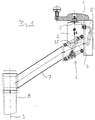
- Figure 1 shows an inventive steering device of an industrial truck a steering wheel 1, which is placed directly on a hydraulic steering valve 2.
- a Rotary movement of the steering wheel 1 is on the steering valve 2 via a short steering shaft 3rd transfer.
- the steering valve 2 is attached to a connecting plate 4, of which Steering valve 2 outgoing hydraulic lines 5 via the connecting plate 4 after are led outside.
- the connection plate is further with a parallelogram guide 6 connected, which at the other end to a connecting element designed as a tube 7 is attached.
- the connecting element 7 is in turn on a vertical Fixed column 8, the connecting element 7 relative to the column 8 around the latter Vertical axis 9 is rotatable and can be locked if necessary.
- the column 8 can also move around a frame of the industrial truck the vertical axis 9 can be rotated.
- a gas spring 35 which is the weight force, is arranged within the parallelogram guide of the steering valve 2 and the components connected thereto.
- the force of the gas spring is essentially adjusted so that its vertical Force component corresponds to the weight G. For height adjustment of the steering wheel only a small force is therefore required.
- the parallelogram 6 is enlarged in the view of FIG. 1 shown.
- the parallelogram guide 6 has two upper legs 10, 11 and two lower legs 12, 13, two legs covering each other.
- the Parallelogram guide 6 is shown in its central position. Starting from this The connecting plate 4 can be in the middle position with the one not shown in this figure Steering wheel can be moved up or down.
- the arrangement of the legs 10, 11, 12, 13 in the upper and lower end position is with dash-dotted lines clarifies.
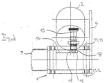
- FIG. 3 shows the parallelogram guide 6 according to FIGS. 1 and 2 in a top view.
- the pencil 18 automatically engages in the corresponding bore 16 of the leg 13 when the parallelogram guide 6 in the middle position or in the upper or lower End position. In order to release this locking of the parallelogram guide 6, the pin 18 can be pulled out of the bore 16 on the handle 19.
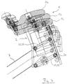
- Figure 4 shows a fastening device with spaced in the vertical direction Levers 30, 31, 32, 33, the lower levers 30, 31 being longer than the upper ones Levers 32, 33.
- levers 30-33 are on the Connection element 7 attached.
- a connection plate 34 is attached.
- the steering wheel 1 is connected to the steering valve 2 Connection plate 34 attached. Due to the different length of the levers 30, 31 and 32, 33 also changes its inclination when the steering wheel 1 is adjusted in height. The three possible positions are to illustrate this inclination adjustment 1a, 1b, 1c, in which the steering wheel 1 can be locked.
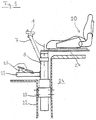
- Figure 5 shows an arrangement of the steering device in connection with a swiveling driver's seat.
- the driver's seat 20 is on a column 8 attached, which is rotatable in a frame 22 of the truck at a bearing 23 is stored.
- the column 8 is located in front of a rear block box 24 of the industrial truck, in which, for example, a battery pack or an internal combustion engine Drive unit can be arranged.
- a base plate 25 is fastened to the column in which Exemplary embodiment foot pedals 26 for controlling the driving movement of the industrial truck are arranged.
- foot pedals 26 for controlling the driving movement of the industrial truck are arranged.
- At the top of the column 8 is on one to the rear
- the driver's seat 20 extends over the mounting block 27 of the rear block box 24 attached.
- connecting element 7 is designed as a tube
- electrical and hydraulic line through the inside of the tube and the inside of the column 8 in the Area of the frame 22 of the truck can be performed.
- the arrangement according to FIG. 4 can also be used with a parallelogram guide according to FIGS. 1, 2 and 3 be combined.
- Figure 6 shows an industrial truck according to the invention, in which the steering device via a parallelogram guide 6 and a connecting piece 40 on a seat plate 41 the driver's seat 20 is attached.
- the steering device 6 is thus together with the Driver seat 20 rotatable about a column 8.
- the hydraulic from the steering valve Lines 5 are between the parallelogram guide 6 and the column 8 in guided a flexible hose 42.
- the steering device is pivoted the hose 42 with the hydraulic lines therein deforms when it for example abuts a battery case 43.
- the maximum swivel angle of the The steering device is compared to a solution with a rigid covering of the hydraulic lines (see Fig. 5) enlarged.
Landscapes
- Engineering & Computer Science (AREA)
- Transportation (AREA)
- Mechanical Engineering (AREA)
- Structural Engineering (AREA)
- Chemical & Material Sciences (AREA)
- Combustion & Propulsion (AREA)
- Civil Engineering (AREA)
- Life Sciences & Earth Sciences (AREA)
- Geology (AREA)
- Steering Controls (AREA)
- Forklifts And Lifting Vehicles (AREA)
Applications Claiming Priority (4)
| Application Number | Priority Date | Filing Date | Title |
|---|---|---|---|
| DE19847933 | 1998-10-19 | ||
| DE19847933 | 1998-10-19 | ||
| DE19939293 | 1999-08-19 | ||
| DE19939293A DE19939293A1 (de) | 1998-10-19 | 1999-08-19 | Flurförderzeug mit einer Lenkvorrichtung |
Publications (2)
| Publication Number | Publication Date |
|---|---|
| EP0995663A2 true EP0995663A2 (fr) | 2000-04-26 |
| EP0995663A3 EP0995663A3 (fr) | 2002-09-18 |
Family
ID=26049588
Family Applications (1)
| Application Number | Title | Priority Date | Filing Date |
|---|---|---|---|
| EP99120323A Withdrawn EP0995663A3 (fr) | 1998-10-19 | 1999-10-12 | Chariot de manutention avec un dispositif de direction |
Country Status (1)
| Country | Link |
|---|---|
| EP (1) | EP0995663A3 (fr) |
Cited By (5)
| Publication number | Priority date | Publication date | Assignee | Title |
|---|---|---|---|---|
| EP2022661A1 (fr) | 2007-08-08 | 2009-02-11 | Actia | Dispositif de réglage pour la position d'un tableau de bord et d'un volant associé |
| EP2857280A1 (fr) | 2013-10-07 | 2015-04-08 | NACCO Materials Handling Group, Inc. | Chariot élévateur à fourche avec des moyens de direction |
| EP3505485A1 (fr) * | 2017-12-21 | 2019-07-03 | OM Carrelli Elevatori S.p.A. | Chariot de manutention comportant un poste de travail de conducteur, en particulier un poste de conduite et un élément de commande conçu sous la forme de volant |
| US11987483B2 (en) | 2020-06-05 | 2024-05-21 | Crown Equipment Corporation | Operator control system for a materials handling vehicle |
| US11993497B2 (en) | 2015-11-09 | 2024-05-28 | Crown Equipment Corporation | Order picker materials handling vehicle with improved downward visibility when driving elevated |
Family Cites Families (9)
| Publication number | Priority date | Publication date | Assignee | Title |
|---|---|---|---|---|
| US2988931A (en) * | 1959-04-29 | 1961-06-20 | Grand Haven Stamped Prod | Folding steering column |
| NL285266A (fr) * | 1961-11-09 | 1900-01-01 | ||
| FR1401914A (fr) * | 1964-07-22 | 1965-06-04 | Hans Still Ag | Chariot élévateur ou véhicule tracteur analogue |
| US3737003A (en) * | 1971-05-03 | 1973-06-05 | Caterpillar Tractor Co | Adjustable control console for vehicles |
| US3800903A (en) * | 1972-01-17 | 1974-04-02 | Caterpillar Tractor Co | Coaxial steering wheels for an articulated motor grader |
| FR2440303A1 (fr) * | 1978-10-31 | 1980-05-30 | Fenwick Manutention Ste Indle | Vehicule, en particulier chariot de manutention, dont le volant est reglable en hauteur et en inclinaison |
| DE2908906A1 (de) * | 1979-03-07 | 1980-09-18 | Daimler Benz Ag | Fahrzeug, insbesondere nutzfahrzeug in frontlenkerbauweise |
| US5036942A (en) * | 1990-08-14 | 1991-08-06 | Ford New Holland, Inc. | Rotatable operator control unlocking mechanism |
| DE4119276A1 (de) * | 1991-06-12 | 1992-12-17 | Jungheinrich Ag | Vorrichtung zur lenkradverstellung in einem fahrzeug, insbesondere flurfoerderfahrzeug |
-
1999
- 1999-10-12 EP EP99120323A patent/EP0995663A3/fr not_active Withdrawn
Non-Patent Citations (1)
| Title |
|---|
| None |
Cited By (9)
| Publication number | Priority date | Publication date | Assignee | Title |
|---|---|---|---|---|
| EP2022661A1 (fr) | 2007-08-08 | 2009-02-11 | Actia | Dispositif de réglage pour la position d'un tableau de bord et d'un volant associé |
| FR2919842A1 (fr) * | 2007-08-08 | 2009-02-13 | Actia Sa | Dispositif de reglage pour la position d'un tableau de bord et d'un volant associe |
| EP2857280A1 (fr) | 2013-10-07 | 2015-04-08 | NACCO Materials Handling Group, Inc. | Chariot élévateur à fourche avec des moyens de direction |
| US9382105B2 (en) | 2013-10-07 | 2016-07-05 | Hyster-Yale Group, Inc. | Fork lift truck with steering means |
| US11993497B2 (en) | 2015-11-09 | 2024-05-28 | Crown Equipment Corporation | Order picker materials handling vehicle with improved downward visibility when driving elevated |
| EP3505485A1 (fr) * | 2017-12-21 | 2019-07-03 | OM Carrelli Elevatori S.p.A. | Chariot de manutention comportant un poste de travail de conducteur, en particulier un poste de conduite et un élément de commande conçu sous la forme de volant |
| US11987483B2 (en) | 2020-06-05 | 2024-05-21 | Crown Equipment Corporation | Operator control system for a materials handling vehicle |
| US12071333B2 (en) | 2020-06-05 | 2024-08-27 | Crown Equipment Corporation | Vertical viewing windows in a materials handling vehicle |
| US12577087B2 (en) | 2020-06-05 | 2026-03-17 | Crown Equipment Corporation | Operator control system for a materials handling vehicle |
Also Published As
| Publication number | Publication date |
|---|---|
| EP0995663A3 (fr) | 2002-09-18 |
Similar Documents
| Publication | Publication Date | Title |
|---|---|---|
| DE602004012744T2 (de) | Armlehne zur verwendung mit einem fahrzeugsitz | |
| DE3901051C2 (fr) | ||
| DE102015012560A1 (de) | Fahrstand für eine Baumaschine und Baumaschine mit einem Fahrstand | |
| EP1522633B1 (fr) | Fraiseuse de route avec dispositif de direction | |
| EP2369066A2 (fr) | Poste de travail d'utilisateur d'un engin | |
| DE29723095U1 (de) | Flurförderfahrzeug | |
| DE4316364A1 (de) | Mehrzweck-Arbeits-Fahrzeug | |
| DE2739537A1 (de) | Schwenkgabelanordnung fuer verladeausruestungen | |
| EP0286038A1 (fr) | Tablette pour véhicule automobile, en particulier pour la zone du tunnel de transmission, située entre les sièges d'un véhicule poids lourd | |
| EP1657400A1 (fr) | Appareil de construction | |
| DE102006015504A1 (de) | Sitz für einen Fahrzeugführer einer Baumaschine, sowie Baumaschine | |
| DE10250905B4 (de) | Verstelleinrichtung für ein Lenkrad eines Flurförderzeugs | |
| EP0754829A1 (fr) | Dispositif pour le raccordement d'un élément pivotant, p.ex. d'un capot de véhicule à un corps, p.ex. à un châssis de véhicule | |
| EP0995663A2 (fr) | Chariot de manutention avec un dispositif de direction | |
| DE69119491T2 (de) | Reinigungsfahrzeuge | |
| DE3003175A1 (de) | Gelenkbeschlag fuer fahrzeugsitze | |
| DE3938961A1 (de) | Teleskopierbare verstellung fuer aussenrueckspiegel an fahrzeugen | |
| EP0442067B1 (fr) | Machine agricole avec un outil de travail placé du côté avant ou du côté arrière | |
| DE2932344A1 (de) | Vorrichtung zur verstellung einer kopfstuetze | |
| DE4229459A1 (de) | Baufahrzeug | |
| EP1655450B1 (fr) | Appareil de forage | |
| DE19939293A1 (de) | Flurförderzeug mit einer Lenkvorrichtung | |
| DE102006001689A1 (de) | Deichsel für ein Flurförderzeug | |
| AT396798B (de) | Baumaschine mit einem anbauteil | |
| DE19604226A1 (de) | Hubstapler |
Legal Events
| Date | Code | Title | Description |
|---|---|---|---|
| PUAI | Public reference made under article 153(3) epc to a published international application that has entered the european phase |
Free format text: ORIGINAL CODE: 0009012 |
|
| AK | Designated contracting states |
Kind code of ref document: A2 Designated state(s): AT BE CH CY DE DK ES FI FR GB GR IE IT LI LU MC NL PT SE |
|
| AX | Request for extension of the european patent |
Free format text: AL;LT;LV;MK;RO;SI |
|
| RIC1 | Information provided on ipc code assigned before grant |
Free format text: 7B 62D 1/18 A, 7B 60N 2/14 B |
|
| PUAL | Search report despatched |
Free format text: ORIGINAL CODE: 0009013 |
|
| AK | Designated contracting states |
Kind code of ref document: A3 Designated state(s): AT BE CH CY DE DK ES FI FR GB GR IE IT LI LU MC NL PT SE |
|
| AX | Request for extension of the european patent |
Free format text: AL;LT;LV;MK;RO;SI |
|
| AKX | Designation fees paid | ||
| REG | Reference to a national code |
Ref country code: DE Ref legal event code: 8566 |
|
| STAA | Information on the status of an ep patent application or granted ep patent |
Free format text: STATUS: THE APPLICATION IS DEEMED TO BE WITHDRAWN |
|
| 18D | Application deemed to be withdrawn |
Effective date: 20030502 |