EP0995708A2 - Beutel-Wickelmaschine und Verfahren dazu - Google Patents
Beutel-Wickelmaschine und Verfahren dazu Download PDFInfo
- Publication number
- EP0995708A2 EP0995708A2 EP99308277A EP99308277A EP0995708A2 EP 0995708 A2 EP0995708 A2 EP 0995708A2 EP 99308277 A EP99308277 A EP 99308277A EP 99308277 A EP99308277 A EP 99308277A EP 0995708 A2 EP0995708 A2 EP 0995708A2
- Authority
- EP
- European Patent Office
- Prior art keywords
- spindle
- film
- air
- roll
- airhorn
- Prior art date
- Legal status (The legal status is an assumption and is not a legal conclusion. Google has not performed a legal analysis and makes no representation as to the accuracy of the status listed.)
- Granted
Links
- 238000000034 method Methods 0.000 title claims abstract description 9
- 238000004804 winding Methods 0.000 claims abstract description 26
- 238000011144 upstream manufacturing Methods 0.000 claims abstract description 13
- 239000000463 material Substances 0.000 claims abstract description 12
- 239000010687 lubricating oil Substances 0.000 claims abstract description 5
- 230000003068 static effect Effects 0.000 claims abstract description 4
- 238000012546 transfer Methods 0.000 claims description 15
- 230000003094 perturbing effect Effects 0.000 abstract 1
- 238000013461 design Methods 0.000 description 8
- 239000004033 plastic Substances 0.000 description 7
- 229920003023 plastic Polymers 0.000 description 7
- 230000007246 mechanism Effects 0.000 description 6
- 239000004809 Teflon Substances 0.000 description 4
- 229920006362 Teflon® Polymers 0.000 description 4
- 239000000314 lubricant Substances 0.000 description 4
- 230000004048 modification Effects 0.000 description 4
- 238000012986 modification Methods 0.000 description 4
- 239000004744 fabric Substances 0.000 description 3
- 229910000831 Steel Inorganic materials 0.000 description 2
- 238000007664 blowing Methods 0.000 description 2
- 230000008859 change Effects 0.000 description 2
- 238000009963 fulling Methods 0.000 description 2
- 239000010813 municipal solid waste Substances 0.000 description 2
- 238000004806 packaging method and process Methods 0.000 description 2
- 239000002985 plastic film Substances 0.000 description 2
- 229920002635 polyurethane Polymers 0.000 description 2
- 239000004814 polyurethane Substances 0.000 description 2
- 239000010959 steel Substances 0.000 description 2
- 229920006074 Nylatron® Polymers 0.000 description 1
- 239000012190 activator Substances 0.000 description 1
- 230000002411 adverse Effects 0.000 description 1
- XAGFODPZIPBFFR-UHFFFAOYSA-N aluminium Chemical compound [Al] XAGFODPZIPBFFR-UHFFFAOYSA-N 0.000 description 1
- 229910052782 aluminium Inorganic materials 0.000 description 1
- 238000013459 approach Methods 0.000 description 1
- 239000011248 coating agent Substances 0.000 description 1
- 238000000576 coating method Methods 0.000 description 1
- 238000010276 construction Methods 0.000 description 1
- 230000000694 effects Effects 0.000 description 1
- 229920001971 elastomer Polymers 0.000 description 1
- 238000005461 lubrication Methods 0.000 description 1
- 238000003754 machining Methods 0.000 description 1
- 229920006255 plastic film Polymers 0.000 description 1
- 229920001296 polysiloxane Polymers 0.000 description 1
- 230000009467 reduction Effects 0.000 description 1
- 238000012552 review Methods 0.000 description 1
- 238000007790 scraping Methods 0.000 description 1
- 239000002699 waste material Substances 0.000 description 1
Images


Classifications
-
- B—PERFORMING OPERATIONS; TRANSPORTING
- B65—CONVEYING; PACKING; STORING; HANDLING THIN OR FILAMENTARY MATERIAL
- B65H—HANDLING THIN OR FILAMENTARY MATERIAL, e.g. SHEETS, WEBS, CABLES
- B65H19/00—Changing the web roll
- B65H19/22—Changing the web roll in winding mechanisms or in connection with winding operations
- B65H19/2276—The web roll being driven by a winding mechanism of the coreless type
-
- B—PERFORMING OPERATIONS; TRANSPORTING
- B65—CONVEYING; PACKING; STORING; HANDLING THIN OR FILAMENTARY MATERIAL
- B65H—HANDLING THIN OR FILAMENTARY MATERIAL, e.g. SHEETS, WEBS, CABLES
- B65H2406/00—Means using fluid
- B65H2406/10—Means using fluid made only for exhausting gaseous medium
- B65H2406/11—Means using fluid made only for exhausting gaseous medium producing fluidised bed
-
- B—PERFORMING OPERATIONS; TRANSPORTING
- B65—CONVEYING; PACKING; STORING; HANDLING THIN OR FILAMENTARY MATERIAL
- B65H—HANDLING THIN OR FILAMENTARY MATERIAL, e.g. SHEETS, WEBS, CABLES
- B65H2408/00—Specific machines
- B65H2408/20—Specific machines for handling web(s)
- B65H2408/23—Winding machines
- B65H2408/231—Turret winders
- B65H2408/2315—Turret winders specified by number of arms
- B65H2408/23155—Turret winders specified by number of arms with three arms
-
- B—PERFORMING OPERATIONS; TRANSPORTING
- B65—CONVEYING; PACKING; STORING; HANDLING THIN OR FILAMENTARY MATERIAL
- B65H—HANDLING THIN OR FILAMENTARY MATERIAL, e.g. SHEETS, WEBS, CABLES
- B65H2701/00—Handled material; Storage means
- B65H2701/10—Handled articles or webs
- B65H2701/19—Specific article or web
- B65H2701/191—Bags, sachets and pouches or the like
Definitions
- the present invention relates generally to the art of winding equipment. More specifically, it relates to equipment for winding strips of elongate, pliable material, such as paper or plastic, into core or coreless rolls.
- a continuous strip of bags is fed to the winder, and the winder prepares coreless rolls therefrom.
- the bags themselves are produced in upstream bag making equipment or on a separate piece of equipment, from which a continuous strip of bags is produced.
- a tube of plastic film is extruded through an extruding die, and the tube is then flattened before it enters the bag machine.
- the film is sealed across its width to form the bottom of the finished product.
- the open top of the bag can be formed in different ways. For example, the bag can simply be cut. In this type of bag machine, individual bags are formed which are typically folded and placed into suitable packaging for the individual or institutional consumer. In the other type of bag machine, the top is formed by perforating the bag across its width. The bag may then be folded longitudinally, either before or after the perforation step, to provide a continuous strip of connected and folded bags. Such bags are then wound into a core or coreless roll.
- Such winder includes a dancer mechanism to sense the tension of the strip of bags being fed to the winder.
- the dancer mechanism includes a connection to the winder drive motor, wherein the speed of the winder can be "slaved" to the output speed of an upstream bag making equipment.
- the prior art winder also includes haul-off nip rollers, to feed the strip into the winder, and an interrupt section to periodically break the perforations between certain bags in the strip.
- the frequency of the interruption is determined by the number of bags to be included in each roll. For example, if the roll is to contain twenty bags, the interrupt section will break every twentieth perforation.
- the prior art winder Downstream of these sections, the prior art winder includes a turret assembly with three spindles mounted 120° apart. To begin winding a roll of bags the leading end of one strip of bags is directed to a first spindle when the turret is in a transfer position. After the bag is secured to the spindle by a transfer mechanism such as that described in U.S. Patent No. 4,667,890, incorporated herein by reference, the turret is rotated 120° so that the first spindle is in a winding position and the strip is wound into a coreless roll. Following completion of the roll winding, the turret rotates again to a removal station where the roll is pushed off the first spindle by a push-off palm for subsequent packaging. When the winding of the one roll is completed the leading end of the film is directed to a second spindle in the transfer position.
- a variety of prior art mechanisms are used to direct the leading end of a strip to the spindle.
- an airhorn and kick-roll mechanism were used to effect the transfer.
- the kick-roll is a pneumatic activated roller located beneath a traveling belt at the area near the transfer location. At the time of transfer, the roller would be extended by a piston rod to quickly push against the belt to "flip" the leading edge of the strip of bags up into the air above the lower belt.
- an airhorn would descend around the spindle, the airhorn being a half-cylinder containing air ports on one edge. The combination was intended to direct the leading edge of the bag strip around the spindle and tuck it into its own nip to create the attachment.
- a winder which economically and effectively transferred a leading edge of a strip of plastic to a spindle would represent a significant advance in the art.
- Such a winder will preferably be easy to set up.
- Prior art designs often used compressed air injected into a spindle at the unloading position to lubricate the spindle surface to make roll removal easier. (See, for example, U.S. Patent No. 5,337,968).
- Another prior art feature intended to make roll removal easier is a tapered spindle.
- Prior art spindles often provided a large taper, such as about 0.06 in. diameter reduction per foot, in the belief that it would make removal of roll 302 easier.
- Prior art spindles failed to properly account for the proper ratio of air inlet area to air outlet area of the spindle when designing the air lubricant system. For example, some prior art designs were unable to build up a sufficiently large back pressure at the face of the spindle, thus they were unable to force the roll to expand enough to float on a cushion of air.
- the air lubricant system typically included a plurality of air holes through which air can be selectively injected.
- a spindle design that provides for an effective and easy removal is desirable.
- Such a system should have a suitable back pressure.
- Roll removal is typically performed by a push-off palm (after the air lubrication is provided).
- a prior art push palm plate used by the assignee of this invention included a slot without contact with the spindle.
- the spindle can be surrounded by the palm in one quadrant, or all four quadrants.
- four quadrant palms have excessive moving parts to move into position, and are thus prone to failure. Accordingly, a push-off palm that properly pushes a roll off, without being prone to failure, is desired.
- an apparatus for winding film includes a pair of haul-in rolls, a rotatable spindle, and an airhorn.
- the airhorn is movable to be disposed over the spindle.
- a film guide is located on the upstream side of the airhorn (i.e. the upstream film path before the film enters the airhorn), and guides a leading edge of the film back into its own nip.
- an apparatus for winding film includes a pair of haul-in rolls, a rotatable spindle, and an airhorn.
- the airhorn is movable to be disposed over the spindle.
- An air guide is located between the air horn and the film path leading to the spindle, and keeps air from moving out of the airhorn and upstream.
- a winder for film includes a pair of haul-in rolls and a conveyor to transport the film from the haul-in rolls to the airhorn.
- a rotatable spindle, and an airhorn that moves to the spindle are also included.
- a mounting block is attached to the downstream side of the airhorn, and above the conveyor. Compressed air is injected into the mounting block, and it causes air flow between the conveyor and the block, and from the source of air to the air horn, thus creating a curtain of air downstream of the spindle, such that air directs the leading edge of the film into the airhorn and towards the spindle.
- One embodiment provides a kick-roll downstream of the spindle.
- Another embodiment provides holes in the film guide so that air may exit the air horn through the holes or so that deflectors may be inserted through the holes to further direct the leading edge of the film into its own nip.
- One alternative embodiment has the air and film guides being made of non-stick materials.
- Another embodiment provides for a static pinner to pin or cling the leading edge of the film to the spindle.
- the spindle has a winding surface, and the winding surface diameter is tapered by about 0.014 inches per foot or less.
- the spindle has an air inlet, and a plurality of holes in other embodiments.
- the inlet area is greater than the hole area, at least about four times greater than the hole area, or at least about seven times greater than the hole area in various alternatives.
- the spindle may be coated with a non-stick surface or have a liquid lubricant applied thereto.
- a roll remover is disposed at a roll removal position, and the roll remover contacts the spindle and pushes off the wound roll.
- the roll remover may be a yoke or a palm, and may contact the spindle at one or more points, over a portion of the spindle, or over substantially 360 degrees.
- the present invention will be illustrated with reference to its use as a winder for strips of plastic bags, it should be understood at the outset that the winder can also be employed for winding other pliable materials, such as paper or plastic sheets.
- the material being wound should have sufficient tear strength to be able to withstand the winding forces imposed at the transfer and surface-wind stations.
- plastic sheeting, paper and tissue products and the like could be wound using the winder of the present invention after appropriate modification, which would be readily apparent to one skilled in the art after reading the present disclosure.
- the winder of the present invention is designed to be used with a rotary bag making machine, although it could be used with other types of machines.
- the winder includes a turret with a plurality of spindles mounted thereon, such as that used in the prior art.
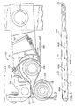
- Figure 1 is a prior art winder and includes a turret assembly 106, where the film travels from right to left. The details of the prior art design are described in Application Ser. No. 08/662,311.
- turret assembly 106 includes 4 (rather than 3) spindles 131-133.
- FIG. 2 shows an air horn assembly 200, including a horn 210 mounted on an arm 211, which pivots about a pivot point 212.
- Air horn assembly 200 also includes a pair of guides 202 and 204, and an air curtain 214 which is attached to air horn 210.
- a spindle 206 which may be an inventive spindle as described below or a prior art spindle, and a kick roll 205 (such as in the prior art).
- a belt, ropes, or other film conveyor 208 are shown and are used to guide the film from right to left into the airhorn.
- Guide 202 is a non-stick material, such as a teflon coated fabric, shaped in one part as a curve to help form the airhorn, and in another part generally straight. (As used herein a material is non-stick if the co-efficient of friction between the material and the film is less than the co-efficient of friction between the film and polished steel). It is bolted by a plurality of bolts 201 (that extend in the direction perpendicular to the paper) at the end of the curved portion and onto bracket 203 along the straight portion.
- Guide 204 is also a teflon coated fabric, and is bolted at one end to bracket 203, and at the other end terminates slightly beyond the inflection point of guide 202.
- airhorn assembly 200 is pivoted downward to spindle 206.
- the film path is from right to left and as the film moves under air horn assembly 200 it approaches kick roll 205, which kicks the film up and, in cooperation with an air curtain in the preferred embodiment, directs the leading edge of the film into the air horn.
- the preferred embodiment includes an air curtain 214.
- Air curtain 214 is created by a piece of aluminum 215 mounted to block 216 such that a gap of 0.002 in, gap 219 exists therebetween. Air is provided through block 216 such that it leaks out gap 219. The air follows the surface of block 216, and flows between the surface of block 216 and belt 208, as shown by arrow 217, and travels into the air horn, thus forming the air curtain.
- the air curtain directs and holds the film to the roll from about the 9:00 to 2:00 positions.
- air movement around the airhorn is such that the leading edge of the film is pulled into the downstream side of the airhorn by air movement (which cooperates with the kick roll).
- the film typically contacts spindle 206 at about the nine-o-clock position.
- the film travels with the spindle, and is held to the spindle by air from the air curtain until about the two or three o'clock position, where it has a tendency to peel away from spindle 206.
- Guide or deflector 202 directs the film downward.
- Guides 202 and 204 are teflon in the preferred embodiment so that there is little friction between it and the film.
- One or both of guides 202 and 204 are made of other material, or omitted, in alternative embodiments.
- the air moving around spindle 206 has the tendency to go in the upstream direction (upstream refers to the film path before the film reaches the airhorn) at about the 4:30 position.
- upstream refers to the film path before the film reaches the airhorn
- the air would travel along the surface of the incoming web, and can bring the leading edge with it. Of course, this would have an adverse impact on the starting of a roll to be wound.
- air guide or shield 204 seals the air away from the upstream direction and around the spindle, thus helping to direct the web around the spindle so that it forms a nip with itself and begins to wind.
- Guide 204 is comprised of a thicker, heavier material than a teflon fabric in one embodiment, and is omitted in another embodiment.
- Alternative designs include a series of holes through guide 202, for example at the location marked 207 on Figure 2, where the holes extend in a plane perpendicular to the view shown.
- the holes provide an escape for air so that the film is disturbed less in the tucking area at the bottom of the spindle.
- the holes may be close (0.25-0.5 inches, e.g.) to the crease of guide 202. Absent this alternative, air will escape out the ends of airhorn 210 (in the planes parallel to the Figure).
- Another alternative is to have fingers extending through holes to tuck the film into a nip. The holes with the fingers therein could be located at 207 on Figure 2.
- Yet another alternative is to use a static pinner as part of the air horn to pin or cling the film to a grounded spindle.
- the preferred embodiment provides that the distances between the various parts are preferably not critical, in that a range of distances and angles will suffice. Generally, the user should empirically determine the best distances and angles (or ranges thereof) for the particular equipment used to implement the invention. While distances appear to be less critical with this invention than with the prior art, the inventors have determined that a distance of about 0.25-0.31 inches from the airhorn to the spindle and about 0.19 inches from kick roll 205 to block 216 works well for equipment made by the assignee of this invention.
- FIG. 1 is a schematic of a spindle and roll that illustrates the operating principles of this aspect of the invention.
- Figures 4-6 are drawings of a spindle constructed in accordance with this invention.
- Figure 3 includes a spindle 301 and a roll of wound film 302, after the film has been pushed away from spindle 301 by air pressure.
- the relative sizes, angles, dimensions, and positions of spindle 301 and roll 302 are exaggerated for purposes of illustration.
- Spindle 301 includes an air inlet 304, and a plurality of holes 305. Air is provided through air inlet 304, and exits spindle 301 through holes 305. The air creates a pressure against roll 302, that forces roll 302 outward and thus creating a cushion of lubricant so that roll 302 may be more easily removed.
- the air exhausts through an annulus 306, between roll 302 and the end of spindle 301.
- the pressure that is exerted on roll 302 depends upon the pressure of the air supply, the cross-sectional area of air inlet 304 (inlet area), the combined cross-sectional areas of outlet holes 305 (hole area), and the area of annulus 306 (escape area). Thus, these areas (and the taper of spindle 301 which determines the area of annulus 306) should be chosen such that a desired pressure is exerted on roll 302.
- the optimal ratio and Pin may depend on the equipment being used, the weight of the film being wound, and other parameters.
- the preferred embodiment provides that a Pin of 60 PSI is preferable for low density polyurethane and a Pin of 40 PSI is preferable for high density polyurethane. This is obtained by using a 90 PSI source, a 7:1 ratio of inlet area to hole area, and a regulator to regulate down the source pressure to obtain the desired Pin.
- FIG. 4 is a front view of a spindle 400
- Figure 5 and 6 are section taken along lines 5-5, and 6-6, respectively.
- Spindle 400 is mounted to the turret at an end 401, through which air is provided into spindle 400.
- an air source located at that position seals against a rubber grommet at end 401 of the spindle.
- a plurality of holes 404 are shown, and the film is wound about the portion on which the holes are mounted.
- the preferred embodiment provides a taper of about 0.06 inches change in diameter per foot. In various alternatives a lesser taper of about 0.03 inches, or about 0.015 inches or less, is provided. Thus, the left end of spindle 400 of Figure 4 is narrower than the right end.
- Holes 404 are disposed over the entire area about which the film roll is wrapped (i.e., the winding surface) in the preferred embodiment (although other arrangements may be used).
- the film is wrapped generally from the change in diameter near 406 to the far left end of spindle 400 in the preferred embodiment (12 inches e.g.).
- Spindle 406 is mounted in bearings just to the right of 406, in the preferred embodiment.
- a push off palm (such as the inventive push off palm described below, or a push off palm of the type known in the prior art) is disposed on the shaft to the left of 406.
- Holes 404 are preferably counter-sunk, which increases the surface area which has the Pin pressure applied thereto. There are 22 holes in the preferred embodiment, each about 0.02 inch diameter.
- the air inlet at end 401 has a diameter of about 1/4 inch. This yields an inlet area of about 0.049 in 2 , and a hole area of about 0.007 in 2 , for about a 7:1 ratio.
- the spindle surface finish is polished to remove machining lines and to smooth the edges of the counter-sink of holes 404 such that the wrapped film will not settle into a circular groove or stick to the countersinks.
- a permanent surface coating which is non-stick is applied to the spindle. This allows for a more easily removable roll.
- a liquid lubricant such as silicone, on the surface of the spindle each time the machine cycles.
- FIG. 7 shows one embodiment of a yoke 501 mounted about a spindle 502 that provides a full 360 degrees of contact to spindle 501.
- the yoke may be moved by a traditional push-off palm (which does not contact the spindle at all since the yoke contacts the spindle).
- yoke 501 may be moved by an activator at the unloading station.
- Yoke 501 primarily pushes the rolls inner layers from the spindle.
- Yoke 501 has a small outer diameter (relative to the roll diameter) to prevent pushing outer layers of the roll if the roll is telescoped. Yoke 501 is slightly undersized so that it stays tight to spindle 502, even if spindle 502 is tapered. Alternatives to a complete contact is having two or more segments in contact, with gaps therebetween.
- One alternative embodiment is to use one or more points of contact between the palm and the spindle. However, if the palm touches at only one point or on only one side, then the roll can cock and lock onto the spindle. Thus, preferred embodiments use a multiple point contact. For example, a two contact palm should avoid cocking the roll if the two points are offset by 180 degrees. Other alternatives include three, four, or more, preferably equally spaced, contact points. However, a two point contact palm may be simpler, easier to make, and less prone to failure than a four point (or four quadrant) palm.
- Figure 8 shows a two point contact palm 600, having four slots 602-605 thereon. Each slot is similarly designed, and functions similarly. Thus, only slot 603 will be described.
- Two contact points 607 and 608 are shown. Palm 600 includes steel behind the contact points, for added support.
- the contact points are made of 1/2 inch THK Nylatron GSM® in one embodiment.
- the spindle slips within each slot, contacting sides 607 and 608, but leaving a small (0.06 in., e.g.) between the spindle and the inside of the slot (609).
Landscapes
- Winding Of Webs (AREA)
- Registering, Tensioning, Guiding Webs, And Rollers Therefor (AREA)
- Advancing Webs (AREA)
Applications Claiming Priority (2)
| Application Number | Priority Date | Filing Date | Title |
|---|---|---|---|
| US176364 | 1998-10-21 | ||
| US09/176,364 US6186436B1 (en) | 1998-10-21 | 1998-10-21 | Bag winder and method thereof |
Publications (3)
| Publication Number | Publication Date |
|---|---|
| EP0995708A2 true EP0995708A2 (de) | 2000-04-26 |
| EP0995708A3 EP0995708A3 (de) | 2000-09-27 |
| EP0995708B1 EP0995708B1 (de) | 2003-10-01 |
Family
ID=22644057
Family Applications (1)
| Application Number | Title | Priority Date | Filing Date |
|---|---|---|---|
| EP99308277A Expired - Lifetime EP0995708B1 (de) | 1998-10-21 | 1999-10-20 | Beutel-Wickelmaschine und Verfahren dazu |
Country Status (4)
| Country | Link |
|---|---|
| US (1) | US6186436B1 (de) |
| EP (1) | EP0995708B1 (de) |
| DE (1) | DE69911714T2 (de) |
| ES (1) | ES2209346T3 (de) |
Cited By (6)
| Publication number | Priority date | Publication date | Assignee | Title |
|---|---|---|---|---|
| DE10116973A1 (de) * | 2001-04-05 | 2002-10-17 | Reifenhaeuser Masch | Wickeleinrichtung sowie Verfahren zur Durchführung eines Wickelwellenwechsels in einer Wickeleinrichtung |
| WO2006012933A1 (en) * | 2004-08-05 | 2006-02-09 | No.El. S.R.L. | Method and apparatus for winding and removing coreless rolls from a spindle |
| US7036763B2 (en) | 2002-10-25 | 2006-05-02 | REIFENHäUSER GMBH & CO. MASCHINENFABRIK | Winding apparatus and method for performing a change of winding tube in a winding apparatus |
| US8286904B2 (en) | 2009-05-18 | 2012-10-16 | No. El. S.R.L. | Method, mandrel and apparatus for winding up and removing coreless rolls of stretch film |
| US8292212B2 (en) | 2009-06-25 | 2012-10-23 | No. El. S.R.L. | Method, mandrel and device for the removal of coreless rolls of a stretch film |
| WO2014060124A1 (de) * | 2012-10-18 | 2014-04-24 | Espera-Werke Gmbh | Etikettiermaschine mit aufwickelvorrichtung für trägerband |
Families Citing this family (20)
| Publication number | Priority date | Publication date | Assignee | Title |
|---|---|---|---|---|
| US6305635B1 (en) * | 1997-07-30 | 2001-10-23 | Windmoeller & Hoelscher Kg | Continuous web winding method and device with suction-induced winding start of empty core mandrels |
| US7273193B2 (en) | 2003-02-04 | 2007-09-25 | Waverly Plastics Company, Inc. | Plastic bag dispensing unit |
| US7066422B1 (en) | 2003-02-04 | 2006-06-27 | Waverly Plastics | Axial center dispensing plastic sheet roll and method of use |
| US20040199975A1 (en) * | 2003-02-14 | 2004-10-14 | Terrance Kehrli | Water protective over garment |
| US20050150996A1 (en) * | 2004-01-12 | 2005-07-14 | Harald Schmidt-Hebbel | Reel spool shaft for use with cores |
| US20060084559A1 (en) * | 2004-10-19 | 2006-04-20 | Paul Selle | Rotary bag machine |
| US20070045463A1 (en) * | 2005-08-25 | 2007-03-01 | White Christopher L | Bag machine having a spindle |
| US7445590B2 (en) | 2006-01-13 | 2008-11-04 | Cmd Corporation | Method and apparatus for making bags |
| MX2008009071A (es) * | 2006-01-13 | 2009-05-13 | Cmd Corp | Metodo y aparato para fabricar bolsas. |
| US10279557B2 (en) | 2006-01-13 | 2019-05-07 | Cmd Corporation | Method and apparatus for making skirtless seals |
| US8029428B2 (en) * | 2006-01-13 | 2011-10-04 | Cmd Corporation | Method and apparatus for making skirtless seals |
| US7578779B2 (en) * | 2006-09-14 | 2009-08-25 | Cmd Corporation | Bag machine and winder |
| US20090019817A1 (en) * | 2006-09-14 | 2009-01-22 | Cmd Corporation | Bag Machine And Winder |
| US8308625B2 (en) * | 2009-08-16 | 2012-11-13 | Ips Industries, Inc. | Apparatus configured to manufacture a roll of interleaved bags |
| ITMI20110467A1 (it) | 2011-03-24 | 2012-09-25 | No El Srl | Mandrino per l'avvolgimento di bobine senz'anima di un film plastico |
| US9925734B2 (en) * | 2011-04-20 | 2018-03-27 | Cmd Corporation | Method and apparatus for making bags |
| ES1204140Y (es) | 2018-01-08 | 2018-04-23 | Construcciones Electromecanicas Del Ter S A | Husillo para máquinas bobinadoras de bolsas sin núcleo |
| ES1204713Y (es) | 2018-01-08 | 2018-04-30 | Construcciones Electromecanicas Del Ter S A | Dispositivo para el iniciado de bobinas en máquinas bobinadoras de bolsas sin núcleo |
| ES1204736Y (es) | 2018-01-08 | 2018-04-30 | Construcciones Electromecanicas Del Ter S A | Devanadora de bolsas sin nucleo |
| WO2020206436A1 (en) * | 2019-04-04 | 2020-10-08 | Reynolds Consumer Products LLC | Assembly system and method for packaging web material in a roll |
Family Cites Families (14)
| Publication number | Priority date | Publication date | Assignee | Title |
|---|---|---|---|---|
| FR1536314A (fr) * | 1967-06-29 | 1968-08-10 | Spidem Ste Nle | Dispositif d'enroulement sur mandrin |
| US3802639A (en) * | 1972-01-10 | 1974-04-09 | Westvaco Corp | Method and apparatus for coreless spool production |
| US3908924A (en) * | 1973-05-16 | 1975-09-30 | Greene Gmbh & Co Kg Maschbau | Winding machines |
| IT1047341B (it) * | 1975-10-03 | 1980-09-10 | Sant Andrea Novara Officine | Dispositivo automatico per l applicazione di contrassegni di identificazione su un rocchetto o rullino di una sostanza tessile |
| JPS56149941A (en) * | 1980-04-21 | 1981-11-20 | Fuji Tekkosho:Kk | Winder with multiple type turret |
| US4667890A (en) | 1985-07-15 | 1987-05-26 | Custom Machinery Design, Inc. | Coreless winder |
| US5131592A (en) * | 1989-01-30 | 1992-07-21 | Brother Kogyo Kabushiki Kaisha | Automatic winding mechanism for a continuous sheet and the like |
| US5016833A (en) * | 1990-03-16 | 1991-05-21 | Xerox Corporation | Document roll-up system |
| DE4010894C2 (de) * | 1990-04-04 | 1996-11-28 | Fmc Corp | Revolverkopfaufwickel-Vorrichtung zum Aufwickeln von Bahnmaterial, insbesondere von aus Kunststoffolien bestehenden, in Bandform zusammenhängenden Beuteln |
| US5318237A (en) | 1992-10-08 | 1994-06-07 | Fmc Corporation | Air horn for web winding machine |
| US5899403A (en) * | 1994-05-24 | 1999-05-04 | Cmd Corporation | Method and apparatus for winding bags onto a spindle |
| DE69623088T2 (de) * | 1995-09-18 | 2003-04-03 | Noritsu Koki Co., Ltd. | Automatisches Filmentladegerät und Zwischenladekassette für Film in einem automatischen Filmentwicklungsgerät |
| CA2205795A1 (en) * | 1996-05-31 | 1997-11-30 | Scott C. Romenesko | Roll-forming apparatus for continuous or interleaved webs |
| US5797559A (en) * | 1996-09-18 | 1998-08-25 | Ncr Corporation | Winding arbor having a plurality of air valves for making coreless paper rolls and method for using |
-
1998
- 1998-10-21 US US09/176,364 patent/US6186436B1/en not_active Expired - Lifetime
-
1999
- 1999-10-20 EP EP99308277A patent/EP0995708B1/de not_active Expired - Lifetime
- 1999-10-20 ES ES99308277T patent/ES2209346T3/es not_active Expired - Lifetime
- 1999-10-20 DE DE69911714T patent/DE69911714T2/de not_active Expired - Lifetime
Cited By (11)
| Publication number | Priority date | Publication date | Assignee | Title |
|---|---|---|---|---|
| DE10116973A1 (de) * | 2001-04-05 | 2002-10-17 | Reifenhaeuser Masch | Wickeleinrichtung sowie Verfahren zur Durchführung eines Wickelwellenwechsels in einer Wickeleinrichtung |
| US6752348B2 (en) | 2001-04-05 | 2004-06-22 | REIFENHäUSER GMBH & CO. MASCHINENFABRIK | Winding device, and method for performing a winding shaft change in a winding device |
| DE10116973B4 (de) * | 2001-04-05 | 2005-11-17 | Reifenhäuser GmbH & Co Maschinenfabrik | Wickeleinrichtung |
| US7036763B2 (en) | 2002-10-25 | 2006-05-02 | REIFENHäUSER GMBH & CO. MASCHINENFABRIK | Winding apparatus and method for performing a change of winding tube in a winding apparatus |
| WO2006012933A1 (en) * | 2004-08-05 | 2006-02-09 | No.El. S.R.L. | Method and apparatus for winding and removing coreless rolls from a spindle |
| US7641141B2 (en) | 2004-08-05 | 2010-01-05 | No. El. S.R.L. | Method and apparatus for winding and removing coreless rolls from a spindle |
| US8286904B2 (en) | 2009-05-18 | 2012-10-16 | No. El. S.R.L. | Method, mandrel and apparatus for winding up and removing coreless rolls of stretch film |
| US8292212B2 (en) | 2009-06-25 | 2012-10-23 | No. El. S.R.L. | Method, mandrel and device for the removal of coreless rolls of a stretch film |
| WO2014060124A1 (de) * | 2012-10-18 | 2014-04-24 | Espera-Werke Gmbh | Etikettiermaschine mit aufwickelvorrichtung für trägerband |
| CN104736440A (zh) * | 2012-10-18 | 2015-06-24 | 艾斯普拉工厂有限公司 | 具有为承载带而设的卷绕设备的贴标签机 |
| US9751652B2 (en) | 2012-10-18 | 2017-09-05 | Espera-Werke Gmbh | Labelling machine with winding device for a carrier film |
Also Published As
| Publication number | Publication date |
|---|---|
| EP0995708A3 (de) | 2000-09-27 |
| DE69911714T2 (de) | 2004-07-22 |
| ES2209346T3 (es) | 2004-06-16 |
| DE69911714D1 (de) | 2003-11-06 |
| EP0995708B1 (de) | 2003-10-01 |
| US6186436B1 (en) | 2001-02-13 |
Similar Documents
| Publication | Publication Date | Title |
|---|---|---|
| EP0995708B1 (de) | Beutel-Wickelmaschine und Verfahren dazu | |
| AU2014213508B2 (en) | Bag machine and winder | |
| US20070117703A1 (en) | Machine and method for converting a web of material into dunnage | |
| AU2005218026A1 (en) | Multiprocessing apparatus for forming logs of web material and log manufacture process | |
| US6561064B1 (en) | Method and apparatus for slitting a sheet material web | |
| US8002944B2 (en) | Method of placing a material transversely on a moving web | |
| AU2007295053B2 (en) | Bag machine and winder | |
| US5899403A (en) | Method and apparatus for winding bags onto a spindle | |
| US5069659A (en) | Apparatus for the production of shopping bags having reinforced handle holes | |
| US4300977A (en) | Machine for welding thermoplastic sheets | |
| US4499801A (en) | Web slitting and grooving method | |
| JP2002096327A (ja) | 積層フィルムの分離装置及び製造方法 | |
| US5913983A (en) | Edge vacuum system for removing slitter skivings from a running web | |
| JPH037583B2 (de) | ||
| CA2441325C (en) | Method and apparatus for trimming sheet metal | |
| JP2003504292A (ja) | フライング式のロール交換に続いてフラップを短くするための方法および装置 | |
| JP2010194634A (ja) | 連続紙のスリット耳屑ガイド装置 |
Legal Events
| Date | Code | Title | Description |
|---|---|---|---|
| PUAI | Public reference made under article 153(3) epc to a published international application that has entered the european phase |
Free format text: ORIGINAL CODE: 0009012 |
|
| AK | Designated contracting states |
Kind code of ref document: A2 Designated state(s): BE DE ES FR GB IT |
|
| AX | Request for extension of the european patent |
Free format text: AL;LT;LV;MK;RO;SI |
|
| PUAL | Search report despatched |
Free format text: ORIGINAL CODE: 0009013 |
|
| AK | Designated contracting states |
Kind code of ref document: A3 Designated state(s): AT BE CH CY DE DK ES FI FR GB GR IE IT LI LU MC NL PT SE |
|
| AX | Request for extension of the european patent |
Free format text: AL;LT;LV;MK;RO;SI |
|
| 17P | Request for examination filed |
Effective date: 20010208 |
|
| AKX | Designation fees paid |
Free format text: BE DE ES FR GB IT |
|
| 17Q | First examination report despatched |
Effective date: 20020723 |
|
| GRAH | Despatch of communication of intention to grant a patent |
Free format text: ORIGINAL CODE: EPIDOS IGRA |
|
| GRAS | Grant fee paid |
Free format text: ORIGINAL CODE: EPIDOSNIGR3 |
|
| GRAA | (expected) grant |
Free format text: ORIGINAL CODE: 0009210 |
|
| AK | Designated contracting states |
Kind code of ref document: B1 Designated state(s): BE DE ES FR GB IT |
|
| REG | Reference to a national code |
Ref country code: GB Ref legal event code: FG4D |
|
| REF | Corresponds to: |
Ref document number: 69911714 Country of ref document: DE Date of ref document: 20031106 Kind code of ref document: P |
|
| REG | Reference to a national code |
Ref country code: ES Ref legal event code: FG2A Ref document number: 2209346 Country of ref document: ES Kind code of ref document: T3 |
|
| ET | Fr: translation filed | ||
| PLBE | No opposition filed within time limit |
Free format text: ORIGINAL CODE: 0009261 |
|
| STAA | Information on the status of an ep patent application or granted ep patent |
Free format text: STATUS: NO OPPOSITION FILED WITHIN TIME LIMIT |
|
| 26N | No opposition filed |
Effective date: 20040702 |
|
| REG | Reference to a national code |
Ref country code: FR Ref legal event code: PLFP Year of fee payment: 18 |
|
| REG | Reference to a national code |
Ref country code: FR Ref legal event code: PLFP Year of fee payment: 19 |
|
| REG | Reference to a national code |
Ref country code: FR Ref legal event code: PLFP Year of fee payment: 20 |
|
| PGFP | Annual fee paid to national office [announced via postgrant information from national office to epo] |
Ref country code: FR Payment date: 20180913 Year of fee payment: 20 |
|
| PGFP | Annual fee paid to national office [announced via postgrant information from national office to epo] |
Ref country code: BE Payment date: 20180914 Year of fee payment: 20 |
|
| PGFP | Annual fee paid to national office [announced via postgrant information from national office to epo] |
Ref country code: DE Payment date: 20181009 Year of fee payment: 20 |
|
| PGFP | Annual fee paid to national office [announced via postgrant information from national office to epo] |
Ref country code: ES Payment date: 20181102 Year of fee payment: 20 Ref country code: IT Payment date: 20181018 Year of fee payment: 20 Ref country code: GB Payment date: 20181017 Year of fee payment: 20 |
|
| REG | Reference to a national code |
Ref country code: DE Ref legal event code: R071 Ref document number: 69911714 Country of ref document: DE |
|
| REG | Reference to a national code |
Ref country code: GB Ref legal event code: PE20 Expiry date: 20191019 |
|
| REG | Reference to a national code |
Ref country code: BE Ref legal event code: MK Effective date: 20191020 |
|
| PG25 | Lapsed in a contracting state [announced via postgrant information from national office to epo] |
Ref country code: GB Free format text: LAPSE BECAUSE OF EXPIRATION OF PROTECTION Effective date: 20191019 |
|
| REG | Reference to a national code |
Ref country code: ES Ref legal event code: FD2A Effective date: 20200721 |
|
| PG25 | Lapsed in a contracting state [announced via postgrant information from national office to epo] |
Ref country code: ES Free format text: LAPSE BECAUSE OF EXPIRATION OF PROTECTION Effective date: 20191021 |