EP0995805A1 - Wärmebehandlungsanlage für eine Charge metallischer Werkstücke - Google Patents
Wärmebehandlungsanlage für eine Charge metallischer Werkstücke Download PDFInfo
- Publication number
- EP0995805A1 EP0995805A1 EP98811062A EP98811062A EP0995805A1 EP 0995805 A1 EP0995805 A1 EP 0995805A1 EP 98811062 A EP98811062 A EP 98811062A EP 98811062 A EP98811062 A EP 98811062A EP 0995805 A1 EP0995805 A1 EP 0995805A1
- Authority
- EP
- European Patent Office
- Prior art keywords
- oven
- installation according
- load
- installation
- tank
- Prior art date
- Legal status (The legal status is an assumption and is not a legal conclusion. Google has not performed a legal analysis and makes no representation as to the accuracy of the status listed.)
- Granted
Links
- 238000009434 installation Methods 0.000 title claims abstract description 95
- 238000010438 heat treatment Methods 0.000 title claims description 11
- 230000003647 oxidation Effects 0.000 claims abstract description 5
- 238000007254 oxidation reaction Methods 0.000 claims abstract description 5
- 238000001816 cooling Methods 0.000 claims description 30
- 238000011068 loading method Methods 0.000 claims description 26
- 238000013519 translation Methods 0.000 claims description 4
- 239000007788 liquid Substances 0.000 claims description 3
- 239000002184 metal Substances 0.000 claims description 3
- 239000002826 coolant Substances 0.000 claims 1
- 230000000712 assembly Effects 0.000 abstract 2
- 238000000429 assembly Methods 0.000 abstract 2
- 230000008878 coupling Effects 0.000 abstract 1
- 238000010168 coupling process Methods 0.000 abstract 1
- 238000005859 coupling reaction Methods 0.000 abstract 1
- 238000007669 thermal treatment Methods 0.000 abstract 1
- 238000011282 treatment Methods 0.000 description 23
- 239000007789 gas Substances 0.000 description 21
- 238000002360 preparation method Methods 0.000 description 7
- 230000001143 conditioned effect Effects 0.000 description 5
- 238000006073 displacement reaction Methods 0.000 description 5
- 238000007789 sealing Methods 0.000 description 5
- IJGRMHOSHXDMSA-UHFFFAOYSA-N Atomic nitrogen Chemical compound N#N IJGRMHOSHXDMSA-UHFFFAOYSA-N 0.000 description 4
- 230000003750 conditioning effect Effects 0.000 description 4
- QVGXLLKOCUKJST-UHFFFAOYSA-N atomic oxygen Chemical compound [O] QVGXLLKOCUKJST-UHFFFAOYSA-N 0.000 description 3
- 239000001301 oxygen Substances 0.000 description 3
- 229910052760 oxygen Inorganic materials 0.000 description 3
- 238000012545 processing Methods 0.000 description 3
- OKTJSMMVPCPJKN-UHFFFAOYSA-N Carbon Chemical compound [C] OKTJSMMVPCPJKN-UHFFFAOYSA-N 0.000 description 2
- 238000000605 extraction Methods 0.000 description 2
- 229910002804 graphite Inorganic materials 0.000 description 2
- 239000010439 graphite Substances 0.000 description 2
- 238000009413 insulation Methods 0.000 description 2
- 229910052757 nitrogen Inorganic materials 0.000 description 2
- 238000004806 packaging method and process Methods 0.000 description 2
- 238000010301 surface-oxidation reaction Methods 0.000 description 2
- 238000003915 air pollution Methods 0.000 description 1
- 238000000137 annealing Methods 0.000 description 1
- 230000004888 barrier function Effects 0.000 description 1
- 230000005540 biological transmission Effects 0.000 description 1
- 150000001875 compounds Chemical class 0.000 description 1
- 238000007599 discharging Methods 0.000 description 1
- 238000011049 filling Methods 0.000 description 1
- 230000000977 initiatory effect Effects 0.000 description 1
- 238000000034 method Methods 0.000 description 1
- 238000012856 packing Methods 0.000 description 1
- 230000001681 protective effect Effects 0.000 description 1
- 238000010791 quenching Methods 0.000 description 1
- 238000005245 sintering Methods 0.000 description 1
- 238000005476 soldering Methods 0.000 description 1
- 238000005496 tempering Methods 0.000 description 1
- 238000012546 transfer Methods 0.000 description 1
- 238000009489 vacuum treatment Methods 0.000 description 1
Images






Classifications
-
- F—MECHANICAL ENGINEERING; LIGHTING; HEATING; WEAPONS; BLASTING
- F27—FURNACES; KILNS; OVENS; RETORTS
- F27D—DETAILS OR ACCESSORIES OF FURNACES, KILNS, OVENS OR RETORTS, IN SO FAR AS THEY ARE OF KINDS OCCURRING IN MORE THAN ONE KIND OF FURNACE
- F27D99/00—Subject matter not provided for in other groups of this subclass
- F27D99/0073—Seals
-
- C—CHEMISTRY; METALLURGY
- C21—METALLURGY OF IRON
- C21D—MODIFYING THE PHYSICAL STRUCTURE OF FERROUS METALS; GENERAL DEVICES FOR HEAT TREATMENT OF FERROUS OR NON-FERROUS METALS OR ALLOYS; MAKING METAL MALLEABLE, e.g. BY DECARBURISATION OR TEMPERING
- C21D9/00—Heat treatment, e.g. annealing, hardening, quenching or tempering, adapted for particular articles; Furnaces therefor
-
- C—CHEMISTRY; METALLURGY
- C21—METALLURGY OF IRON
- C21D—MODIFYING THE PHYSICAL STRUCTURE OF FERROUS METALS; GENERAL DEVICES FOR HEAT TREATMENT OF FERROUS OR NON-FERROUS METALS OR ALLOYS; MAKING METAL MALLEABLE, e.g. BY DECARBURISATION OR TEMPERING
- C21D9/00—Heat treatment, e.g. annealing, hardening, quenching or tempering, adapted for particular articles; Furnaces therefor
- C21D9/0037—Rotary furnaces with vertical axis; Furnaces with rotating floor
-
- F—MECHANICAL ENGINEERING; LIGHTING; HEATING; WEAPONS; BLASTING
- F27—FURNACES; KILNS; OVENS; RETORTS
- F27B—FURNACES, KILNS, OVENS OR RETORTS IN GENERAL; OPEN SINTERING OR LIKE APPARATUS
- F27B17/00—Furnaces of a kind not covered by any of groups F27B1/00 - F27B15/00
- F27B17/0016—Chamber type furnaces
- F27B2017/0091—Series of chambers, e.g. associated in their use
-
- F—MECHANICAL ENGINEERING; LIGHTING; HEATING; WEAPONS; BLASTING
- F27—FURNACES; KILNS; OVENS; RETORTS
- F27B—FURNACES, KILNS, OVENS OR RETORTS IN GENERAL; OPEN SINTERING OR LIKE APPARATUS
- F27B9/00—Furnaces through which the charge is moved mechanically, e.g. of tunnel type; Similar furnaces in which the charge moves by gravity
- F27B9/14—Furnaces through which the charge is moved mechanically, e.g. of tunnel type; Similar furnaces in which the charge moves by gravity characterised by the path of the charge during treatment; characterised by the means by which the charge is moved during treatment
- F27B9/16—Furnaces through which the charge is moved mechanically, e.g. of tunnel type; Similar furnaces in which the charge moves by gravity characterised by the path of the charge during treatment; characterised by the means by which the charge is moved during treatment the charge moving in a circular or arcuate path
-
- F—MECHANICAL ENGINEERING; LIGHTING; HEATING; WEAPONS; BLASTING
- F27—FURNACES; KILNS; OVENS; RETORTS
- F27D—DETAILS OR ACCESSORIES OF FURNACES, KILNS, OVENS OR RETORTS, IN SO FAR AS THEY ARE OF KINDS OCCURRING IN MORE THAN ONE KIND OF FURNACE
- F27D3/00—Charging; Discharging; Manipulation of charge
- F27D2003/0034—Means for moving, conveying, transporting the charge in the furnace or in the charging facilities
- F27D2003/0036—Means for moving, conveying, transporting the charge in the furnace or in the charging facilities comprising inflatable or extendable parts
-
- F—MECHANICAL ENGINEERING; LIGHTING; HEATING; WEAPONS; BLASTING
- F27—FURNACES; KILNS; OVENS; RETORTS
- F27D—DETAILS OR ACCESSORIES OF FURNACES, KILNS, OVENS OR RETORTS, IN SO FAR AS THEY ARE OF KINDS OCCURRING IN MORE THAN ONE KIND OF FURNACE
- F27D3/00—Charging; Discharging; Manipulation of charge
- F27D2003/0034—Means for moving, conveying, transporting the charge in the furnace or in the charging facilities
- F27D2003/0075—Charging or discharging vertically, e.g. through a bottom opening
-
- F—MECHANICAL ENGINEERING; LIGHTING; HEATING; WEAPONS; BLASTING
- F27—FURNACES; KILNS; OVENS; RETORTS
- F27D—DETAILS OR ACCESSORIES OF FURNACES, KILNS, OVENS OR RETORTS, IN SO FAR AS THEY ARE OF KINDS OCCURRING IN MORE THAN ONE KIND OF FURNACE
- F27D9/00—Cooling of furnaces or of charges therein
- F27D2009/007—Cooling of charges therein
- F27D2009/0089—Quenching
-
- F—MECHANICAL ENGINEERING; LIGHTING; HEATING; WEAPONS; BLASTING
- F27—FURNACES; KILNS; OVENS; RETORTS
- F27D—DETAILS OR ACCESSORIES OF FURNACES, KILNS, OVENS OR RETORTS, IN SO FAR AS THEY ARE OF KINDS OCCURRING IN MORE THAN ONE KIND OF FURNACE
- F27D7/00—Forming, maintaining or circulating atmospheres in heating chambers
- F27D7/06—Forming or maintaining special atmospheres or vacuum within heating chambers
Definitions
- the present invention refers to an installation for the heat treatment of a load of metal parts, this installation comprising at least one gas oven of protection or vacuum and at least one quench tank.
- a goal of the present invention is to provide an installation of heat treatment that does not require cooling the oven, and allowing parts to be treated without oxidation of surface and without pollution of the furnace treatment gases or without pollution of the oven vacuum.
- passage ovens or ovens are known. pushing with long load whose installation requires a very large area and especially a great length and of which the working cycle for charging and discharging the oven and, moreover, long.
- Another aim of the present invention is to significantly reduce as well the length of such an installation that the time of treatment.
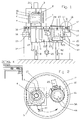
- FIGS 1 and 2 schematically show a first embodiment of an installation according to the invention with a treatment oven for a maximum temperature of 1100 ° C and two tanks mounted on a rotary table.
- This installation allows for example austenitization treatment, annealing, tempering, sintering or soldering.
- the oven 1 includes a heating chamber 2 with a turbine circulation of atmospheres 3, a plug 4 as support for the load to be treated 5 and two tanks, that is to say. of them loading or cooling chambers 6 and 7.
- the plug load carrier is moved vertically by both lifting pistons 8 and 9, as indicated by the two double arrows. These lifting pistons are designed for loading or unloading of loads in the oven or in the bins, as will emerge from the description of a cycle of work with this facility.
- the oven further includes a heating body 10 and a double insulated jacket 11 according to the art of known technique.
- the oven 1 is fixed on an upper table 12 while the tanks, i.e. the loading chambers or cooling 6 and 7 with the lifting pistons 8 and 9 are fixed to a rotary table 13.
- the fixed table 12 is mounted on a support 14.
- the rotary table 13 is driven in rotation by a motor 15.
- Between the fixed table and the rotary table there are two sets of seals, one seal exterior 16 to establish gas and vacuum tightness and two interior seals 17 and 18, which form a first sealing barrier between the tanks and the fixed table superior. All seals are inflatable seals, known per se in the prior art, and are partially deflated in case the rotary table is put in rotation, and then inflated to seal.
- Each loading or cooling chamber 6 and 7 includes an atmospheric circulation turbine 19 and 20, a common vacuum pump 21 which is connected by valves 22 and 23 to said loading chambers or cooling.
- Each tank 6 and 7 includes a supply 24 and 25 with nitrogen and the furnace includes a gas supply 26.
- the upper table includes a door 27 which has a joint 28 and which allows the introduction of the load into a bins.
- Nitrogen filling for example or another gas allows the charge to be treated to be transferred to the oven under protective gas or under vacuum.
- the remaining oven always at temperature allows one of the treatments to be carried out cited above.
- the charge is discharged in one of the two chambers for cooling. Before the rotation for transfer and cooling, we will have prepared a new load to be treated in the free bin of any charge. It is thus possible to treat, by alternation, parts without surface oxidation and without furnace cooling as well as without gas pollution from treatment or vacuum from the oven.
- bins that is to say. rooms of gas / gas loading / unloading or cooling the oil fixed to the support and to the upper table and provide one or more rotary oven (s).
- Figures 3A - 3L schematically show a cycle of job.
- Figure 3A shows the preparation of charge 5 and we see that door 27 is open.
- Figure B shows the conditioning of the load by vacuum and figure C lowering the left plug 4 to open the oven.
- the figure D shows the rotation of the tanks to load 5 under the oven, before its introduction into it (figure E), to start the treatment cycle.
- Figure F shows the preparation of a second 5A charge during the cycle of treatment of the first, and Figure G the conditioning of this charge 5A by vacuum.
- Figure H shows opening the oven and lowering the load 5, and figure I the rotation of the tanks with immediate cooling of the load 5.
- Figure K shows the introduction of the load 5A in the oven to complete the treatment cycle while the load is cooling 5.
- the figure L shows the load 5A during the treatment cycle in course and evacuation of charge 5, as well as setting place of a new charge 5B.
- This cycle of operations shows the great advantage of this installation according to the invention allowing on the one hand prepare one load while the other is in the oven and, above all, to bring and evacuate the load from the oven without vacuum or gas pollution in the oven and without oxidation charges. All the operations described are carried out tightly to the outside by the seal outer 16 is the inner seals 17 and 18.
- FIGS 4 and 5 show a second embodiment of the installation according to the invention with an oven and three bins.
- Oven 29 is similar to oven 1 in the example previous with the same elements such as bedroom heater, turbine, plug 4 which supports the load 5.
- the fixed upper table system 12 and its support 14 are also the same as in the previous example, while the rotary table 30 is arranged to carry three tubs and includes three interior gasket packings 31, 32 and 33.
- the outer seal 16 is similar to that of the execution described above as well as door 27 with its attached 28.
- the first tank is a loading chamber 34, similar to room 6, the second tank is a gas cooling 35 and the third tank is a cooling chamber with liquid 36, for example oil 37.
- the loading chamber and the gas cooling include turbines 38 and 39 while the oil-cooled chamber includes an oil pump 40 for the circulation of the oil.
- This installation also includes a vacuum pump with valves to be able to evacuate the loading and gas cooling, as well as gas supplies for the rooms and for the oven.
- Each room includes in addition to a lifting piston 41, resp. 42, resp. 43.
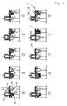
- FIGS. 6A to 6K An example of a work cycle with this installation is described using FIGS. 6A to 6K.
- Figure 6A shows the preparation of charge 5 above the load 34 with door 27 open.
- Figure 6B shows conditioning of the charge, possibly by vacuum, with door 27 closed and figure C shows the situation after the rotation of the chambers with a 120 ° stroke for bring the load 5 under the oven.
- Figure D the charge is introduced into the furnace and the treatment cycle in the oven begins.
- the plugs are upgraded with rotary table after treatment thermal to perform a rotation shown in Figure F. During this rotation, the load slides on the table and afterwards, the oil chamber is under the load, i.e. under the oven.
- Figure G shows the descent of the charging and immediate cooling thereof in oil.
- FIG H we see the preparation of the second load 5A, this possibly being conditioned by the vacuum, as well as the cooling of the first charge 5 in oil.
- Figure I shows a new rotation of the chambers to bring the second load 5A under the oven before introducing it.
- Figure 6K finally shows the situation where the processing cycle is performed for the second charge 5A while the first charge 5 is discharged, to return to the situation of the Figure 6E.
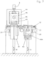
- Figure 7 shows a third example of execution of a installation according to the invention with a vacuum oven 44 to hot wall with graphite 45 heating, insulation 46, a circulation turbine 3 for the bass processing temperatures and plugs 49, 49A supporting the load 5.
- the upper fixed table system 12 with its door 27 and seal 28, the rotary table 13 driven by the motor 15 and the two seal systems with outer seal 16 and inner seals 17 and 18, east the same as before.
- Bins hanging from the table rotary are two loading and unloading chambers 47 and 48 with incorporated cooler, comprising both turbines 19 and 20 according to the first embodiment.
- FIGS. 8A to 8L illustrating an example of a cycle of work done by the installation of figure 7.
- the figure 8A shows the preparation of load 5 with the door open and Figure 8B shows the packaging of the charge by vacuum.
- Figure C shows the descent of the plug 49 and the opening of the oven followed by the rotation of chambers according to figure D in order to bring the load 5 under the oven.
- Figure E shows the introduction of the charge into the oven initiating the treatment cycle.
- the second charge 5A is prepared and conditioned by vacuum according to figure G.
- Figure H shows the opening of the oven and the descent of the first load followed by a rotation of the chambers with immediate cooling of the first charge in the cooling chamber 47 (FIG.
- Figure 8L shows that while the second charge is being treatment, the first charge is discharged and the third charge 5B is amended on the cap, to be then conditioned and treated.
- the same treatment cycle can apply to a installation where, as a variant, the vacuum oven has a cold wall and graphite insulation.
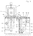
- Figure 9 shows a variant of the installation according to the Figure 7 with an oven 50 similar to the previous oven but additionally having four mechanical stops 51 with their commands 52 to hold or release the load 5A, such as this will emerge from the description according to FIGS. 10A to 10L.
- the upper fixed table 12 is similar to the previous case with the door 27 and its seals 28 as well as the support of the table 14. Between the fixed table 12 and the rotary table 13 is finds the same joint system as described above and the rotary table is driven by the motor 15. At the table are suspended at least one oil chamber 53 with its pump system 40 and at least one tank of gas cooling 54 with the turbine 20.
- the tank 54 is a pressure chamber and that is why the lift piston provided for the other tanks is here replaced by a lift 55 including a load support 56, linked to a supporting column 57 with a screw 58 which is rotated by a motor 59 with transmission by chain, to raise or lower the elevator. All the elevator device is located within the compound of the pressure chamber. Upward, the pressure chamber is closed by a lower door 60, seals 61 sealing. The loading and unloading of parts can be done by this pressure chamber, or else the installation includes, in addition to this pressure chamber and from the oil chamber, a loading chamber described in the previous examples.
- FIGS. 10A to 10L schematically show a cycle of possible treatment with the installation of figure 9.
- the Figure 10A shows the preparation of charge 5, always with the door open, and Figure 10B the packaging load by vacuum, with door 27 closed, followed by the rotation of the chambers to put the load under the oven ( Figure 10C).
- Figure D the charge is introduced into the oven to start the treatment cycle and, at the end of the cycle in FIG. E, the load is lowered and the hooks 51 are closed to retain it during the lowering of the stopper by the elevator 55.
- the chambers are rotated to bring the chamber to oil under the oven and, according to G, the load carrier is mounted and the hooks are open.
- the load on the support load is lowered to be immersed in oil (figure H) for immediate cooling, intensified by a forced flow channel in the oil chamber.
- the second load 5A is prepared and conditioned by vacuum, then rotated according to Figure K to bring it under the oven for a treatment cycle according to the figure L, while the first load is discharged after draining to chain a new cycle from situation shown in figure D.
- Figure 11 shows another embodiment of a the installation according to the invention with a similar oven 62 in oven 29 of FIG. 4, but additionally comprising two half-drawers 63 and 63A, forming the cap, which are controlled by mechanical elements 64.
- Everything is fixed on the upper fixed table 12 which is similar to that from previous executions and attached to the supports 14.
- Under the fixed table is a rotary table similar to that from previous versions, with the two joint systems exterior and interior.
- the bins, i.e. the room oil and the cooling chamber (s) are same as in the execution according to figure 4.
- Figures 12A to 12P show a work cycle with installation according to figure 11 and will make better understand the role of the two half-drawers 63, 63A.
- Figure 12 A shows the preparation of load 5
- Figure B its vacuum conditioning
- figure C the rotation of chambers for placing said charge under the oven.
- the half-drawers are moved to open the oven, before the charge is introduced into it and that the half drawers are slightly closed, like this spring of figure E.
- the load support 56 is lowered to deposit the load on the plug 63, 63A.
- the oven is closed and the treatment cycle start. During this time, the rooms are put in rotation and the oil pan is brought under the oven and simultaneously according to I the second charge 5A is prepared and conditioned by vacuum.
- the plug which has the form of two half-drawers 63 and 63A is not moved vertically, as in the first executions, but is pulled or pushed horizontally.
- FIGS 13 and 14 schematically show a variant of execution with, for example an oven and four bins hanging on the rotary table.
- the oven can be the kind of one of the ovens described above, while two bins are provided for loading / unloading and two bins for cooling, either by gas or by liquid, for example oil. All combinations are possible, i.e. that the number and kind of ovens nor the number and kind of containers is in principle limited in an installation according to the invention.
- the executions disclosed in Figures 1 to 14 are installations with a fixed table and a rotary table including seals.
- the oven (s) are attached to the fixed table and the hanging trays connected to the rotary table.
- a reverse assembly that is to say according to which the oven (s) are integral with the rotary table and where the bins are suspended from a table fixed, is also possible.
- the tightness between the fixed table and the rotary table is ensured by an inflatable external seal and seals, depending on the number of trays, interior inflatable, all ensuring perfect sealing of so as to allow processing of parts, on the one hand, without surface oxidation and pollution-free treatment gases of the oven or without pollution of the oven vacuum and, on the other hand, without cooling the oven during operations.
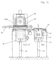
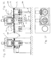
- FIGS 15 to 17 show a first embodiment of such a linear displacement installation with an oven and two bins.
- the oven corresponds to oven 1 of the execution according to Figure 1, with the same elements, such as room heater, turbine and plug, this oven being fixed on a upper table 65 supported by a support 66.
- a translation table 67 is located below the upper table, the translation table carrying two tanks 68 and 69 arranged in loading chambers and cooling and each provided with a piston elevator 8 and 9 and gas supply and connected to a pump vacuum to evacuate the rooms.
- an outer seal 70 and two inner seals 71 and 72 are provided, these seals being inflatable like the others joints mentioned above.
- the linear solution requires, as shown in Figure 16, two watertight loading doors 73 and 74.
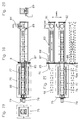
- Figures 18 to 21 show an oven installation growing at long load.
- the load can be for example a load composed of 6 m long tubes, to be annealed under vacuum or under atmosphere, and it is obvious that the reduction significant of the total length of such an installation where the oven must have the same length, has an advantage considerable.
- the oven 75 of the push type with a long charge is known per se and includes a sealed channel or carcass 76 and a heating chamber 77 and a circulation turbine atmospheres 78 and a gas supply 79, the whole being arranged in an enclosure 80.
- Each of the two bedrooms loading / unloading 81, 82 is provided with a cooler 83 and a gas circulation turbine 84.
- the installation also includes a fixed plate 85 integral with the oven and equipped with two loading doors 86 or unloading baskets or other objects, such as tubes. These doors are fitted with gaskets.
- the rooms loading or unloading are integral with a plate mobile 87 mounted on slide. Sealing is ensured by a seal 88 around each loading chamber, these seals being inflatable like the previous seals.
- Each loading or unloading chamber includes a system 89 for introduction and extraction of load 90 in the cooling channel and in the oven.
- a vacuum pump allows extraction of chamber in gas loading or unloading position or oxygen. In this way, no trace of oxidation or air pollution is possible.
- the arrangement of the elements of the installation allows reduce the overall dimensions by one or two load lengths of the installation and above all, not to immobilize the loading chamber during cooling of the charge. This is clear if we compare this installation according to the invention with the installations known until now and sold by different houses.
Landscapes
- Chemical & Material Sciences (AREA)
- Engineering & Computer Science (AREA)
- Mechanical Engineering (AREA)
- Crystallography & Structural Chemistry (AREA)
- Thermal Sciences (AREA)
- Physics & Mathematics (AREA)
- Materials Engineering (AREA)
- Metallurgy (AREA)
- Organic Chemistry (AREA)
- General Engineering & Computer Science (AREA)
- Furnace Details (AREA)
- Physical Or Chemical Processes And Apparatus (AREA)
- Heat Treatments In General, Especially Conveying And Cooling (AREA)
- Furnace Charging Or Discharging (AREA)
Priority Applications (4)
| Application Number | Priority Date | Filing Date | Title |
|---|---|---|---|
| ES98811062T ES2199416T3 (es) | 1998-10-23 | 1998-10-23 | Instalacion para el tratamiento termico de una carga de piezas metalicas. |
| DE69815108T DE69815108T2 (de) | 1998-10-23 | 1998-10-23 | Wärmebehandlungsanlage für eine Charge metallischer Werkstücke |
| EP98811062A EP0995805B9 (de) | 1998-10-23 | 1998-10-23 | Wärmebehandlungsanlage für eine Charge metallischer Werkstücke |
| AT98811062T ATE241705T1 (de) | 1998-10-23 | 1998-10-23 | Wärmebehandlungsanlage für eine charge metallischer werkstücke |
Applications Claiming Priority (1)
| Application Number | Priority Date | Filing Date | Title |
|---|---|---|---|
| EP98811062A EP0995805B9 (de) | 1998-10-23 | 1998-10-23 | Wärmebehandlungsanlage für eine Charge metallischer Werkstücke |
Publications (3)
| Publication Number | Publication Date |
|---|---|
| EP0995805A1 true EP0995805A1 (de) | 2000-04-26 |
| EP0995805B1 EP0995805B1 (de) | 2003-05-28 |
| EP0995805B9 EP0995805B9 (de) | 2004-01-28 |
Family
ID=8236401
Family Applications (1)
| Application Number | Title | Priority Date | Filing Date |
|---|---|---|---|
| EP98811062A Expired - Lifetime EP0995805B9 (de) | 1998-10-23 | 1998-10-23 | Wärmebehandlungsanlage für eine Charge metallischer Werkstücke |
Country Status (4)
| Country | Link |
|---|---|
| EP (1) | EP0995805B9 (de) |
| AT (1) | ATE241705T1 (de) |
| DE (1) | DE69815108T2 (de) |
| ES (1) | ES2199416T3 (de) |
Cited By (30)
| Publication number | Priority date | Publication date | Assignee | Title |
|---|---|---|---|---|
| US7583990B2 (en) | 2003-08-01 | 2009-09-01 | Dexcom, Inc. | System and methods for processing analyte sensor data |
| US7774145B2 (en) | 2003-08-01 | 2010-08-10 | Dexcom, Inc. | Transcutaneous analyte sensor |
| US8275437B2 (en) | 2003-08-01 | 2012-09-25 | Dexcom, Inc. | Transcutaneous analyte sensor |
| US9610031B2 (en) | 2004-07-13 | 2017-04-04 | Dexcom, Inc. | Transcutaneous analyte sensor |
| US9610034B2 (en) | 2001-01-02 | 2017-04-04 | Abbott Diabetes Care Inc. | Analyte monitoring device and methods of use |
| US9649069B2 (en) | 2003-08-22 | 2017-05-16 | Dexcom, Inc. | Systems and methods for replacing signal artifacts in a glucose sensor data stream |
| US9750441B2 (en) | 2003-12-09 | 2017-09-05 | Dexcom, Inc. | Signal processing for continuous analyte sensor |
| US9804114B2 (en) | 2001-07-27 | 2017-10-31 | Dexcom, Inc. | Sensor head for use with implantable devices |
| US9833143B2 (en) | 2004-05-03 | 2017-12-05 | Dexcom, Inc. | Transcutaneous analyte sensor |
| US9895089B2 (en) | 2003-08-01 | 2018-02-20 | Dexcom, Inc. | System and methods for processing analyte sensor data |
| US9986942B2 (en) | 2004-07-13 | 2018-06-05 | Dexcom, Inc. | Analyte sensor |
| US10201301B2 (en) | 2005-11-01 | 2019-02-12 | Abbott Diabetes Care Inc. | Analyte monitoring device and methods of use |
| US10231654B2 (en) | 2005-11-01 | 2019-03-19 | Abbott Diabetes Care Inc. | Analyte monitoring device and methods of use |
| US10349873B2 (en) | 2006-10-04 | 2019-07-16 | Dexcom, Inc. | Analyte sensor |
| US10478108B2 (en) | 1998-04-30 | 2019-11-19 | Abbott Diabetes Care Inc. | Analyte monitoring device and methods of use |
| US10610136B2 (en) | 2005-03-10 | 2020-04-07 | Dexcom, Inc. | System and methods for processing analyte sensor data for sensor calibration |
| US10653835B2 (en) | 2007-10-09 | 2020-05-19 | Dexcom, Inc. | Integrated insulin delivery system with continuous glucose sensor |
| US10813577B2 (en) | 2005-06-21 | 2020-10-27 | Dexcom, Inc. | Analyte sensor |
| US10966609B2 (en) | 2004-02-26 | 2021-04-06 | Dexcom, Inc. | Integrated medicament delivery device for use with continuous analyte sensor |
| US10980461B2 (en) | 2008-11-07 | 2021-04-20 | Dexcom, Inc. | Advanced analyte sensor calibration and error detection |
| US11000215B1 (en) | 2003-12-05 | 2021-05-11 | Dexcom, Inc. | Analyte sensor |
| US11102306B2 (en) | 2008-02-21 | 2021-08-24 | Dexcom, Inc. | Systems and methods for processing, transmitting and displaying sensor data |
| US11246990B2 (en) | 2004-02-26 | 2022-02-15 | Dexcom, Inc. | Integrated delivery device for continuous glucose sensor |
| US11331022B2 (en) | 2017-10-24 | 2022-05-17 | Dexcom, Inc. | Pre-connected analyte sensors |
| US11350862B2 (en) | 2017-10-24 | 2022-06-07 | Dexcom, Inc. | Pre-connected analyte sensors |
| US11373347B2 (en) | 2007-06-08 | 2022-06-28 | Dexcom, Inc. | Integrated medicament delivery device for use with continuous analyte sensor |
| US11382539B2 (en) | 2006-10-04 | 2022-07-12 | Dexcom, Inc. | Analyte sensor |
| US11432772B2 (en) | 2006-08-02 | 2022-09-06 | Dexcom, Inc. | Systems and methods for replacing signal artifacts in a glucose sensor data stream |
| US11559260B2 (en) | 2003-08-22 | 2023-01-24 | Dexcom, Inc. | Systems and methods for processing analyte sensor data |
| US11564602B2 (en) | 2003-11-19 | 2023-01-31 | Dexcom, Inc. | Integrated receiver for continuous analyte sensor |
Families Citing this family (17)
| Publication number | Priority date | Publication date | Assignee | Title |
|---|---|---|---|---|
| US6175752B1 (en) | 1998-04-30 | 2001-01-16 | Therasense, Inc. | Analyte monitoring device and methods of use |
| US6949816B2 (en) | 2003-04-21 | 2005-09-27 | Motorola, Inc. | Semiconductor component having first surface area for electrically coupling to a semiconductor chip and second surface area for electrically coupling to a substrate, and method of manufacturing same |
| US8346337B2 (en) | 1998-04-30 | 2013-01-01 | Abbott Diabetes Care Inc. | Analyte monitoring device and methods of use |
| US9066695B2 (en) | 1998-04-30 | 2015-06-30 | Abbott Diabetes Care Inc. | Analyte monitoring device and methods of use |
| US8465425B2 (en) | 1998-04-30 | 2013-06-18 | Abbott Diabetes Care Inc. | Analyte monitoring device and methods of use |
| US9247901B2 (en) | 2003-08-22 | 2016-02-02 | Dexcom, Inc. | Systems and methods for replacing signal artifacts in a glucose sensor data stream |
| US9282925B2 (en) | 2002-02-12 | 2016-03-15 | Dexcom, Inc. | Systems and methods for replacing signal artifacts in a glucose sensor data stream |
| US8369919B2 (en) | 2003-08-01 | 2013-02-05 | Dexcom, Inc. | Systems and methods for processing sensor data |
| US8845536B2 (en) | 2003-08-01 | 2014-09-30 | Dexcom, Inc. | Transcutaneous analyte sensor |
| US7925321B2 (en) | 2003-08-01 | 2011-04-12 | Dexcom, Inc. | System and methods for processing analyte sensor data |
| US8886273B2 (en) | 2003-08-01 | 2014-11-11 | Dexcom, Inc. | Analyte sensor |
| US8160669B2 (en) | 2003-08-01 | 2012-04-17 | Dexcom, Inc. | Transcutaneous analyte sensor |
| US8233959B2 (en) | 2003-08-22 | 2012-07-31 | Dexcom, Inc. | Systems and methods for processing analyte sensor data |
| US7857760B2 (en) | 2004-07-13 | 2010-12-28 | Dexcom, Inc. | Analyte sensor |
| US8452368B2 (en) | 2004-07-13 | 2013-05-28 | Dexcom, Inc. | Transcutaneous analyte sensor |
| DE102014008767A1 (de) * | 2014-06-12 | 2015-12-17 | Audi Ag | Prozesssystem zur Bearbeitung eines Bauteils |
| CN112781377A (zh) * | 2020-07-31 | 2021-05-11 | 上海毅兴塑胶原料有限公司 | 一种动态热机械分析仪用加热炉快速冷却机构 |
Citations (7)
| Publication number | Priority date | Publication date | Assignee | Title |
|---|---|---|---|---|
| US2247770A (en) * | 1940-07-27 | 1941-07-01 | Gen Electric | Heat treating apparatus |
| EP0023546A1 (de) * | 1979-06-15 | 1981-02-11 | Dr. Werner Herdieckerhoff, Nachfolger Industrieöfen - Apparatebau | Verfahren und Vorrichtung zur Gefüge- und/oder Oberflächenveredelung von Metallen |
| EP0296102A1 (de) * | 1987-06-03 | 1988-12-21 | Pierre Beuret | Vorrichtung mit mehreren Einzelteilen für Wärmebehandlungen |
| EP0388333A1 (de) * | 1989-03-17 | 1990-09-19 | Etudes Et Constructions Mecaniques | Vorrichtung zu kontinuierlichen folgenden Vakuumwärmebehandlungen |
| EP0785402A1 (de) * | 1996-01-17 | 1997-07-23 | Pierre Beuret | Wärmebehandlungsanalage für eine Ladung aus metallischen Stücken |
| EP0806485A1 (de) * | 1996-05-06 | 1997-11-12 | Patherm SA | Wärmebehandlungsanlage |
| EP0893510A1 (de) * | 1997-07-21 | 1999-01-27 | Refrattari Brebbia S.r.l. | Selbsttätig arbeitende Wärmebehandlungsanlage für Metalle, insbesondere für Stähle |
-
1998
- 1998-10-23 ES ES98811062T patent/ES2199416T3/es not_active Expired - Lifetime
- 1998-10-23 EP EP98811062A patent/EP0995805B9/de not_active Expired - Lifetime
- 1998-10-23 AT AT98811062T patent/ATE241705T1/de active
- 1998-10-23 DE DE69815108T patent/DE69815108T2/de not_active Expired - Lifetime
Patent Citations (7)
| Publication number | Priority date | Publication date | Assignee | Title |
|---|---|---|---|---|
| US2247770A (en) * | 1940-07-27 | 1941-07-01 | Gen Electric | Heat treating apparatus |
| EP0023546A1 (de) * | 1979-06-15 | 1981-02-11 | Dr. Werner Herdieckerhoff, Nachfolger Industrieöfen - Apparatebau | Verfahren und Vorrichtung zur Gefüge- und/oder Oberflächenveredelung von Metallen |
| EP0296102A1 (de) * | 1987-06-03 | 1988-12-21 | Pierre Beuret | Vorrichtung mit mehreren Einzelteilen für Wärmebehandlungen |
| EP0388333A1 (de) * | 1989-03-17 | 1990-09-19 | Etudes Et Constructions Mecaniques | Vorrichtung zu kontinuierlichen folgenden Vakuumwärmebehandlungen |
| EP0785402A1 (de) * | 1996-01-17 | 1997-07-23 | Pierre Beuret | Wärmebehandlungsanalage für eine Ladung aus metallischen Stücken |
| EP0806485A1 (de) * | 1996-05-06 | 1997-11-12 | Patherm SA | Wärmebehandlungsanlage |
| EP0893510A1 (de) * | 1997-07-21 | 1999-01-27 | Refrattari Brebbia S.r.l. | Selbsttätig arbeitende Wärmebehandlungsanlage für Metalle, insbesondere für Stähle |
Cited By (96)
| Publication number | Priority date | Publication date | Assignee | Title |
|---|---|---|---|---|
| US10478108B2 (en) | 1998-04-30 | 2019-11-19 | Abbott Diabetes Care Inc. | Analyte monitoring device and methods of use |
| US9610034B2 (en) | 2001-01-02 | 2017-04-04 | Abbott Diabetes Care Inc. | Analyte monitoring device and methods of use |
| US9804114B2 (en) | 2001-07-27 | 2017-10-31 | Dexcom, Inc. | Sensor head for use with implantable devices |
| US7599726B2 (en) | 2003-08-01 | 2009-10-06 | Dexcom, Inc. | System and methods for processing analyte sensor data |
| US7774145B2 (en) | 2003-08-01 | 2010-08-10 | Dexcom, Inc. | Transcutaneous analyte sensor |
| US8275437B2 (en) | 2003-08-01 | 2012-09-25 | Dexcom, Inc. | Transcutaneous analyte sensor |
| US8986209B2 (en) | 2003-08-01 | 2015-03-24 | Dexcom, Inc. | Transcutaneous analyte sensor |
| US10786185B2 (en) | 2003-08-01 | 2020-09-29 | Dexcom, Inc. | System and methods for processing analyte sensor data |
| US9895089B2 (en) | 2003-08-01 | 2018-02-20 | Dexcom, Inc. | System and methods for processing analyte sensor data |
| US7583990B2 (en) | 2003-08-01 | 2009-09-01 | Dexcom, Inc. | System and methods for processing analyte sensor data |
| US9724045B1 (en) | 2003-08-22 | 2017-08-08 | Dexcom, Inc. | Systems and methods for replacing signal artifacts in a glucose sensor data stream |
| US11589823B2 (en) | 2003-08-22 | 2023-02-28 | Dexcom, Inc. | Systems and methods for replacing signal artifacts in a glucose sensor data stream |
| US11559260B2 (en) | 2003-08-22 | 2023-01-24 | Dexcom, Inc. | Systems and methods for processing analyte sensor data |
| US9750460B2 (en) | 2003-08-22 | 2017-09-05 | Dexcom, Inc. | Systems and methods for replacing signal artifacts in a glucose sensor data stream |
| US9649069B2 (en) | 2003-08-22 | 2017-05-16 | Dexcom, Inc. | Systems and methods for replacing signal artifacts in a glucose sensor data stream |
| US11564602B2 (en) | 2003-11-19 | 2023-01-31 | Dexcom, Inc. | Integrated receiver for continuous analyte sensor |
| US11020031B1 (en) | 2003-12-05 | 2021-06-01 | Dexcom, Inc. | Analyte sensor |
| US11000215B1 (en) | 2003-12-05 | 2021-05-11 | Dexcom, Inc. | Analyte sensor |
| US10898113B2 (en) | 2003-12-09 | 2021-01-26 | Dexcom, Inc. | Signal processing for continuous analyte sensor |
| US11638541B2 (en) | 2003-12-09 | 2023-05-02 | Dexconi, Inc. | Signal processing for continuous analyte sensor |
| US9750441B2 (en) | 2003-12-09 | 2017-09-05 | Dexcom, Inc. | Signal processing for continuous analyte sensor |
| US12115357B2 (en) | 2004-02-26 | 2024-10-15 | Dexcom, Inc. | Integrated delivery device for continuous glucose sensor |
| US10835672B2 (en) | 2004-02-26 | 2020-11-17 | Dexcom, Inc. | Integrated insulin delivery system with continuous glucose sensor |
| US12102410B2 (en) | 2004-02-26 | 2024-10-01 | Dexcom, Inc | Integrated medicament delivery device for use with continuous analyte sensor |
| US12226617B2 (en) | 2004-02-26 | 2025-02-18 | Dexcom, Inc. | Integrated delivery device for continuous glucose sensor |
| US11246990B2 (en) | 2004-02-26 | 2022-02-15 | Dexcom, Inc. | Integrated delivery device for continuous glucose sensor |
| US10966609B2 (en) | 2004-02-26 | 2021-04-06 | Dexcom, Inc. | Integrated medicament delivery device for use with continuous analyte sensor |
| US9833143B2 (en) | 2004-05-03 | 2017-12-05 | Dexcom, Inc. | Transcutaneous analyte sensor |
| US10327638B2 (en) | 2004-05-03 | 2019-06-25 | Dexcom, Inc. | Transcutaneous analyte sensor |
| US10827956B2 (en) | 2004-07-13 | 2020-11-10 | Dexcom, Inc. | Analyte sensor |
| US11026605B1 (en) | 2004-07-13 | 2021-06-08 | Dexcom, Inc. | Analyte sensor |
| US10722152B2 (en) | 2004-07-13 | 2020-07-28 | Dexcom, Inc. | Analyte sensor |
| US11064917B2 (en) | 2004-07-13 | 2021-07-20 | Dexcom, Inc. | Analyte sensor |
| US10524703B2 (en) | 2004-07-13 | 2020-01-07 | Dexcom, Inc. | Transcutaneous analyte sensor |
| US10799158B2 (en) | 2004-07-13 | 2020-10-13 | Dexcom, Inc. | Analyte sensor |
| US10799159B2 (en) | 2004-07-13 | 2020-10-13 | Dexcom, Inc. | Analyte sensor |
| US10813576B2 (en) | 2004-07-13 | 2020-10-27 | Dexcom, Inc. | Analyte sensor |
| US11045120B2 (en) | 2004-07-13 | 2021-06-29 | Dexcom, Inc. | Analyte sensor |
| US9986942B2 (en) | 2004-07-13 | 2018-06-05 | Dexcom, Inc. | Analyte sensor |
| US11883164B2 (en) | 2004-07-13 | 2024-01-30 | Dexcom, Inc. | System and methods for processing analyte sensor data for sensor calibration |
| US10709362B2 (en) | 2004-07-13 | 2020-07-14 | Dexcom, Inc. | Analyte sensor |
| US10709363B2 (en) | 2004-07-13 | 2020-07-14 | Dexcom, Inc. | Analyte sensor |
| US9814414B2 (en) | 2004-07-13 | 2017-11-14 | Dexcom, Inc. | Transcutaneous analyte sensor |
| US9610031B2 (en) | 2004-07-13 | 2017-04-04 | Dexcom, Inc. | Transcutaneous analyte sensor |
| US10993641B2 (en) | 2004-07-13 | 2021-05-04 | Dexcom, Inc. | Analyte sensor |
| US10918313B2 (en) | 2004-07-13 | 2021-02-16 | Dexcom, Inc. | Analyte sensor |
| US10993642B2 (en) | 2004-07-13 | 2021-05-04 | Dexcom, Inc. | Analyte sensor |
| US10918315B2 (en) | 2004-07-13 | 2021-02-16 | Dexcom, Inc. | Analyte sensor |
| US10918314B2 (en) | 2004-07-13 | 2021-02-16 | Dexcom, Inc. | Analyte sensor |
| US10980452B2 (en) | 2004-07-13 | 2021-04-20 | Dexcom, Inc. | Analyte sensor |
| US10932700B2 (en) | 2004-07-13 | 2021-03-02 | Dexcom, Inc. | Analyte sensor |
| US10610137B2 (en) | 2005-03-10 | 2020-04-07 | Dexcom, Inc. | System and methods for processing analyte sensor data for sensor calibration |
| US10716498B2 (en) | 2005-03-10 | 2020-07-21 | Dexcom, Inc. | System and methods for processing analyte sensor data for sensor calibration |
| US10925524B2 (en) | 2005-03-10 | 2021-02-23 | Dexcom, Inc. | System and methods for processing analyte sensor data for sensor calibration |
| US10610136B2 (en) | 2005-03-10 | 2020-04-07 | Dexcom, Inc. | System and methods for processing analyte sensor data for sensor calibration |
| US10918316B2 (en) | 2005-03-10 | 2021-02-16 | Dexcom, Inc. | System and methods for processing analyte sensor data for sensor calibration |
| US10918317B2 (en) | 2005-03-10 | 2021-02-16 | Dexcom, Inc. | System and methods for processing analyte sensor data for sensor calibration |
| US10918318B2 (en) | 2005-03-10 | 2021-02-16 | Dexcom, Inc. | System and methods for processing analyte sensor data for sensor calibration |
| US11000213B2 (en) | 2005-03-10 | 2021-05-11 | Dexcom, Inc. | System and methods for processing analyte sensor data for sensor calibration |
| US10898114B2 (en) | 2005-03-10 | 2021-01-26 | Dexcom, Inc. | System and methods for processing analyte sensor data for sensor calibration |
| US10856787B2 (en) | 2005-03-10 | 2020-12-08 | Dexcom, Inc. | System and methods for processing analyte sensor data for sensor calibration |
| US10610135B2 (en) | 2005-03-10 | 2020-04-07 | Dexcom, Inc. | System and methods for processing analyte sensor data for sensor calibration |
| US11051726B2 (en) | 2005-03-10 | 2021-07-06 | Dexcom, Inc. | System and methods for processing analyte sensor data for sensor calibration |
| US10743801B2 (en) | 2005-03-10 | 2020-08-18 | Dexcom, Inc. | System and methods for processing analyte sensor data for sensor calibration |
| US10617336B2 (en) | 2005-03-10 | 2020-04-14 | Dexcom, Inc. | System and methods for processing analyte sensor data for sensor calibration |
| US10709364B2 (en) | 2005-03-10 | 2020-07-14 | Dexcom, Inc. | System and methods for processing analyte sensor data for sensor calibration |
| US10813577B2 (en) | 2005-06-21 | 2020-10-27 | Dexcom, Inc. | Analyte sensor |
| US11911151B1 (en) | 2005-11-01 | 2024-02-27 | Abbott Diabetes Care Inc. | Analyte monitoring device and methods of use |
| US11272867B2 (en) | 2005-11-01 | 2022-03-15 | Abbott Diabetes Care Inc. | Analyte monitoring device and methods of use |
| US10201301B2 (en) | 2005-11-01 | 2019-02-12 | Abbott Diabetes Care Inc. | Analyte monitoring device and methods of use |
| US10231654B2 (en) | 2005-11-01 | 2019-03-19 | Abbott Diabetes Care Inc. | Analyte monitoring device and methods of use |
| US11363975B2 (en) | 2005-11-01 | 2022-06-21 | Abbott Diabetes Care Inc. | Analyte monitoring device and methods of use |
| US10952652B2 (en) | 2005-11-01 | 2021-03-23 | Abbott Diabetes Care Inc. | Analyte monitoring device and methods of use |
| US11399748B2 (en) | 2005-11-01 | 2022-08-02 | Abbott Diabetes Care Inc. | Analyte monitoring device and methods of use |
| US11103165B2 (en) | 2005-11-01 | 2021-08-31 | Abbott Diabetes Care Inc. | Analyte monitoring device and methods of use |
| US11432772B2 (en) | 2006-08-02 | 2022-09-06 | Dexcom, Inc. | Systems and methods for replacing signal artifacts in a glucose sensor data stream |
| US10349873B2 (en) | 2006-10-04 | 2019-07-16 | Dexcom, Inc. | Analyte sensor |
| US11382539B2 (en) | 2006-10-04 | 2022-07-12 | Dexcom, Inc. | Analyte sensor |
| US11373347B2 (en) | 2007-06-08 | 2022-06-28 | Dexcom, Inc. | Integrated medicament delivery device for use with continuous analyte sensor |
| US12456239B2 (en) | 2007-06-08 | 2025-10-28 | Dexcom, Inc. | Integrated medicament delivery device for use with continuous analyte sensor |
| US12394120B2 (en) | 2007-06-08 | 2025-08-19 | Dexcom, Inc. | Integrated medicament delivery device for use with continuous analyte sensor |
| US12536716B2 (en) | 2007-06-08 | 2026-01-27 | Dexcom, Inc. | Integrated medicament delivery device for use with continuous analyte sensor |
| US12246166B2 (en) | 2007-10-09 | 2025-03-11 | Dexcom, Inc. | Integrated insulin delivery system with continuous glucose sensor |
| US12397110B2 (en) | 2007-10-09 | 2025-08-26 | Dexcom, Inc. | Integrated insulin delivery system with continuous glucose sensor |
| US11744943B2 (en) | 2007-10-09 | 2023-09-05 | Dexcom, Inc. | Integrated insulin delivery system with continuous glucose sensor |
| US10653835B2 (en) | 2007-10-09 | 2020-05-19 | Dexcom, Inc. | Integrated insulin delivery system with continuous glucose sensor |
| US12397113B2 (en) | 2007-10-09 | 2025-08-26 | Dexcom, Inc. | Integrated insulin delivery system with continuous glucose sensor |
| US11160926B1 (en) | 2007-10-09 | 2021-11-02 | Dexcom, Inc. | Pre-connected analyte sensors |
| US11102306B2 (en) | 2008-02-21 | 2021-08-24 | Dexcom, Inc. | Systems and methods for processing, transmitting and displaying sensor data |
| US10980461B2 (en) | 2008-11-07 | 2021-04-20 | Dexcom, Inc. | Advanced analyte sensor calibration and error detection |
| US11382540B2 (en) | 2017-10-24 | 2022-07-12 | Dexcom, Inc. | Pre-connected analyte sensors |
| US12150250B2 (en) | 2017-10-24 | 2024-11-19 | Dexcom, Inc. | Pre-connected analyte sensors |
| US11943876B2 (en) | 2017-10-24 | 2024-03-26 | Dexcom, Inc. | Pre-connected analyte sensors |
| US11706876B2 (en) | 2017-10-24 | 2023-07-18 | Dexcom, Inc. | Pre-connected analyte sensors |
| US11350862B2 (en) | 2017-10-24 | 2022-06-07 | Dexcom, Inc. | Pre-connected analyte sensors |
| US11331022B2 (en) | 2017-10-24 | 2022-05-17 | Dexcom, Inc. | Pre-connected analyte sensors |
Also Published As
| Publication number | Publication date |
|---|---|
| EP0995805B1 (de) | 2003-05-28 |
| DE69815108D1 (de) | 2003-07-03 |
| DE69815108T2 (de) | 2004-02-05 |
| ATE241705T1 (de) | 2003-06-15 |
| EP0995805B9 (de) | 2004-01-28 |
| ES2199416T3 (es) | 2004-02-16 |
Similar Documents
| Publication | Publication Date | Title |
|---|---|---|
| EP0995805B1 (de) | Wärmebehandlungsanlage für eine Charge metallischer Werkstücke | |
| JP3190165B2 (ja) | 縦型熱処理装置及び熱処理方法 | |
| RU2004126943A (ru) | Вакуумная печь для пайки давлением и способ ее использования | |
| WO2005090616A1 (ja) | 2室型熱処理炉 | |
| EP0388333B1 (de) | Vorrichtung zu kontinuierlichen folgenden Vakuumwärmebehandlungen | |
| EP0236639B1 (de) | Automatische flexible Vorrichtung für die Durchführung schneller thermochemischer Behandlungen | |
| FR2865135A1 (fr) | Installation de sterilisation d'articles par bombardement electronique | |
| FR2604378A1 (fr) | Appareillage de fonderie pour la fabrication de pieces metalliques moulees a structure orientee | |
| EP0533615B1 (de) | Wärmebehandlungsanlage für aufeinanderfolgende Chargen | |
| EP0309354B1 (de) | Automatische Vorrichtung für die schnelle thermochemische Behandlung | |
| FR2537260A1 (fr) | Four multicellulaire pour le traitement thermique, thermochimique ou electrothermique de metaux sous atmosphere rarefiee | |
| JP3894405B2 (ja) | 真空熱処理装置 | |
| EP0093060B1 (de) | Drehherdofen zur thermischen, thermochemischen oder elektrothermischen Behandlung von Metallen in verdünnter Atmosphäre | |
| RU2135339C1 (ru) | Способ изготовления металлической структуры | |
| EP0785402B1 (de) | Wärmebehandlungsanlage für eine Ladung aus metallischen Stücken | |
| CN222182364U (zh) | 一种安全高效的真空退火炉 | |
| FR2760524A1 (fr) | Four tournant etanche pour le sechage ou le traitement thermique de produits organiques | |
| JP2003130548A (ja) | ロータリーレトルト炉 | |
| CN216924951U (zh) | 一种可关闭被处理容器阀门的真空烘烤装置 | |
| JPH0345117Y2 (de) | ||
| CN221325082U (zh) | 一种加热均匀的加热炉 | |
| JPH0453927B2 (de) | ||
| FR2689225A1 (fr) | Four pour traitement sous vide ou sous atmosphère gazeuse et pour trempe sous pression. | |
| EP0219482B1 (de) | Haubenofen | |
| JPS627801A (ja) | 熱間静水圧加圧装置 |
Legal Events
| Date | Code | Title | Description |
|---|---|---|---|
| PUAI | Public reference made under article 153(3) epc to a published international application that has entered the european phase |
Free format text: ORIGINAL CODE: 0009012 |
|
| AK | Designated contracting states |
Kind code of ref document: A1 Designated state(s): AT CH DE ES FR GB IT LI |
|
| AX | Request for extension of the european patent |
Free format text: AL;LT;LV;MK;RO;SI |
|
| 17P | Request for examination filed |
Effective date: 20000510 |
|
| AKX | Designation fees paid |
Free format text: AT CH DE ES FR GB IT LI |
|
| 17Q | First examination report despatched |
Effective date: 20010705 |
|
| GRAH | Despatch of communication of intention to grant a patent |
Free format text: ORIGINAL CODE: EPIDOS IGRA |
|
| GRAH | Despatch of communication of intention to grant a patent |
Free format text: ORIGINAL CODE: EPIDOS IGRA |
|
| GRAA | (expected) grant |
Free format text: ORIGINAL CODE: 0009210 |
|
| AK | Designated contracting states |
Designated state(s): AT CH DE ES FR GB IT LI |
|
| REG | Reference to a national code |
Ref country code: GB Ref legal event code: FG4D Free format text: NOT ENGLISH |
|
| REG | Reference to a national code |
Ref country code: CH Ref legal event code: NV Representative=s name: AMMANN PATENTANWAELTE AG BERN Ref country code: CH Ref legal event code: EP |
|
| REF | Corresponds to: |
Ref document number: 69815108 Country of ref document: DE Date of ref document: 20030703 Kind code of ref document: P |
|
| GBT | Gb: translation of ep patent filed (gb section 77(6)(a)/1977) | ||
| REG | Reference to a national code |
Ref country code: ES Ref legal event code: FG2A Ref document number: 2199416 Country of ref document: ES Kind code of ref document: T3 |
|
| PLBE | No opposition filed within time limit |
Free format text: ORIGINAL CODE: 0009261 |
|
| STAA | Information on the status of an ep patent application or granted ep patent |
Free format text: STATUS: NO OPPOSITION FILED WITHIN TIME LIMIT |
|
| 26N | No opposition filed |
Effective date: 20040302 |
|
| PGFP | Annual fee paid to national office [announced via postgrant information from national office to epo] |
Ref country code: AT Payment date: 20101014 Year of fee payment: 13 |
|
| PGFP | Annual fee paid to national office [announced via postgrant information from national office to epo] |
Ref country code: GB Payment date: 20101021 Year of fee payment: 13 |
|
| GBPC | Gb: european patent ceased through non-payment of renewal fee |
Effective date: 20111023 |
|
| PG25 | Lapsed in a contracting state [announced via postgrant information from national office to epo] |
Ref country code: GB Free format text: LAPSE BECAUSE OF NON-PAYMENT OF DUE FEES Effective date: 20111023 |
|
| REG | Reference to a national code |
Ref country code: AT Ref legal event code: MM01 Ref document number: 241705 Country of ref document: AT Kind code of ref document: T Effective date: 20111023 |
|
| PG25 | Lapsed in a contracting state [announced via postgrant information from national office to epo] |
Ref country code: AT Free format text: LAPSE BECAUSE OF NON-PAYMENT OF DUE FEES Effective date: 20111023 |
|
| PGFP | Annual fee paid to national office [announced via postgrant information from national office to epo] |
Ref country code: FR Payment date: 20131022 Year of fee payment: 16 Ref country code: DE Payment date: 20131021 Year of fee payment: 16 Ref country code: CH Payment date: 20131023 Year of fee payment: 16 |
|
| PGFP | Annual fee paid to national office [announced via postgrant information from national office to epo] |
Ref country code: IT Payment date: 20131023 Year of fee payment: 16 Ref country code: ES Payment date: 20131029 Year of fee payment: 16 |
|
| REG | Reference to a national code |
Ref country code: DE Ref legal event code: R119 Ref document number: 69815108 Country of ref document: DE |
|
| REG | Reference to a national code |
Ref country code: CH Ref legal event code: PL |
|
| PG25 | Lapsed in a contracting state [announced via postgrant information from national office to epo] |
Ref country code: CH Free format text: LAPSE BECAUSE OF NON-PAYMENT OF DUE FEES Effective date: 20141031 Ref country code: LI Free format text: LAPSE BECAUSE OF NON-PAYMENT OF DUE FEES Effective date: 20141031 Ref country code: DE Free format text: LAPSE BECAUSE OF NON-PAYMENT OF DUE FEES Effective date: 20150501 |
|
| REG | Reference to a national code |
Ref country code: FR Ref legal event code: ST Effective date: 20150630 |
|
| PG25 | Lapsed in a contracting state [announced via postgrant information from national office to epo] |
Ref country code: IT Free format text: LAPSE BECAUSE OF NON-PAYMENT OF DUE FEES Effective date: 20141023 Ref country code: FR Free format text: LAPSE BECAUSE OF NON-PAYMENT OF DUE FEES Effective date: 20141031 |
|
| REG | Reference to a national code |
Ref country code: ES Ref legal event code: FD2A Effective date: 20151127 |
|
| PG25 | Lapsed in a contracting state [announced via postgrant information from national office to epo] |
Ref country code: ES Free format text: LAPSE BECAUSE OF NON-PAYMENT OF DUE FEES Effective date: 20141024 |