EP0995837B1 - Zweiteilige Schienenklammer und Werkzeug für ihre Befestigung - Google Patents
Zweiteilige Schienenklammer und Werkzeug für ihre Befestigung Download PDFInfo
- Publication number
- EP0995837B1 EP0995837B1 EP99308315A EP99308315A EP0995837B1 EP 0995837 B1 EP0995837 B1 EP 0995837B1 EP 99308315 A EP99308315 A EP 99308315A EP 99308315 A EP99308315 A EP 99308315A EP 0995837 B1 EP0995837 B1 EP 0995837B1
- Authority
- EP
- European Patent Office
- Prior art keywords
- clip member
- arm
- rail
- tool
- clip
- Prior art date
- Legal status (The legal status is an assumption and is not a legal conclusion. Google has not performed a legal analysis and makes no representation as to the accuracy of the status listed.)
- Expired - Lifetime
Links
- 238000000034 method Methods 0.000 claims description 7
- 238000013016 damping Methods 0.000 claims 1
- 230000006835 compression Effects 0.000 description 3
- 238000007906 compression Methods 0.000 description 3
- 238000010276 construction Methods 0.000 description 3
- 229910001209 Low-carbon steel Inorganic materials 0.000 description 2
- 229910000639 Spring steel Inorganic materials 0.000 description 1
- 229910000831 Steel Inorganic materials 0.000 description 1
- 239000010426 asphalt Substances 0.000 description 1
- 230000009286 beneficial effect Effects 0.000 description 1
- 230000015556 catabolic process Effects 0.000 description 1
- 238000006731 degradation reaction Methods 0.000 description 1
- 238000009434 installation Methods 0.000 description 1
- 238000012423 maintenance Methods 0.000 description 1
- 238000004519 manufacturing process Methods 0.000 description 1
- 239000000463 material Substances 0.000 description 1
- 238000012986 modification Methods 0.000 description 1
- 230000004048 modification Effects 0.000 description 1
- 229920000642 polymer Polymers 0.000 description 1
- 239000010959 steel Substances 0.000 description 1
- 239000004575 stone Substances 0.000 description 1
Images


Classifications
-
- E—FIXED CONSTRUCTIONS
- E01—CONSTRUCTION OF ROADS, RAILWAYS, OR BRIDGES
- E01B—PERMANENT WAY; PERMANENT-WAY TOOLS; MACHINES FOR MAKING RAILWAYS OF ALL KINDS
- E01B21/00—Track superstructure adapted for tramways in paved streets
-
- E—FIXED CONSTRUCTIONS
- E01—CONSTRUCTION OF ROADS, RAILWAYS, OR BRIDGES
- E01B—PERMANENT WAY; PERMANENT-WAY TOOLS; MACHINES FOR MAKING RAILWAYS OF ALL KINDS
- E01B19/00—Protection of permanent way against development of dust or against the effect of wind, sun, frost, or corrosion; Means to reduce development of noise
- E01B19/003—Means for reducing the development or propagation of noise
-
- E—FIXED CONSTRUCTIONS
- E01—CONSTRUCTION OF ROADS, RAILWAYS, OR BRIDGES
- E01B—PERMANENT WAY; PERMANENT-WAY TOOLS; MACHINES FOR MAKING RAILWAYS OF ALL KINDS
- E01B26/00—Tracks or track components not covered by any one of the preceding groups
-
- E—FIXED CONSTRUCTIONS
- E01—CONSTRUCTION OF ROADS, RAILWAYS, OR BRIDGES
- E01B—PERMANENT WAY; PERMANENT-WAY TOOLS; MACHINES FOR MAKING RAILWAYS OF ALL KINDS
- E01B29/00—Laying, rebuilding, or taking-up tracks; Tools or machines therefor
- E01B29/32—Installing or removing track components, not covered by the preceding groups, e.g. sole-plates, rail anchors
-
- E—FIXED CONSTRUCTIONS
- E01—CONSTRUCTION OF ROADS, RAILWAYS, OR BRIDGES
- E01B—PERMANENT WAY; PERMANENT-WAY TOOLS; MACHINES FOR MAKING RAILWAYS OF ALL KINDS
- E01B2204/00—Characteristics of the track and its foundations
- E01B2204/11—Embedded tracks, using prefab elements or injecting or pouring a curable material
Definitions
- This invention relates to a removable apparatus for securing rail seal elements on opposite sides of a rail.
- An object of the present invention is to provide a clip for securing rail seals to a rail which overcomes the above-noted disadvantages of the prior art.
- a further object of the present invention is to provide a clip which can be installed with minimum labor, and while minimizing any disruption of the rail ballast.
- an aspect of the present invention provides a clip for securing a rail seal element to a rail
- the clip comprises a generally L-shaped first clip member having a clamping arm and an elongate connector arm extending from one end of the clamping arm and capable of passing under the rail, a second clip member removably slidable on the connector arm, and a locking mechanism capable of releasably locking the second clip member against sliding movement along the connector arm.
- the second clip member is removed from the connector arm so that the connector arm can be passed under the rail with minimum disruption of the ballast.
- the second clip member is then slid back onto the connector arm, and the assembled clip then oriented so that the rail and the rail seal are positioned between the clamping arm and the second clip member.
- the second clip member is then slid on the connector arm toward the clamping arm so as to tightly press the rail and rail seal therebetween. Finally, the second clip member is locked onto the arm to prevent the clip from releasing the rail and rail seal.
- the second clip member is formed as a generally curvilinear body.
- a contact pad designed to engage an outer surface of the rail seal is disposed proximal one end of the body, and an opening capable of slidably receiving the connector arm is defined proximal an opposite end of the body.
- the second clip member further includes a contact face between the second contact pad and the opening.
- the locking mechanism comprises a plurality of notches disposed on an upper surface of the connector arm, and a lip of the opening of the second clip element.
- a tool notch is provided proximal a free end of the connector arm of the first clip member
- An embodiment of the invention includes a tool capable of being removably coupled to the connector arm and the second clip member.
- the tool can be used for forcibly sliding the second clip member toward the clamping arm to clamp the rail seal element against the rail, and for engaging the locking means to prevent undesired motion of the second clip member away from the clamping arm
- the tool comprises a pivot pin capable of being removably engaged in the tool notch of the connector arm, and a cam surface capable of engaging the contact face of the second clip member.
- movement of the second clip member toward the clamping arm is caused by inserting the pivot pin into the tool notch and thereafter pivoting the tool, about the pivot pin, toward the clamping arm. Subsequent pivoting of the tool away from the clamping arm causes the locking mechanism to automatically engage to prevent the second clip member from moving away from the clamping arm.
- a clip 7 in accordance with the present invention comprises a generally L-shaped first clip member 8, a second clip member 9 removably slidable on the first clip member 8, and a locking mechanism 10.
- a setting tool 11 usable for setting the clip 7 on a rail 1 and rail seals 2, 3 comprises a cam body 12 mounted on a free end of a suitable lever arm 13, and a pivot pin 14 disposed on a nose 15 of the cam body 12.
- the first clip member 8 can conveniently be formed from a single piece of mild steel bar-stock bent to form an L-shaped body having arms of unequal length.
- the shorter of the two arms defines a clamping arm 16 of the first clip member 8, and is designed to engage a rail seal 2 on one side of the rail 1.
- the clamping arm 16 can conveniently be provided with a rounded contact pad 17 disposed proximal a free end of the clamping arm 16.
- the clamping arm 16 can be forcefully pressed against a face of the rail seal 2 without causing undue damage or distortion of the rail seal 2.
- the longer of the two arms defines a connector arm 18 which is of sufficient length to extend under the rail 1 and rail seals 2, 3 as shown in Figure 2.
- a plurality of locking notches 19 are provided on an upper surface 20 of the connector arm 18, and define a portion of the locking mechanism 10.
- a tool notch 21 can conveniently be provided proximal a free end of the connector arm 18 for receiving the pivot pin 14 of the setting tool 11.
- the second clip member 9 can conveniently be formed of a suitable piece of mild steel strap bent to define a curvilinear body.
- An upper end portion of the body defines a contact pad 22 designed for bearing against a surface of a rail seal 3.
- a substantially flat central portion of the second clip member defines a tool surface 23 against which a tool can be used to move the second clip member 9 toward the clamp arm and simultaneously engage the locking mechanism 10 to lock the second clip member 9 in place on the connector arm 18.
- a substantially flat lower end portion 24 of the body includes an opening 25 capable of slidably receiving the connector arm 18 of the first clip member 8.
- the width w of the opening 25 is preferably made sufficiently large to provide a small clearance with the sides of the connector arm 18, so that the second clip member 9 can easily slide along the connector arm 18, but an acceptable alignment between the clamp arm 16 and the second clip member 9 can be maintained
- the height h of the opening 25 is preferably made sufficiently greater than the height of the connector arm 18 so that the second clip member 9 is capable of pivoting through a small angle, as shown in Figure 3a. As will be described in greater detail below, this pivoting motion of the second clip member 9 is essential to successful operation of the locking mechanism 10.
- the locking notches 19 provided on the connector arm 18 define a portion of the locking mechanism 10.
- the remaining portions of the locking mechanism are provided by the upper and lower intenor surfaces 26, 27 of the opening in the second clip member 9, and the respective upper and lower lips 28, 29 defined between these interior surfaces 26, 27 and the adjacent outer surfaces of the second clip member 9 ( Figure 3b)
- a setting tool 11 usable for setting the clip 7 on a rail 1 and rail seals 2, 3 comprises a cam body 12 having a cam surface 30 mounted on a free end of a suitable lever arm 13, and a pivot pin 14 disposed on a nose 15 of the cam body 12.
- the lever arm 13 can be composed of any suitable material, such as, for example a piece of steel pipe.
- the length of the lever arm 13 can be selected as desired commensurate with the need to provide adequate leverage to properly set the clip, while allowing adequate portability of the tool. In practice, a lever arm in the range of between 40 and 50 inches in length has been found to be beneficial.
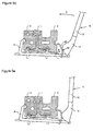
- the cam body 12 is designed such that, when the pivot pin 14 is inserted into the tool notch 21 of the connector arm 18, then the cam surface 30 will bear against the tool surface 23 of the second clip member 9. In this condition, pivoting of the setting tool 11 in the direction of arrow T ( Figure 5d), will cause the cam body 12 and pivot pin 14 to generate very high forces simultaneously acting on the first and second clip members 8, 9 to force the second clip member 9 toward the clamping arm 16 against the resistance of the rail seals 2, 3 on opposite sides of the rail 1.
- the pivot pin 14 can be removed from the tool notch 21 of the connector arm 18, and the setting tool 11 removed for reuse with another clip 7.
- pivoting the setting tool 11 in the tool notch 21 causes the cam surface 30 of the cam body 12 to apply a force to the tool surface 23 of the second clip member 9.
- This force is distributed between the upper and lower end portions 22, 24 of the second clip member 9, thereby causing compression of the rail seals 2, 3 between the clamp arm 16 and the second clip member 9, and rotation of the second clip member in the direction of arrow R as the lower end portion 24 continues to advance.
- Rotation of the second clip member is limited by the height n of the opening 25. That is, the second clip member 9 will rotate until the upper and lower interior surfaces 26, 27 of the opening 25 contact respective upper and lower surfaces of the connector arm 18.
- the upper lip 28 engages one of the notches 19, and contact between the lower lip 29 and the lower surface of the contact arm 18 prevents disengagement of the upper lip 28, so that rearward movement of the lower end portion 24 of the second clip member 9 (and thus releasing the compression of the rail seals 2, 3 within the assembled clip 7) is prevented.
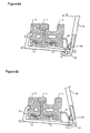
- the releasing tool 31 comprises a hook member 32, and a pressure bar 33 mounted on the end of a lever arm 13.
- the hook member 32 and pressure bar 33 are mounted on the opposite end of the lever arm 13 of the setting tool 11.
- the hook member 32 can be provided as a pair of opposed hooks 34, 35 arranged to straddle the connector arm 18 when in use.
- the hook member 32 and pressure bar 33 are designed so as to cooperatively engage opposite sides of the lower end portion 24 of the second clip member 9, as shown in Figures 6a and 6b. In this condition, rotation of the releasing tool 31 in the direction of the arrow U will cause rotation of the lower end portion 24 of the second clip member 9, which releases me second clip member 9 as described above.
Landscapes
- Engineering & Computer Science (AREA)
- Architecture (AREA)
- Civil Engineering (AREA)
- Structural Engineering (AREA)
- Clamps And Clips (AREA)
- Machines For Laying And Maintaining Railways (AREA)
- Gripping Jigs, Holding Jigs, And Positioning Jigs (AREA)
- Forklifts And Lifting Vehicles (AREA)
- Connection Of Plates (AREA)
Claims (19)
- Vorrichtung zum Befestigen eines ersten (2) und eines zweiten (3) Schienendichtungselements an entsprechenden gegenüberliegenden Seiten einer Schiene (1), wobei die Vorrichtung Folgendes umfasst(a) ein erstes Klammerelement (8), das zum wirksamen Eingreifen in das an einer Seite der Schiene (1) angeordnete erste Schienendichtungselement (2) fähig ist und einen länglichen Verbindungsarm (18) umfasst, der fähig ist, sich unter der Schiene hindurch zu erstrecken und von der gegenüberliegenden Seite der Schiene gegenüber dem ersten Schienendichtungselement um eine Länge vorzustehen;(b) ein zweites Klammerelement (9), das zum wirksamen Eingreifen in das an einer Seite der Schiene (1) gegenüber dem ersten Schienendichtungselement angeordnete zweite Schienendichtungselement (3) fähig ist,
wobei die Vorrichtung dadurch gekennzeichnet ist, dass das zweite Klammerelement eine Öffnung (25) umfasst, die zur gleitenden Aufnahme eines freien Endes des Verbindungsarms fähig ist und dassc) Sperrmittel (10) am Verbindungsarm und am zweiten Klammerelement in zusammenwirkender Beziehung bereitgestellt sind, um die Gleitbewegung des zweiten Klammerelements in eine erste Richtung hin zum Klemmarm zuzulassen und die unerwünschte Gleitbewegung des zweiten Klammerelements in die entgegengesetzte Richtung zu verhindern. - Vorrichtung nach Anspruch 1, worin das erste Klammerelement (8) ein im Allgemeinen L-förmiger Körper mit zwei Armen von ungleicher Länge ist, wobei der kürzere der beiden Arme einen Klemmarm zum Eingreifen in das erste Schienendichtungselement definiert und der längere der beiden Arme den Verbindungsarm (18) definiert.
- Vorrichtung nach Anspruch 2, worin das erste Klammerelement (8) zudem ein in der Nähe eines freien Endes des Klemmarms bereitgestelltes Kontaktpolster umfasst, wobei das Kontaktpolster so wirkt, dass eine unangemessene Verformung oder Beschädigung des ersten Schienendichtungselement (2) verhindert wird.
- Vorrichtung nach Anspruch 2, worin das erste Klammerelement (2) zudem eine in der Nähe eines freien Endes des Verbindungsarms bereitgestellte Werkzeugnut umfasst.
- Vorrichtung nach Anspruch 1, worin das zweite Klammerelement (3) einen oberen Abschnitt und einen unteren Abschnitt umfasst, wobei der obere Abschnitt ein zweites Kontaktpolster zum wirksamen Eingreifen in das zweite Schienendichtungselement definiert und der untere Abschnitt die Öffnung (25) umfasst.
- Vorrichtung nach Anspruch 5, worin die Breite der Öffnung (25) ausreichend groß ist, um gemeinsam mit den Seiten des Verbindungsarms (18) einen kleinen Spalt auszubilden, sodass das zweite Klammerelement einfach entlang dem Verbindungsarm (18) gleiten kann und gleichzeitig eine wesentliche Fehlausrichtung zwischen dem zweiten Klammerelement und dem Klemmarm des ersten Klammerelements verhindert wird.
- Vorrichtung nach Anspruch 5, worin die Höhe der Öffnung (25) ausreichend größer als die Höhe des Verbindungsarms (18) ist, sodass das zweite Klammerelement zur Schwenkbewegung entlang einer Längsebene des ersten Klammerelements um einen Winkel fähig ist.
- Vorrichtung nach Anspruch 5, worin der obere Abschnitt des zweiten Klammerelements (9) gebogen und der untere Abschnitt desselben im Allgemeinen planar ist.
- Vorrichtung nach Anspruch 5, worin das zweite Klammerelement (9) weiters eine am Mittelabschnitt des zweiten Klammerelements zwischen dessen oberem und unterem Abschnitt bereitgestellte Werkzeugoberflächenseite umfasst, wobei das zweite Klammerelement als Reaktion auf eine auf die Werkzeugoberfläche wirkende Kraft auf dem Verbindungsarm (18) gleiten kann.
- Vorrichtung nach Anspruch 9, worin der Mittelabschnitt des die Werkzeugoberfläche definierenden Körpers im Allgemeinen planar ist.
- Vorrichtung nach Anspruch 10, worin der untere Abschnitt des zweiten Klammerelements (9) und der die Werkzeugoberfläche definierende Mittelabschnitt derselben in einem Winkel zueinander ausgerichtet sind.
- Vorrichtung nach Anspruch 1, worin das Sperrmittel (10) eine an der Oberseite des Verbindungsarms bereitgestellte Riegelnut umfasst, wobei die Riegelnut angepasst ist, um eine über die Riegelnut hinaus gehende Gleitbewegung des zweiten Klammerelements in eine zum Klemmarm (18) des ersten Klammerelements (8) führende erste Richtung zuzulassen, und zudem fähig ist, wirksam in einen Abschnitt des zweiten Klammerelements (9) einzugreifen, um eine Gleitbewegung dessen in eine vom Klemmarm des ersten Klammerelements weg führende zweite Richtung zu verhindern.
- Vorrichtung nach Anspruch 12, worin das Sperrmittel (10) weiters einen oberen Rand der Öffnung des zweiten Klammerelements umfasst, wobei der obere Rand mit der Riegelnut in Eingriff bringbar ist, um eine vom Klemmarm (18) des ersten Klammerelements weg führende Gleitbewegung des zweiten Klammerelements zu verhindern.
- Vorrichtung nach Anspruch 13, worin das Sperrmittel (10) weiters einen unteren Rand der Öffnung des zweiten Klammerelements umfasst, wobei der untere Rand wirksam mit einer entsprechenden Unterseite des Verbindungsarms (18) in Eingriff bringbar ist, um durch die vom Klemmarm des ersten Klammerelements weg führende Schwenkbewegung des zweiten Klammerelements den Eingriff des oberen Rands der Öffnung in die Riegelnut zu veranlassen.
- Vorrichtung nach Anspruch 12, worin eine Vielzahl von Riegelnuten (28) an der Oberseite des Verbindungsarms (18) bereitgestellt sind.
- Vorrichtung nach Anspruch 4, weiters umfassend ein Werkzeug (31), das fähig ist, lösbar mit dem Verbindungsarm (18) und dem zweiten Klammerelement gekoppelt zu werden, um das zweite Klammerelement zur Gleitbewegung hin zum Klammerarm des ersten Klammerelements zwangzuführen, um das erste und das zweite Schienendichtungselement (8, 9) an der Verwendungsstelle festzuklammern, und um zum In-Eingriff-Bringen der Sperrmittel, um eine unerwünschte Bewegung des zweiten Klammerelements weg vom ersten Klammerelements zu verhindern.
- Vorrichtung nach Anspruch 16, worin das Werkzeug (31) einen zum lösbaren Eingriff mit der Werkzeugnut des Arms fähigen Gelenkzapfen (33) und eine zum Eingriff mit der Werkzeugoberfläche des zweiten Klammerelements (9) fähige Nockenoberfläche umfasst, wodurch die Bewegung des zweiten Klammerelements hin zum Klemmarm durch das Einführen des Gelenkzapfens (33) in die Werkzeugnut und das darauf folgende Drehen des Werkszeugs um den Gelenkzapfen (33) ausgelöst wird.
- Verfahren zum Anlegen einer Vorrichtung gemäß Anspruch 4, wobei das Verfahren ein Werkzeug einsetzt, das Folgendes umfasst:wobei das Einstellen der Vorrichtung umgesetzt wird, indem der Gelenkzapfen (33) in die Werkzeugnut eingeführt und daraufhin das Werkszeug um den Gelenkzapfen gedreht wird, um die Bewegung des zweiten Klammerelements hin zum Klemmarm zu erzwingen und gleichzeitig die Sperrmittel in Eingriff zu bringen, um eine weitere unerwünschte Bewegung des zweiten Klammerelements (9) weg vom Klemmarm (16) zu verhindern.(a) einen Hebelarm;(b) einen Nockenkörper, der an einem freien Ende des Hebelarms bereitgestellt ist; und(c) einen Gelenkzapfen, der an einem Anlauf des Nockenkörpers bereitgestellt ist;
unerwünschte Bewegung des zweiten Klammerelements (9) weg vom Klemmarm (16) zu verhindern. - Verfahren zum Entfernen der Vorrichtung gemäß Anspruch 4, wobei das Verfahren ein Werkzeug einsetzt, das Folgendes umfasst:wobei der Hakenkörper und die Druckstange bereitgestellt sind, um in einen unteren Abschnitt des zweiten Klammerelements (9) einzugreifen, sodass das Drehen des Werkzeugs ein Kräftepaar an den unteren Abschnitt des zweiten Klammerelements anlegt, wobei das Kräftepaar so wirkt, dass die Drehung des unteren Abschnitts verursacht und so die Sperrmittel (10) der Vorrichtung gelöst werden.(a) einen Hebelarm;(b) einen Hakenkörper, der an einem freien Ende des Hebelarms bereitgestellt ist; und(c) eine Druckstange;
Applications Claiming Priority (2)
| Application Number | Priority Date | Filing Date | Title |
|---|---|---|---|
| CA002251490A CA2251490C (en) | 1998-10-22 | 1998-10-22 | Two-piece rail seal clip and tool for installing same |
| CA2251490 | 1998-10-22 |
Publications (2)
| Publication Number | Publication Date |
|---|---|
| EP0995837A1 EP0995837A1 (de) | 2000-04-26 |
| EP0995837B1 true EP0995837B1 (de) | 2005-08-03 |
Family
ID=4162953
Family Applications (1)
| Application Number | Title | Priority Date | Filing Date |
|---|---|---|---|
| EP99308315A Expired - Lifetime EP0995837B1 (de) | 1998-10-22 | 1999-10-21 | Zweiteilige Schienenklammer und Werkzeug für ihre Befestigung |
Country Status (5)
| Country | Link |
|---|---|
| US (1) | US6213407B1 (de) |
| EP (1) | EP0995837B1 (de) |
| AT (1) | ATE301209T1 (de) |
| CA (1) | CA2251490C (de) |
| DE (1) | DE69926463T2 (de) |
Cited By (1)
| Publication number | Priority date | Publication date | Assignee | Title |
|---|---|---|---|---|
| WO2021218713A1 (en) * | 2020-04-28 | 2021-11-04 | Talent Power Limited | Rail damper mounting apparatus and rail damper systems containing the same |
Families Citing this family (16)
| Publication number | Priority date | Publication date | Assignee | Title |
|---|---|---|---|---|
| DE10138803A1 (de) * | 2001-08-14 | 2003-02-27 | Boegl Max Bauunternehmung Gmbh | Verfahren zum kontinuierlichen Lagern einer Schiene auf einer festen Fahrbahn sowie Justiereinrichtung und feste Fahrbahn |
| GB0613080D0 (en) * | 2006-07-03 | 2006-08-09 | Corus Uk Ltd | Rail dampers |
| US7992797B2 (en) * | 2007-04-18 | 2011-08-09 | Fastrax Industries, Inc. | Railroad signal line attachment clip |
| US20090178248A1 (en) * | 2008-01-16 | 2009-07-16 | Performance Polymers Inc. | Fixed length clamp assembly |
| CA2633014A1 (en) * | 2008-05-23 | 2009-11-23 | Polycorp Ltd. | Two-piece rail seal clip and tool for installing same |
| EP2314768B1 (de) * | 2009-10-22 | 2013-09-18 | Vossloh Werke GmbH | Schienenstegbedämpfung zur Schallreduzierung an Eisenbahngleisen |
| US8245950B2 (en) | 2010-06-30 | 2012-08-21 | Polycorp Ltd. | Removable rail seal |
| US8555943B2 (en) | 2010-07-15 | 2013-10-15 | Timothy J. Flynn | Method for printing individual labels |
| US9074326B2 (en) | 2011-06-02 | 2015-07-07 | Dacon Industries | Hinged rail seal clip |
| DE102012106138B4 (de) * | 2012-07-09 | 2016-09-22 | Dätwyler Sealing Technologies Deutschland Gmbh | Schienenanordnung |
| US9074327B2 (en) * | 2012-08-24 | 2015-07-07 | David L. Reichle | Railroad attachment clamp |
| WO2016124910A1 (en) * | 2015-02-03 | 2016-08-11 | Codiun Limited | A rail clamp |
| GB201501794D0 (en) * | 2015-02-03 | 2015-03-18 | Codiun Ltd | A rail clamp |
| US11174597B2 (en) | 2018-09-17 | 2021-11-16 | Polycorp Ltd. | System and method for securing tuned mass dampers to rail |
| US11268246B2 (en) | 2018-09-17 | 2022-03-08 | Polycorp Ltd. | System and method for securing tuned mass dampers to rail |
| WO2023108194A1 (en) * | 2021-12-14 | 2023-06-22 | Cold Forged Products No. 1 Pty Limited | Rail clamp |
Family Cites Families (20)
| Publication number | Priority date | Publication date | Assignee | Title |
|---|---|---|---|---|
| US916277A (en) * | 1907-10-19 | 1909-03-23 | Matthew J Dawkins | Railroad-track fastening. |
| US1050457A (en) * | 1912-09-19 | 1913-01-14 | Peter Herm Hellner | Rail-fastening. |
| US1092198A (en) * | 1913-08-12 | 1914-04-07 | Charles A Allen | Railroad-tie. |
| US1230703A (en) * | 1916-09-23 | 1917-06-19 | Gregg Company Ltd | Railway-tie and fastener. |
| US1397776A (en) * | 1921-08-12 | 1921-11-22 | Twin City Forge & Foundry Comp | Combination tie-plate and anticreeper for rails |
| US1440062A (en) * | 1922-09-09 | 1922-12-26 | Joseph E Katz | Anticreeping clamp |
| SE434862B (sv) | 1980-01-30 | 1984-08-20 | A Betong Ab | Sett att anordna formforband for plankorsningsplattor vid overfartsstelle till jernvegsspar |
| CA1197826A (en) | 1982-06-02 | 1985-12-10 | William D. Maass | Railroad crossing structure |
| US4793545A (en) | 1987-07-14 | 1988-12-27 | Construction Polymers Company | Embedded track assembly |
| US4880158A (en) | 1987-11-27 | 1989-11-14 | Cook Louis V | Surface grade crossing structure |
| US4919330A (en) | 1989-03-03 | 1990-04-24 | Winger James W | Quick release railroad highway crossing |
| DE4000992C2 (de) * | 1990-01-16 | 1999-02-04 | Phoenix Ag | Schiene mit Dämpfungselement |
| EP0593608A1 (de) * | 1991-07-11 | 1994-04-27 | Jenbacher Energiesysteme Aktiengesellschaft | Lärmschutzvorrichtung für eisenbahngleise |
| US5465903A (en) | 1992-02-03 | 1995-11-14 | Riedel Omni Rubber Products, Inc. | Mounting plate for fixing elastomeric grade crossing panels to ties |
| GB9202992D0 (en) * | 1992-02-13 | 1992-03-25 | Ashdown Environmental Limited | Noise suppression systems |
| US5577662A (en) | 1994-04-20 | 1996-11-26 | Hogue; Thomas A. | Embedded railway track system |
| DE59508918D1 (de) * | 1994-07-16 | 2001-02-01 | Phoenix Ag | Schienenanordnung |
| US5655711A (en) | 1995-06-06 | 1997-08-12 | Hull; William K. | Prefabricated embedded railway track system |
| US5609294A (en) | 1995-07-21 | 1997-03-11 | Lucas, Jr.; Joseph | Railroad track assembly and method |
| US5622312A (en) | 1995-09-26 | 1997-04-22 | Martin; John K. | Rail track surface structure |
-
1998
- 1998-10-22 CA CA002251490A patent/CA2251490C/en not_active Expired - Lifetime
- 1998-11-24 US US09/198,365 patent/US6213407B1/en not_active Expired - Lifetime
-
1999
- 1999-10-21 AT AT99308315T patent/ATE301209T1/de not_active IP Right Cessation
- 1999-10-21 DE DE69926463T patent/DE69926463T2/de not_active Expired - Lifetime
- 1999-10-21 EP EP99308315A patent/EP0995837B1/de not_active Expired - Lifetime
Cited By (4)
| Publication number | Priority date | Publication date | Assignee | Title |
|---|---|---|---|---|
| WO2021218713A1 (en) * | 2020-04-28 | 2021-11-04 | Talent Power Limited | Rail damper mounting apparatus and rail damper systems containing the same |
| GB2609732A (en) * | 2020-04-28 | 2023-02-15 | Talent Power Ltd | Rail damper mounting apparatus and rail damper systems containing the same |
| AU2021263618B2 (en) * | 2020-04-28 | 2023-06-15 | Talent Power Limited | Rail damper mounting apparatus and rail damper systems containing the same |
| GB2609732B (en) * | 2020-04-28 | 2024-09-25 | Talent Power Ltd | Rail damper mounting apparatus and rail damper systems containing the same |
Also Published As
| Publication number | Publication date |
|---|---|
| ATE301209T1 (de) | 2005-08-15 |
| EP0995837A1 (de) | 2000-04-26 |
| DE69926463T2 (de) | 2006-06-01 |
| CA2251490C (en) | 2004-02-03 |
| CA2251490A1 (en) | 2000-04-22 |
| DE69926463D1 (de) | 2005-09-08 |
| US6213407B1 (en) | 2001-04-10 |
Similar Documents
| Publication | Publication Date | Title |
|---|---|---|
| AU2008100834B4 (en) | Two-piece rail seal clip and tool for installing same | |
| CA2251490C (en) | Two-piece rail seal clip and tool for installing same | |
| CA2737370C (en) | Wiping bar quick clamp | |
| EP2279142B1 (de) | Entfernbarer patronenreiniger | |
| US8757360B2 (en) | Removable cartridge cleaner | |
| US5297482A (en) | Rail threader | |
| CA2881247C (en) | Detachable traction system for endless track vehicles | |
| AU754221B2 (en) | Guide bar mount for a tree harvester | |
| US5095603A (en) | Drum brake service tool and method of using the same | |
| US6108882A (en) | Brake spring tool | |
| GB2439834A (en) | Clip for a rail damper | |
| EP2370301A2 (de) | Scharnierklemme | |
| CA2240624C (en) | System for securing interface strips at road/rail crossing | |
| US6925697B2 (en) | Guard rail tool | |
| EP1253244B1 (de) | Schienenbefestigungseinrichtung | |
| KR101043945B1 (ko) | 전철기 상판 시스템 | |
| EP1329364B1 (de) | Seitliches Fahrschutzsystem | |
| US20060130305A1 (en) | Wear strip replacement method and apparatus | |
| US20040034979A1 (en) | Wear strip replacement method and apparatus | |
| CA2229709A1 (en) | Temporary rail bridge | |
| KR101324833B1 (ko) | 다관절 벨트타입 스노 체인과 그 장착장치 및 장착시스템 | |
| KR102029737B1 (ko) | 철도의 융설장치 고정클립 | |
| EP0844960A1 (de) | Gelenkige fahrzeug raupenkette für gepanzerte fahrzeuge | |
| KR0130555Y1 (ko) | 차량용 빙판길 제동장치 | |
| SU1539107A1 (ru) | Ударно-т говое устройство рельсового состава |
Legal Events
| Date | Code | Title | Description |
|---|---|---|---|
| PUAI | Public reference made under article 153(3) epc to a published international application that has entered the european phase |
Free format text: ORIGINAL CODE: 0009012 |
|
| AK | Designated contracting states |
Kind code of ref document: A1 Designated state(s): AT BE CH CY DE DK ES FI FR GB GR IE IT LI LU MC NL PT SE |
|
| AX | Request for extension of the european patent |
Free format text: AL;LT;LV;MK;RO;SI |
|
| 17P | Request for examination filed |
Effective date: 20001016 |
|
| AKX | Designation fees paid |
Free format text: AT BE CH CY DE DK ES FI FR GB GR IE IT LI LU MC NL PT SE |
|
| GRAP | Despatch of communication of intention to grant a patent |
Free format text: ORIGINAL CODE: EPIDOSNIGR1 |
|
| GRAS | Grant fee paid |
Free format text: ORIGINAL CODE: EPIDOSNIGR3 |
|
| GRAA | (expected) grant |
Free format text: ORIGINAL CODE: 0009210 |
|
| AK | Designated contracting states |
Kind code of ref document: B1 Designated state(s): AT BE CH CY DE DK ES FI FR GB GR IE IT LI LU MC NL PT SE |
|
| PG25 | Lapsed in a contracting state [announced via postgrant information from national office to epo] |
Ref country code: NL Free format text: LAPSE BECAUSE OF FAILURE TO SUBMIT A TRANSLATION OF THE DESCRIPTION OR TO PAY THE FEE WITHIN THE PRESCRIBED TIME-LIMIT Effective date: 20050803 Ref country code: LI Free format text: LAPSE BECAUSE OF FAILURE TO SUBMIT A TRANSLATION OF THE DESCRIPTION OR TO PAY THE FEE WITHIN THE PRESCRIBED TIME-LIMIT Effective date: 20050803 Ref country code: FI Free format text: LAPSE BECAUSE OF FAILURE TO SUBMIT A TRANSLATION OF THE DESCRIPTION OR TO PAY THE FEE WITHIN THE PRESCRIBED TIME-LIMIT Effective date: 20050803 Ref country code: CH Free format text: LAPSE BECAUSE OF FAILURE TO SUBMIT A TRANSLATION OF THE DESCRIPTION OR TO PAY THE FEE WITHIN THE PRESCRIBED TIME-LIMIT Effective date: 20050803 Ref country code: AT Free format text: LAPSE BECAUSE OF FAILURE TO SUBMIT A TRANSLATION OF THE DESCRIPTION OR TO PAY THE FEE WITHIN THE PRESCRIBED TIME-LIMIT Effective date: 20050803 |
|
| REG | Reference to a national code |
Ref country code: GB Ref legal event code: FG4D |
|
| REG | Reference to a national code |
Ref country code: CH Ref legal event code: EP |
|
| REG | Reference to a national code |
Ref country code: IE Ref legal event code: FG4D |
|
| REF | Corresponds to: |
Ref document number: 69926463 Country of ref document: DE Date of ref document: 20050908 Kind code of ref document: P |
|
| PG25 | Lapsed in a contracting state [announced via postgrant information from national office to epo] |
Ref country code: IE Free format text: LAPSE BECAUSE OF NON-PAYMENT OF DUE FEES Effective date: 20051021 Ref country code: CY Free format text: LAPSE BECAUSE OF FAILURE TO SUBMIT A TRANSLATION OF THE DESCRIPTION OR TO PAY THE FEE WITHIN THE PRESCRIBED TIME-LIMIT Effective date: 20051021 |
|
| PG25 | Lapsed in a contracting state [announced via postgrant information from national office to epo] |
Ref country code: MC Free format text: LAPSE BECAUSE OF NON-PAYMENT OF DUE FEES Effective date: 20051031 Ref country code: LU Free format text: LAPSE BECAUSE OF NON-PAYMENT OF DUE FEES Effective date: 20051031 |
|
| PG25 | Lapsed in a contracting state [announced via postgrant information from national office to epo] |
Ref country code: SE Free format text: LAPSE BECAUSE OF FAILURE TO SUBMIT A TRANSLATION OF THE DESCRIPTION OR TO PAY THE FEE WITHIN THE PRESCRIBED TIME-LIMIT Effective date: 20051103 Ref country code: GR Free format text: LAPSE BECAUSE OF FAILURE TO SUBMIT A TRANSLATION OF THE DESCRIPTION OR TO PAY THE FEE WITHIN THE PRESCRIBED TIME-LIMIT Effective date: 20051103 Ref country code: GB Free format text: LAPSE BECAUSE OF NON-PAYMENT OF DUE FEES Effective date: 20051103 Ref country code: DK Free format text: LAPSE BECAUSE OF FAILURE TO SUBMIT A TRANSLATION OF THE DESCRIPTION OR TO PAY THE FEE WITHIN THE PRESCRIBED TIME-LIMIT Effective date: 20051103 |
|
| PG25 | Lapsed in a contracting state [announced via postgrant information from national office to epo] |
Ref country code: ES Free format text: LAPSE BECAUSE OF FAILURE TO SUBMIT A TRANSLATION OF THE DESCRIPTION OR TO PAY THE FEE WITHIN THE PRESCRIBED TIME-LIMIT Effective date: 20051114 |
|
| PG25 | Lapsed in a contracting state [announced via postgrant information from national office to epo] |
Ref country code: PT Free format text: LAPSE BECAUSE OF FAILURE TO SUBMIT A TRANSLATION OF THE DESCRIPTION OR TO PAY THE FEE WITHIN THE PRESCRIBED TIME-LIMIT Effective date: 20060103 |
|
| NLV1 | Nl: lapsed or annulled due to failure to fulfill the requirements of art. 29p and 29m of the patents act | ||
| REG | Reference to a national code |
Ref country code: CH Ref legal event code: PL |
|
| ET | Fr: translation filed | ||
| PLBE | No opposition filed within time limit |
Free format text: ORIGINAL CODE: 0009261 |
|
| STAA | Information on the status of an ep patent application or granted ep patent |
Free format text: STATUS: NO OPPOSITION FILED WITHIN TIME LIMIT |
|
| 26N | No opposition filed |
Effective date: 20060504 |
|
| GBPC | Gb: european patent ceased through non-payment of renewal fee |
Effective date: 20051103 |
|
| REG | Reference to a national code |
Ref country code: IE Ref legal event code: MM4A |
|
| PGFP | Annual fee paid to national office [announced via postgrant information from national office to epo] |
Ref country code: DE Payment date: 20100927 Year of fee payment: 12 |
|
| PGFP | Annual fee paid to national office [announced via postgrant information from national office to epo] |
Ref country code: IT Payment date: 20100929 Year of fee payment: 12 |
|
| PGFP | Annual fee paid to national office [announced via postgrant information from national office to epo] |
Ref country code: BE Payment date: 20111028 Year of fee payment: 13 Ref country code: FR Payment date: 20111103 Year of fee payment: 13 |
|
| BERE | Be: lapsed |
Owner name: *POLYCORP INC. Effective date: 20121031 |
|
| REG | Reference to a national code |
Ref country code: FR Ref legal event code: ST Effective date: 20130628 |
|
| PG25 | Lapsed in a contracting state [announced via postgrant information from national office to epo] |
Ref country code: DE Free format text: LAPSE BECAUSE OF NON-PAYMENT OF DUE FEES Effective date: 20130501 Ref country code: BE Free format text: LAPSE BECAUSE OF NON-PAYMENT OF DUE FEES Effective date: 20121031 |
|
| REG | Reference to a national code |
Ref country code: DE Ref legal event code: R119 Ref document number: 69926463 Country of ref document: DE Effective date: 20130501 |
|
| PG25 | Lapsed in a contracting state [announced via postgrant information from national office to epo] |
Ref country code: FR Free format text: LAPSE BECAUSE OF NON-PAYMENT OF DUE FEES Effective date: 20121031 Ref country code: IT Free format text: LAPSE BECAUSE OF NON-PAYMENT OF DUE FEES Effective date: 20121021 |