EP0995864B1 - Système de verrouillage électromécanique - Google Patents
Système de verrouillage électromécanique Download PDFInfo
- Publication number
- EP0995864B1 EP0995864B1 EP99120410A EP99120410A EP0995864B1 EP 0995864 B1 EP0995864 B1 EP 0995864B1 EP 99120410 A EP99120410 A EP 99120410A EP 99120410 A EP99120410 A EP 99120410A EP 0995864 B1 EP0995864 B1 EP 0995864B1
- Authority
- EP
- European Patent Office
- Prior art keywords
- key
- control unit
- coupling assembly
- unit
- assembly
- Prior art date
- Legal status (The legal status is an assumption and is not a legal conclusion. Google has not performed a legal analysis and makes no representation as to the accuracy of the status listed.)
- Expired - Lifetime
Links
- 230000008878 coupling Effects 0.000 claims abstract description 82
- 238000010168 coupling process Methods 0.000 claims abstract description 82
- 238000005859 coupling reaction Methods 0.000 claims abstract description 82
- 238000004891 communication Methods 0.000 claims abstract description 29
- 230000006698 induction Effects 0.000 claims description 22
- 125000006850 spacer group Chemical group 0.000 claims description 17
- 239000003990 capacitor Substances 0.000 claims description 5
- 230000000712 assembly Effects 0.000 claims description 3
- 238000000429 assembly Methods 0.000 claims description 3
- 239000010445 mica Substances 0.000 claims description 3
- 229910052618 mica group Inorganic materials 0.000 claims description 3
- 238000010276 construction Methods 0.000 claims 1
- 238000001125 extrusion Methods 0.000 claims 1
- 239000013589 supplement Substances 0.000 claims 1
- 229920002994 synthetic fiber Polymers 0.000 claims 1
- 230000007246 mechanism Effects 0.000 description 6
- 238000000034 method Methods 0.000 description 5
- 238000005538 encapsulation Methods 0.000 description 3
- 230000004323 axial length Effects 0.000 description 2
- 230000000903 blocking effect Effects 0.000 description 2
- 238000005553 drilling Methods 0.000 description 2
- 239000012777 electrically insulating material Substances 0.000 description 2
- 210000000056 organ Anatomy 0.000 description 2
- 230000003213 activating effect Effects 0.000 description 1
- 230000004913 activation Effects 0.000 description 1
- 238000013475 authorization Methods 0.000 description 1
- 230000005540 biological transmission Effects 0.000 description 1
- 238000005266 casting Methods 0.000 description 1
- 230000000295 complement effect Effects 0.000 description 1
- 239000002131 composite material Substances 0.000 description 1
- 230000006835 compression Effects 0.000 description 1
- 238000007906 compression Methods 0.000 description 1
- 230000001419 dependent effect Effects 0.000 description 1
- 238000013461 design Methods 0.000 description 1
- 238000005265 energy consumption Methods 0.000 description 1
- 230000006870 function Effects 0.000 description 1
- 238000003780 insertion Methods 0.000 description 1
- 230000037431 insertion Effects 0.000 description 1
- 239000000463 material Substances 0.000 description 1
- 239000002184 metal Substances 0.000 description 1
- 230000035515 penetration Effects 0.000 description 1
- 230000008569 process Effects 0.000 description 1
- 238000009420 retrofitting Methods 0.000 description 1
- 229910001220 stainless steel Inorganic materials 0.000 description 1
- 239000010935 stainless steel Substances 0.000 description 1
- 238000004804 winding Methods 0.000 description 1
Images

Classifications
-
- E—FIXED CONSTRUCTIONS
- E05—LOCKS; KEYS; WINDOW OR DOOR FITTINGS; SAFES
- E05B—LOCKS; ACCESSORIES THEREFOR; HANDCUFFS
- E05B47/00—Operating or controlling locks or other fastening devices by electric or magnetic means
- E05B47/06—Controlling mechanically-operated bolts by electro-magnetically-operated detents
- E05B47/0611—Cylinder locks with electromagnetic control
- E05B47/0638—Cylinder locks with electromagnetic control by disconnecting the rotor
- E05B47/0646—Cylinder locks with electromagnetic control by disconnecting the rotor radially
- E05B47/0649—Cylinder locks with electromagnetic control by disconnecting the rotor radially with a rectilinearly moveable coupling element
-
- E—FIXED CONSTRUCTIONS
- E05—LOCKS; KEYS; WINDOW OR DOOR FITTINGS; SAFES
- E05B—LOCKS; ACCESSORIES THEREFOR; HANDCUFFS
- E05B47/00—Operating or controlling locks or other fastening devices by electric or magnetic means
- E05B47/06—Controlling mechanically-operated bolts by electro-magnetically-operated detents
- E05B47/0611—Cylinder locks with electromagnetic control
- E05B47/0615—Cylinder locks with electromagnetic control operated by handles, e.g. by knobs
-
- G—PHYSICS
- G07—CHECKING-DEVICES
- G07C—TIME OR ATTENDANCE REGISTERS; REGISTERING OR INDICATING THE WORKING OF MACHINES; GENERATING RANDOM NUMBERS; VOTING OR LOTTERY APPARATUS; ARRANGEMENTS, SYSTEMS OR APPARATUS FOR CHECKING NOT PROVIDED FOR ELSEWHERE
- G07C9/00—Individual registration on entry or exit
- G07C9/00174—Electronically operated locks; Circuits therefor; Nonmechanical keys therefor, e.g. passive or active electrical keys or other data carriers without mechanical keys
- G07C9/00896—Electronically operated locks; Circuits therefor; Nonmechanical keys therefor, e.g. passive or active electrical keys or other data carriers without mechanical keys specially adapted for particular uses
- G07C9/00904—Electronically operated locks; Circuits therefor; Nonmechanical keys therefor, e.g. passive or active electrical keys or other data carriers without mechanical keys specially adapted for particular uses for hotels, motels, office buildings or the like
-
- E—FIXED CONSTRUCTIONS
- E05—LOCKS; KEYS; WINDOW OR DOOR FITTINGS; SAFES
- E05B—LOCKS; ACCESSORIES THEREFOR; HANDCUFFS
- E05B47/00—Operating or controlling locks or other fastening devices by electric or magnetic means
- E05B47/0001—Operating or controlling locks or other fastening devices by electric or magnetic means with electric actuators; Constructional features thereof
- E05B2047/0014—Constructional features of actuators or power transmissions therefor
- E05B2047/0015—Output elements of actuators
- E05B2047/0017—Output elements of actuators with rotary motion
-
- E—FIXED CONSTRUCTIONS
- E05—LOCKS; KEYS; WINDOW OR DOOR FITTINGS; SAFES
- E05B—LOCKS; ACCESSORIES THEREFOR; HANDCUFFS
- E05B47/00—Operating or controlling locks or other fastening devices by electric or magnetic means
- E05B47/0001—Operating or controlling locks or other fastening devices by electric or magnetic means with electric actuators; Constructional features thereof
- E05B2047/0014—Constructional features of actuators or power transmissions therefor
- E05B2047/0018—Details of actuator transmissions
- E05B2047/0026—Clutches, couplings or braking arrangements
- E05B2047/0027—Clutches, couplings or braking arrangements using centrifugal action
-
- E—FIXED CONSTRUCTIONS
- E05—LOCKS; KEYS; WINDOW OR DOOR FITTINGS; SAFES
- E05B—LOCKS; ACCESSORIES THEREFOR; HANDCUFFS
- E05B47/00—Operating or controlling locks or other fastening devices by electric or magnetic means
- E05B47/0001—Operating or controlling locks or other fastening devices by electric or magnetic means with electric actuators; Constructional features thereof
- E05B47/0012—Operating or controlling locks or other fastening devices by electric or magnetic means with electric actuators; Constructional features thereof with rotary electromotors
-
- G—PHYSICS
- G07—CHECKING-DEVICES
- G07C—TIME OR ATTENDANCE REGISTERS; REGISTERING OR INDICATING THE WORKING OF MACHINES; GENERATING RANDOM NUMBERS; VOTING OR LOTTERY APPARATUS; ARRANGEMENTS, SYSTEMS OR APPARATUS FOR CHECKING NOT PROVIDED FOR ELSEWHERE
- G07C9/00—Individual registration on entry or exit
- G07C9/00174—Electronically operated locks; Circuits therefor; Nonmechanical keys therefor, e.g. passive or active electrical keys or other data carriers without mechanical keys
- G07C2009/00753—Electronically operated locks; Circuits therefor; Nonmechanical keys therefor, e.g. passive or active electrical keys or other data carriers without mechanical keys operated by active electrical keys
- G07C2009/00769—Electronically operated locks; Circuits therefor; Nonmechanical keys therefor, e.g. passive or active electrical keys or other data carriers without mechanical keys operated by active electrical keys with data transmission performed by wireless means
- G07C2009/00777—Electronically operated locks; Circuits therefor; Nonmechanical keys therefor, e.g. passive or active electrical keys or other data carriers without mechanical keys operated by active electrical keys with data transmission performed by wireless means by induction
Definitions
- the invention relates to an electromechanical locking system for doors according to the preamble of claim 1.
- Such locking systems can be designed so that they - for example, after loss of a key - can be reprogrammed without great effort to prevent access by unauthorized persons. Unauthorized copying of electronic keys is also virtually impossible.
- the electronic assembly is activated on the other side of the blocking element.
- a closing device equipped with electronic locking components is known in which the key comprises a code transmitter and the lock unit formed by lock and lock cylinder comprises a code analyzer with an unlocking device.
- the power source is in the key and the Code Evaluator is arranged with the unlocking in the lock cylinder.
- a center contact formed at the end of the key shank is brought into contact with a spring.
- the spring is connected with its distal end stationary to an electromagnet. Furthermore, the spring is supported in its central region against a bolt.
- the coupling assembly not only serves for the mechanical non-rotatable coupling of the key with the closing element, but is also part of an electrical circuit, which is closed by operating the coupling assembly by means of the key, wherein the coupling assembly has a sliding by means of the key sliding member, which is used to produce the is shifted electrically conductive connection.
- the communication unit carried by the key is directly connected to the control unit.
- the key-facing end face of the cylinder member can be provided due to the direct connection between the control unit and the key with fittings of any strength and material properties that can make it impossible to transmit electromagnetic waves between induction coils.
- an energy source for example in the form of a battery, which supplies the control unit when the coupling assembly is actuated by means of the key can be arranged in the circuit.
- the control unit By inserting the key into the cylinder member then the control unit is turned on and at the same time the exchange of example one Access code containing information between the control unit and the key allows.
- a separate communication device eg. As an induction coil, and a switching device, for example in the form of a button in the key side end of the cylinder member and cable ducts for from one end of the cylinder member to the other leading connecting lines can be omitted according to the invention.
- the coupling assembly in particular a sliding member of the coupling assembly, by the key operation in the direction of a driving position biased.
- the communication unit comprises a key-specific communication element which is integrated in a designed as a transponder unit electronic assembly of the key, and a electronic assembly of the control unit associated lock-specific communication element, wherein the communication organs for communication with each other are formed by electromagnetic waves and preferably each comprise at least one induction coil.
- the key thus carries the essential for an exchange of information components of the locking system, which in particular when, according to a further preferred embodiment of the invention, the control unit is housed in a housing of a knob, only the coupling assembly is to be accommodated in the cylinder member.
- a transponder unit of the key extends at least partially through the induction coil of the control unit, wherein preferably the induction coil is wound directly onto the transponder unit.
- the cylinder member is designed as a cylinder adapter which can be used with the lock instead of a lock cylinder, in particular a standardized profile cylinder.
- a rotary knob in which, according to the already mentioned preferred embodiment of the invention, the control unit is housed, with the closing element makes it possible to lock the door from the inside at any time and unlock.
- the rotary knob can be decoupled from the closing element to allow the use of the locking system according to the invention - while maintaining the space available in a rotary knob - in conjunction with panic locks in which the lock mechanism can be opened at any time from the inside by a door handle to open the door can be acted upon and the door must not be locked by means of a door inside the associated knob.
- a switching unit of the coupling assembly which is adjustable for the adjustment of the coupling assembly from the freewheeling state in the driving state by a motor of the control unit, as a centrifugal unit is formed, which can be displaced by a motor of the control unit in rotation disc and on the a slide of the sliding member facing the pulley comprises at least one centrifugal element, wherein in the rotating disk in the freewheeling condition by the centrifugal force obstructed path for a direction of the switching unit projecting spine of the slider is released to the control unit.
- centrifugal force unit is a simple, few items requiring and compact structure having and yet Reliably working arrangement for adjusting the coupling assembly created.
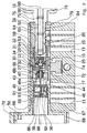
- the locking system according to FIG. 1 comprises a cylinder member 10, which is designed as a cylinder adapter, ie as a replacement piece for a standardized profile cylinder and thus can be used with conventional mortise locks for doors.
- a closure member 12 is rotatably mounted about a rotation axis 98 which has a cam 72 for applying a locking mechanism of the castle.
- the cylinder member 10 is provided with a bore 74 for a forend screw for rotationally fixed fixing of the cylinder member 10 in the lock.
- the cylinder member 10 is constructed approximately symmetrically, d. H. the closing element 12 is arranged in a recess 17 between two approximately the same axial length having portions of the cylinder member 10.
- the cylinder member 10 may be executed as a function of the particular circumstances, in particular the dimensions of the door panel, but also asymmetrically. For example, the portion of the cylinder member 10 assigned to a door outer side can be shortened relative to the other portion.
- the locking system further comprises a key 16, the key body 60 comprises a handle portion 78 and a shaft portion 84.
- the grip part 78 which carries a communication unit 18 explained in more detail elsewhere, is provided with an encapsulation 80 made of plastic surrounding the grip part 78 and the communication unit 18.
- a recess 82 is provided, the z. B. allows attachment of the key 16 to a key fob.
- the communication unit 18 comprises a transponder unit 52 and an induction coil 54 wound on the transponder unit 52, one end of which is soldered to the grip part 78 of the key body 60 and the other end to a printed circuit board 56.
- the circuit board 56 is glued into a channel-like recess of the key body 60, which over the from Handle part 78 pioneering front end of the shaft portion 84 protrudes and forms a contact tip 58.
- the transponder unit 52 is received by the rear, fork-shaped end of the circuit board 56 and fixedly connected to the circuit board 56 and the key body 60 by pouring into an electrically insulating material (not shown).
- a mica plate 62 is glued, which extends along the channel-like recess of the key body 60 and the circuit board 56 with respect to the key body 60 electrically isolated. Openings 76 allow an intimate positive connection between the shaft portion 84 of the key body 60 and an electrically insulating material (not shown), with which the channel-like recess can be poured to protect the circuit board 56 from external influences.
- a hollow shaft portion 66 of a knob 68 is inserted, which comprises an integrally connected to the hollow shaft portion 66 housing 50 and a cap 70 made of metal or plastic.
- the cap 70 is screwed or latched to the housing 50.
- each component may be provided with two diametrically opposed extensions or recesses or cuts.
- any number of spacers between the hollow shaft portion 66 of the knob 68 and the closing element 12 can be arranged. Also, a direct rotationally fixed coupling between the hollow shaft portion 66 and the closing element 12 without spacers is possible in principle, in which case, however, explained in more detail elsewhere recess 46 which is formed in the spacer 48 a, should be provided in the hollow shaft portion 66.
- knob 68 In order to enable the use of the locking system with panic locks, can be provided for a decoupling between the knob 68 and the closing element 12, for example by omitting the frontal extensions or recesses or cuts on the hollow shaft portion 66 or one of the spacers 48a, 48b, so that the knob 68 in the cylinder member 10 is freely rotatable.
- knob 68 is a control unit, not shown, and represented only by the reference numeral 20, whose purpose will be described elsewhere.
- the locking system further comprises a rotatably mounted in the cylinder member 10, multi-part coupling assembly 14, which in Fig. 1 by the with dashed line drawn box is marked and will be explained below with reference to FIG. 2.
- the coupling assembly 14 comprises a multi-part outer sleeve which is formed by axially successively arranged, at least approximately sleeve-shaped and non-rotatably interconnected elements, namely by an inner cylinder 64, a connecting piece 94 and a receiving piece 96 of a sliding member 24.
- the rotationally fixed coupling of two axially adjacent elements takes place - as described above in connection with the closing element 12, the spacers 48a, 48b and the hollow shaft portion 66 - by the engagement between the end projections and recesses or cuts of the elements.
- the inner cylinder 64 has a keyway 65 for the key 16 and is provided at its periphery with an annular recess 63 in the region of its end facing the closing element 12.
- annular recess 63 engages an unillustrated, spring-loaded pin which sits in one of four key-side transverse bores 13 of the cylinder member 10, and on the one hand holds the inner cylinder 64 in the cylinder member 10 axially immovable and on the other in the manner of a sliding contact regardless of the angular position the inner cylinder 64 ensures good electrical contact between the inner cylinder 64 and the cylinder member 10.
- the other three transverse bores 13 of the cylinder member 10 serve to receive pin springs, together with seated in holes 15 of the inner cylinder 64 inner pins and between the pin springs and
- the inner pins arranged outer pins represent a coding that cooperates with the manner of a Stiftzurois conventional lock cylinder formed in the shaft portion 84 of the key 16 incisions 85. This ensures that the inner cylinder 64 can only be rotated in the cylinder member 10 when the key 16, which is fully inserted and designed in accordance with the coding, is rotated.
- the hollow shaft portion 50 of the knob housing 50 may be modified to be provided with recesses or cuts corresponding to the bores 15 and slots 85 of the inner cylinder 64 and the key shaft portion 84, respectively, which cooperate with spring-loaded pins extending in the remaining ones , not for axially holding the knob housing 50 in the cylinder member 10 serving rotary knob side transverse bores 11 of the cylinder member 10 sit.
- similar to a Stiftzurois trained arrangement can be ensured that the hollow shaft portion 50 engages in a certain angular position, which is tuned to the angular position of the inner cylinder 64 for removing the key 16 such that the coupling assembly 14 from the driving position to the freewheeling position can be adjusted without the risk of jamming of components. This will be discussed later.
- the key-side and rotary knob-side transverse bores 11, 13 are - if they are needed - closed by grub screws, not shown, on which the respective pins in the direction of the axis of rotation 98 biasing springs (not shown) are supported.
- the locking system comprises within the above-mentioned outer sleeve axially displaceable elements, namely a substantially disc-shaped contact portion 26 and a likewise substantially disc-shaped slide 28, which together with the receiving piece 96 and further, in connection with Fig. 2 explained components form the sliding member 24 ,
- axially displaceable elements namely a substantially disc-shaped contact portion 26 and a likewise substantially disc-shaped slide 28, which together with the receiving piece 96 and further, in connection with Fig. 2 explained components form the sliding member 24
- a corresponding number of separate, in principle corresponding to the contact portion 26 formed spacers are arranged.
- a cylindrical switching unit 22 is arranged substantially axially immovable, which is designed as a centrifugal force unit and their structure and operation in more detail with reference to FIG. 2, Fig. 3a and 3b will be explained.
- the sliding member 24 comprises a relative to the receiving piece 96 in the axial direction displaceable arrangement consisting of the contact portion 26 and the slider 28, which are interconnected by the coupling spring 30.
- the slider 28 includes an inner contact piece 32, which by Isolier Federatione 27 against an outer driver 42nd is electrically isolated. Rotary knob side, the contact piece 32 is provided with a in the direction of the switching unit 22 projecting mandrel 40.
- the contact portion 26 also has an inner contact piece 32 which is mated with a knob side 29 arranged spring receptacle.
- the contact piece 32 and the spring receptacle 29 are electrically insulated by insulating pieces 25 with respect to an outer sleeve 31.
- the contact portion 26 is located outside of the receiving piece 96 and is - in composite coupling assembly 14 - guided over its outer sleeve 31 in the connector 94.
- the coupling spring 30 is placed on facing, cylindrical projections of the contact piece 32 of the slider 28 and the spring seat 29 of the contact portion 26.
- a return spring 34 is supported at its one end in an annular groove between the rotary knob-side insulating piece 27 of the contact portion 26 and at its other end to an annular projection which is formed on the inner wall of the receiving piece 96.
- the knob 68 nearest to the spacer 48a, on which the receiving piece 96 is present is also an axial recess whose width corresponds to that of the radial extension 43 of the driver 42, formed recess 46 provided.
- the two recesses 44, 46 together form - at a certain relative angular position between the non-rotatably connected to the coupling assembly 14 key 16 and the non-rotatably connected to the closing element 12 knob 68 - together in the axial direction occidental direction occidental slot.
- the two recesses 44, 46 can - if the receiving piece 96 and the spacer 48 a formed accordingly and z. B. are inserted into each other - overlap in the axial direction.
- the mandrel 40 and the radial extension 43 in Fig. 1 and Fig. 2 can move to the left, if the above-mentioned certain relative Angular position is present.
- the sliding member 24 is then in a driving state or a driving position corresponding to the driving state of the coupling assembly 14, in which the radial extension 43 of the driver 42 sits simultaneously in the recess 44 of the receiving piece 96 and in the recess 46 of the spacer 48 a ,
- a rotation of the key 16 thus causes in this position a entrainment of the driver 42 via the receiving piece 96 and a driving of the spacer 48a on the radial extension 43 of the driver 42.
- a rotationally fixed coupling of the key 16 via the coupling assembly 14 with the closing element 12 which allows the lock mechanism by means of the key 16 to act on the cam 72 of the closing element 12.
- the printed circuit board 56, the contact piece 32 and the spring receptacle 29 of the contact portion 26, the coupling spring 30, the contact piece 32 of the slider 28 and the mandrel 40 of the contact piece 32 are made of stainless steel.
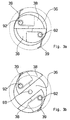
- the partially illustrated in Fig. 3a and 3b switching unit 22 of the coupling assembly 14 is formed as a centrifugal unit and comprises a disc 36, on which the sliding member 24 facing side opposite the disc 36 about axes defined by bearing pins 92 pivotable centrifugal elements 38 are arranged, of which in Fig. 1 and Fig. 2 only one is shown.
- the centrifugal elements 38 are castings.
- cap 90 forms a rotary knob side open housing for the disc 36 and the centrifugal elements 38.
- opening 91 are in the sliding member 24 facing side of the cap 90 two diametrically opposed, each provided with an internal thread holes formed, which are not visible in the figures.
- a channel 88 is provided for the output shaft of an electric motor, not shown, of the control knob 20 housed in the knob 68.
- the central axes of the channel 88 and the opening 91 in the cap 90 coincide with the axis of rotation 98.
- a grub screw 86 which is screwed through a recess in the cap 90 and a bore in the disc 36 perpendicular to the axis of rotation 98 in the switching unit 22, the motor shaft can be fixed and thus rotatably connected to the disc 36.
- Fig. 1 and Fig. 2 to the left of the switching unit 22 is on the inner wall 69 of the hollow shaft portion 66 of the housing 50, not shown, sleeve-shaped insulating piece is provided, which electrically isolates the motor housing relative to the hollow shaft portion 66.
- FIG. 3a and 3b each show a key-side view of the switching unit 22 with the cap 90 removed, wherein FIG. 3a corresponds to a freewheeling state and FIG. 3b corresponds to a driving state of the coupling assembly 14.
- the centrifugal elements 38 each have a semi-circular cross section with a radius slightly smaller than that of the disc 36 is.
- the bearing pins 92 each extend through a corner region of the centrifugal force elements 38 and stuck in formed in the disc 36 blind holes.
- the centrifugal elements 38 are arranged such that their straight sides lie in the same, the plane passing through the channel 88 of the disc 36 axis of rotation 98 level.
- the centrifugal elements 38 are displaced relative to each other so that they complete each with the closer to its bearing pin 92 corner region with the edge of the disc 36 and form a locking disc.
- the centrifugal elements 38 are respectively biased by a two-armed, serving as a return spring 39 coil spring in their freewheeling state corresponding freewheeling position shown in FIG. 3a, wherein the bearing pins 92 each extend through the winding or turns of the return springs 39.
- the return springs 39 are each with one arm completely and the other, at the free end arcuate expiring arm partially in a plane parallel to the disk plane 36 incision of the centrifugal force element 38.
- the straight expiring arm of the return springs 39 is based in each case in the region of its free end the in Fig. 3a and Fig. 3b partially schematically indicated by a dash-dotted line boundary wall of the incision.
- the other arm of the return springs 39 is supported on a wall 36 surrounding the disc 36 and the centrifugal elements 38, indicated by a dashed circle.
- the wall on which the return springs 39 (not illustrated in FIGS. 1 and 2) are supported, formed by the inner wall of the cap 90, wherein the free inner diameter of the cap 90 corresponds to the diameter of the disc 36.
- FIG. 3 a and FIG. 3 b the dashed circle has a larger diameter than the pane 36.
- Fig. 3b in which the centrifugal elements 38 are each shown in their driving state corresponding driving position, which they occupy with rotating disk 36, clearly seen that the return springs 39 are compressed.
- a gap is shown in FIG. 3b, on the previously closed by the centrifugal elements 38 path into the interior of the switching unit 22 into it, d. H. in the direction of the disc 36 is accessible.
- the centrifugal force unit is characterized in that regardless of the free inner diameter of the wall on which the return springs 39 are supported, d. H. regardless of how far the centrifugal elements 38 can be pivoted radially outwardly against the spring force of the return springs 39 when the disk 36 rotates, the straight sides of the centrifugal elements 38 always run parallel to each other, the width of the gap between the straight sides of the free inner Diameter of the support wall is dependent.
- the output shaft of the motor of the control unit 20 is non-rotatably connected to the disc 36 of the switching unit 22 and the control unit 22 - and thus the lock - associated and directly wound on the transponder unit 52 induction coil 54 is formed as part of the attached to the key 16 communication unit 18. Due to the immediate vicinity of this induction coil 54 to the transponder unit 52 can be dispensed with a large area enclosing, guided along the outer circumference of the key handle induction coil for the transponder unit 52. Rather, a such an induction coil corresponding; be integrated into the transponder unit 52 for communication with the induction coil 54 by means of electromagnetic waves trained communication element.
- the circuit includes the induction coil 54, the circuit board 56, the contact piece 32 of the contact portion 26, the spring receptacle 29 of the contact portion, the coupling spring 30, the contact piece 32 of the slider 28, the mandrel 40 and the switching unit 22, the mandrel 40 at the centrifugal elements 38 contacted.
- the control unit 20 is activated. This starts the procedure for exchanging information, for example access or authorization codes stored in memory elements respectively of the electronic assembly of the control unit 20 and the transponder unit 52, and then checking whether the key 16 is a suitable key for the locking system , If this is not the case, the procedure is aborted and the control unit 20 is turned off, so that the lock can not be operated, since the coupling assembly 14 remains in its free-running state.
- the control unit 20 causes the electric motor to be turned on, the output shaft of which then causes the disc 36 to rotate.
- the centrifugal force elements 38 are each pressed against the inner wall of the cap 90 against the spring force of the return springs 39 radially outwards.
- the mandrel 40 can thus pass through the gap between the centrifugal elements 38, provided that the recesses 44 and 46 form the above-mentioned slot for the radial extension 43 of the driver 42.
- the driving state of the coupling assembly 14 is made so that by means of the key 16, the closing element 12 can be rotated to act on the lock.
- the procedure for checking the key 16, activating the electric motor and adjusting the coupling assembly 14 takes only a fraction of a second e.g. B. in the order of 100 ms to complete. This period of time is virtually unnoticed by the user, i. H. a matching key 16 can be inserted and rotated in one stroke into the inner cylinder 64 to urge the lock to lock or unlock the door.
- a procedure controlling microprocessor of the control unit 20 is in an uncritical in terms of energy consumption standby mode, whereby the startup of the control unit 20 is accelerated after closing the circuit and shortened until the engine is switched off period.
- the electronic assembly of the control unit 20 is designed such that the control unit 20 and the electric motor after a certain period of time, which is sufficient for displacing the radial extension 43 of the driver 42 in the recess 46 of the spacer 48 a, are automatically deactivated to the battery or conservee accumulator unit.
- the return springs 39 pull the centrifugal elements 38 back toward the free-running position shown in FIG. 3a, but wherein the mandrel 40th prevents the centrifugal elements 38 again completely unite to the locking disc of FIG. 3a.
- the coupling assembly 14 thus remains in its driving state even after the automatic shutdown of the control unit 20, so that the closing element 12 can be rotated as long as the key 16 in the inner cylinder 64 and the contact portion 26 is applied, thereby the slider 28 via the coupling spring 30 after on the left in Fig. 1 and Fig. 2 and compresses the return spring 34.
- the housing 50 of the knob 68 is made lockable in an angular position with the cylinder member 10, which corresponds to that angular position of the coupling assembly 14, in which a removal of the key 16 is possible, and in which the recess 46 of the spacer 48 a with the recess 44 of the Receiving piece 96 is aligned to form the slot, the radial extension 43 of the driver 42 due to the then defined, relative angular position between the spacer 48a and the receiving piece 96 in the recess 44 of the receiving piece 96 spring back without the risk of jamming.
- control unit 20 may be provided with special capacitors, for example, the Golden Caps type. Such capacitors, which can be charged in the shortest possible time, discharge relatively quickly. However, the stored energy is sufficient to perform several InformationsTM- and Verstellvortician.
- a key can be designed as a special charging key and z. B. be provided with a 6V battery, with which the capacitors can be charged by inserting the charging key into the inner cylinder 64 and closing the circuit.
- the locking system is capable of about ten shifts on the order of about ten shifts with the aid of the energy stored in the capacitors, which is sufficient for bridging the downtime of the battery or accumulator unit.
Landscapes
- Physics & Mathematics (AREA)
- Electromagnetism (AREA)
- General Physics & Mathematics (AREA)
- Lock And Its Accessories (AREA)
Claims (8)
- Système de verrouillage électromécanique pour portes, comprenant
un élément de verrouillage (12) à agir sur la serrure, qui est logé, de manière rotative, dans un organe cylindrique (10), en particulier une pièce de remplacement pour un cylindre profilé standardisé, pour une serrure,
un module coupleur (14) logé de façon rotative dans ledit organe cylindrique (10), qui est ajustable à partir d'un état en régime libre en un état d'entraînement, pour le couplage fixe en rotation audit élément de verrouillage,
une clé (16) apte à être couplée, de manière fixe en rotation, via ledit module coupleur (14), audit élément de verrouillage (12), et
une unité de commande électromécanique (20) à ajuster ledit module coupleur (14), dans lequel
ladite unité de commande (20) d'un côté dudit élément de verrouillage (12), en particulier un côté affecté à un côté intérieur de la porte, et ledit module coupleur (14) est commandable moyennant ladite clé (16) à partir de l'autre côté dudit élément de verrouillage (12), et ladite clé (16) porte une unité de communication (18) pour l'échange des informations avec ladite unité de commande (20),
caractérisé en ce
qu'un circuit électrique se peut fermer par la commande dudit module coupleur (14), dans lequel une connexion électriquement conductrice est établie via ledit module coupleur (14) entre ladite unité de communication (18) et ladite unité de commande (20),
audit module coupleur (14) comprenant un organe poussant (24) déplaçable moyennant ladite clé (16) et à un déplacement dudit organe poussant (24) étant requis pour l'établissement de ladite connexion électriquement conductrice, qui comprend ledit organe poussant (24). - Système de verrouillage selon la revendication 1,
caractérisé en ce que ladite unité de commande (20), en particulier un moteur de ladite unité de commande (20), qui est accouplé audit module coupleur (14), est apte à être activé pour l'ajustement dudit module coupleur (14), en particulier d'une unité de manoeuvre (22) dudit module coupleur (14), par fermeture dudit circuit électrique, et/ou
que ledit module coupleur (14), en particulier un organe poussant (24) dudit module coupleur (14), est apte à être mis en précontrainte par l'opération de la clé en un sens vers une position d'entraînement. - Système de verrouillage selon la revendication 1 ou 2,
caractérisé en ce
que ledit module coupleur (14) comprend une douille extérieure à plusieurs parties, en particulier, qui est immobile en sens axial dans ledit organe cylindrique (10), et un organe poussant (24) apte à être déplacé en un sens axial dans ladite douille extérieure,
dans lequel ledit organe poussant (24), en particulier, comprend un segment de contact (26), apte à être actionné par l'opération de ladite clé, et un poussoir (28) coopérant avec ladite unité de manoeuvre (22), déplaçable entre une position en régime libre et une position d'entraînement et accouplé via un ressort coupleur (30) audit segment de contact (26), et/ou
en ce que ledit organe poussant (24), en particulier un poussoir (28) dudit organe poussant (24), comprend un entraîneur (42) faisant saillie en sens radial, renfermant en particulier une extension radiale (43), ce entraîneur faisant saillie, en même temps, dans un évidemment (44) de ladite douille extérieure et un évidemment (46) dudit élément de verrouillage (12), en particulier d'un écarteur (48a) raccordé, de manière fixe en rotation, audit élément de verrouillage et disposé, de préférence, du côté dudit élément de verrouillage (12), qui se trouve en face de ladite unité de commande (20), pour le couplage fixe en rotation dudit module coupleur (14) audit élément de verrouillage (12) en la position d'entraînement, et/ou
en ce que ledit segment de contact (26) et ledit poussoir (28) comprennent chacun une pièce de contact (32) électriquement isolée par rapport à ladite douille extérieure, auxdites pièces de contact (32) étant reliées, l'une à l'autre, de manière électriquement conductrice moyennant ledit ressort coupleur (30), et constituant, ensemble avec ledit ressort coupleur (30), un composant dudit circuit électrique, et/ou
en ce que ledit poussoir (28), ensemble avec ledit segment de contact (26), est mobile, à l'encontre de l'élasticité d'un ressort de retour (34) s'appuyant à ladite douille extérieure dudit module coupleur (14), en une direction vers ladite unité de commande (20). - Système de verrouillage selon au moins une des revendications précédentes,
caractérisé en ce
que ledit module coupleur (14), en particulier une unité de manoeuvre (22) dudit module coupleur (14), est configuré sous forme d'une unité centrifuge,
dans lequel en particulier ladite unité de manoeuvre (22) comprend un disque (36) apte à être tourné par un moteur de ladite unité de commande (20), en particulier, et au moins un élément centrifuge (38) du côté se trouvant en face dudit organe poussant (24), en particulier d'un poussoir (28) dudit organe poussant (24), dudit disque (36), à une voie, qui est bloqué en état en régime libre par ledit élément centrifuge, quand ledit disque (36) tourne, est débloquée pour ledit poussoir (28), en particulier pour un goujon (40) dudit poussoir (28) faisant saillie en une direction vers ladite unité de manoeuvre (22), vers ladite unité de commande (20),
dans lequel en particulier deux éléments centrifuge (38) sont disposés, qui ont essentiellement la même configuration, qui sont pivotables par la rotation dudit disque (36) par rapport audit disque (36), en particulier chacun à l'encontre de l'élasticité d'un ressort de retour (39) et qui sont disposés en symétrie par rapport un axe de rotation dudit disque (36),
dans lequel en particulier chacun desdits éléments centrifuge (38) présente une section au moins demi-circulaire environ dans un plan orthogonal à un axe de rotation dudit disque (36), aux axes de pivotement desdits éléments centrifuge (38) s'étendant en symétrie par rapport de l'axe de rotation dudit disque (36) et à travers une zone de coin respective desdits éléments centrifuge (38),
dans lequel en particulier lesdites deux éléments centrifuge (38) complètent l'un l'autre en état en régime libre, en formant un disque bloquant circulaire au moins environ et concentrique relativement audit disque (36), et sont séparés l'un de l'autre, en l'état d'entraînement, par une fente s'étendant en parallèle auxdits deux côtés droits desdites éléments centrifuge pour ledit poussoir (28), en particulier pour un goujon (40) dudit poussoir (28). - Système de verrouillage selon la revendications 3 ou 4,
caractérisé en ce
qu'une connexion électriquement conductrice se peut établir par l'opération de ladite clé entre ledit organe poussant (24) et ladite unité de commande (20) via ladite unité de manoeuvre (22), en particulier via un goujon (40) d'un poussoir (28) dudit organe poussant (24), via au moins un élément centrifuge (38) et un arbre accouplé à ladite unité de manoeuvre (22) et/ou un carter d'un moteur de ladite unité de commande (20). - Système de verrouillage selon au moins une des revendications précédentes,
caractérisé en ce
que ladite unité de commande (20) est reçue dans un carter (50), en particulier d'un bouton tournant (68), qui est raccordé, de préférence de façon fixe en rotation, audit élément de verrouillage (12), et/ou
en ce qu'il est conçu pour une opération par batteries et/ou des accumulateurs rechargeables, à au moins une unité de batterie et/ou d'accumulateur étant, de préférence, apte à être intégrée dans ladite unité de commande (20) ou accommodée dans un carter (50) de ladite unité de commande (20), et/ou
en ce que ladite clé (16) comprend un corps de clé renfermant une partie de prise (78) et une partie de tige (84), à ladite unité de communication (18) étant montée à ladite partie de prise (78), et à ladite partie de prise (78) et ladite unité de communication (18) étant revêtu, de préférence, par une résine synthétique injectée. - Système de verrouillage selon au moins une des revendications précédentes,
caractérisé en ce
que ladite unité de communication (18) comprend un organe de communication spécifique de la clé, qui est affecté à un module électronique de ladite clé (16) configurée, en particulier, en tant qu'une unité transpondeur (52) et intégré, de préférence, dans ledit module électronique, ainsi qu'un organe de communication (54) spécifique de la clé, qui est affecté audit module électronique de ladite unité de commande (20),
auxdits organes de communication, en particulier, étant configuré pour la communication l'un avec l'autre par des ondes électromagnétiques et comprenant, de préférence, au moins une bobine d'induction (54) respective, et/ou
en ce qu'une unité transpondeur (52) de ladite clé (16) s'étendant, au moins par sections, à travers ladite bobine d'induction (54) de ladite unité de commande (20), à ladite bobine d'induction (54) étant enroulée, de préférence, sur ladite unité transpondeur (52), et/ou
en ce que les informations échangeables entre lesdits modules électroniques de ladite clé (16) et ladite unité de commande (20) via des organes de communication (54) comprennent au moins un code spécifique de la clé, qui est mémorisé dans un élément mémoire dudit module électronique de ladite clé (16), audit module électronique de ladite unité de commande (20) pour la comparaison du code spécifique de la clé avec au moins un code spécifique de la serrure, qui est mémorisé dans un élément mémoire, et étant conçu à démarrer un moteur, a u cas de congruence des codes, afin d'ajuster ledit module coupleur (14), et/ou
en ce qu'une ligne d'alimentation dudit organe de communication (54) spécifique de la serrure, qui est conçu, en particulier, sous forme d'une module à circuits imprimés en ruban (56), est guidé le long d'une partie de tige (84) de ladite clé (16), comprend une pointe de contact (58) faisant saillie de l'extrémité avant libre de ladite partie de tige (84), et est isolé électriquement d'un corps de clé (60), en particulier moyennant un plaque en mica en ruban (62). - Système de verrouillage selon au moins une des revendications précédentes,
caractérisé en ce
que ladite clé (16) est conçue sous forme d'un élément chargeur pour condensateurs à chargement rapide, en particulier du type dit "Golden Caps", de ladite unité de commande (20), et/ou
en ce que ledit organe cylindrique est conçu sous forme d'un raccord cylindrique utilisable, ensemble avec ladite serrure, au lieu d'un cylindre de verrouillage, en particulier d'un cylindre profilé standardisé, et/ou
en ce que ledit module coupleur (14), en particulier un cylindre intérieur (64) dudit module coupleur (14), qui constitue la section terminale du côté de la clé d'une douille extérieur et est pourvu d'un passage de clé (65) pour ladite clé (16), est pourvu d'un codage, en particulier sous forme d'un arrêt de gâchette à goupillon, qui permet une rotation dudit module coupleur (14) dans ledit organe cylindrique (10) seulement, quand ladite clé (16) est inséré, et permet un retirage de ladite clé (16) seulement à une position angulaire prédéterminée dudit module coupleur (14), et/ou
en ce que ladite unité de commande (20), en particulier une section à arbre creux (66) dudit carter (50) de ladite unité de commande (20), qui est raccordée audit élément de verrouillage (12) d'une manière fixe en rotation, est apte à être enclenché dans ledit organe cylindrique (10) à une position angulaire, qui correspond à une position angulaire dudit module coupleur (14) pour le retirage de la clé (16).
Applications Claiming Priority (2)
| Application Number | Priority Date | Filing Date | Title |
|---|---|---|---|
| DE19848286 | 1998-10-20 | ||
| DE19848286A DE19848286B4 (de) | 1998-10-20 | 1998-10-20 | Kopplungsbaugruppe für ein Elektromechanisches Schließsystem |
Publications (3)
| Publication Number | Publication Date |
|---|---|
| EP0995864A2 EP0995864A2 (fr) | 2000-04-26 |
| EP0995864A3 EP0995864A3 (fr) | 2000-12-06 |
| EP0995864B1 true EP0995864B1 (fr) | 2006-01-04 |
Family
ID=7885028
Family Applications (1)
| Application Number | Title | Priority Date | Filing Date |
|---|---|---|---|
| EP99120410A Expired - Lifetime EP0995864B1 (fr) | 1998-10-20 | 1999-10-13 | Système de verrouillage électromécanique |
Country Status (3)
| Country | Link |
|---|---|
| EP (1) | EP0995864B1 (fr) |
| AT (1) | ATE315150T1 (fr) |
| DE (2) | DE19848286B4 (fr) |
Cited By (2)
| Publication number | Priority date | Publication date | Assignee | Title |
|---|---|---|---|---|
| DE102013100484A1 (de) * | 2013-01-17 | 2014-07-17 | Günter Uhlmann | Kupplung für ein elektromagnetisches Schloss |
| DE102013104366A1 (de) * | 2013-04-29 | 2014-10-30 | Uhlmann & Zacher Gmbh | Kupplung für ein elektromechanisches Schloss |
Families Citing this family (17)
| Publication number | Priority date | Publication date | Assignee | Title |
|---|---|---|---|---|
| DE19930054C5 (de) * | 1999-06-30 | 2006-11-23 | Buga Technologies Gmbh | Elektromechanisches Schließsystem |
| AT4558U1 (de) * | 2000-09-13 | 2001-08-27 | Kaba Gege Gmbh | Doppelschliesszylinder |
| DE10235201B4 (de) * | 2002-08-01 | 2006-02-16 | Günter Uhlmann | Türschließystem |
| ES2216700B1 (es) * | 2003-02-19 | 2005-08-01 | Talleres De Escoriaza, S.A. | Mecanismo de bloqueo giratorio, preferentemente, para cilindros de cerradura. |
| DE10360949B4 (de) * | 2003-12-23 | 2020-03-26 | Günter Uhlmann | Elektromechanisches Schließsystem |
| DE102004063126B3 (de) * | 2004-12-22 | 2006-06-01 | Hewi Heinrich Wilke Gmbh | Elektromechanisches Schließsystem |
| EP1736622B2 (fr) | 2005-06-24 | 2020-01-08 | Assa Abloy Ab | Barillet |
| DE102007005214B3 (de) * | 2007-01-29 | 2008-06-12 | Uhlmann, Günter | Elektromechanisches Schließsystem |
| DE102007027580B4 (de) | 2007-02-07 | 2016-05-12 | Uhlmann & Zacher Gmbh | Schließbartring |
| EP1961897A1 (fr) * | 2007-02-26 | 2008-08-27 | HID GmbH | Cylindre de verrouillage |
| DE102008001693B3 (de) * | 2008-05-09 | 2009-12-10 | Uhlmann & Zacher Gmbh | Kupplung für ein elektromechanisches Schließsystem |
| EP2169153B1 (fr) * | 2008-09-25 | 2011-09-21 | WFE Technology Corp. | Serrure électronique |
| AT512658B1 (de) * | 2012-05-10 | 2013-10-15 | Evva Sicherheitstechnologie | Sicherheitseinrichtung für Schlösser |
| DE102014105432B4 (de) * | 2014-04-16 | 2016-01-07 | Uhlmann & Zacher Gmbh | Selbstspeisender Knaufzylinder |
| CN110604528B (zh) * | 2018-06-15 | 2022-01-28 | 青岛海尔洗碗机有限公司 | 一种门锁组件及洗碗机 |
| US11655653B1 (en) | 2022-04-15 | 2023-05-23 | Digilock Asia Ltd. | Electronically operated lock cylinder |
| US12152409B2 (en) | 2022-04-15 | 2024-11-26 | Security People, Inc. | Electronic mortise lock cylinder |
Family Cites Families (4)
| Publication number | Priority date | Publication date | Assignee | Title |
|---|---|---|---|---|
| DE2829925A1 (de) * | 1978-07-07 | 1980-01-24 | Fichtel & Sachs Ag | Schliess- und/oder verriegelungseinrichtung mit fahrzeugtueren |
| DE3918445C1 (fr) * | 1989-06-06 | 1990-12-20 | Anatoli Dipl.-Ing. 3013 Barsinghausen De Stobbe | |
| DE4019624C2 (de) * | 1990-06-20 | 2000-05-25 | Fliether Karl Gmbh & Co | Doppelschließzylinder mit einer elektrischen Verriegelungseinrichtung |
| DE19603320C2 (de) * | 1996-01-31 | 1999-01-14 | Guenter Uhlmann | Elektronisch programmierbares Schließsystem mit Schloß und Schlüssel |
-
1998
- 1998-10-20 DE DE19848286A patent/DE19848286B4/de not_active Expired - Lifetime
-
1999
- 1999-10-13 AT AT99120410T patent/ATE315150T1/de active
- 1999-10-13 DE DE59913014T patent/DE59913014D1/de not_active Expired - Lifetime
- 1999-10-13 EP EP99120410A patent/EP0995864B1/fr not_active Expired - Lifetime
Cited By (4)
| Publication number | Priority date | Publication date | Assignee | Title |
|---|---|---|---|---|
| DE102013100484A1 (de) * | 2013-01-17 | 2014-07-17 | Günter Uhlmann | Kupplung für ein elektromagnetisches Schloss |
| DE102013100484B4 (de) * | 2013-01-17 | 2016-01-07 | Günter Uhlmann | Kupplung für ein elektromagnetisches Schloss |
| DE102013104366A1 (de) * | 2013-04-29 | 2014-10-30 | Uhlmann & Zacher Gmbh | Kupplung für ein elektromechanisches Schloss |
| DE102013104366B4 (de) * | 2013-04-29 | 2015-11-05 | Uhlmann & Zacher Gmbh | Kupplung für ein elektromechanisches Schloss |
Also Published As
| Publication number | Publication date |
|---|---|
| DE59913014D1 (de) | 2006-03-30 |
| EP0995864A2 (fr) | 2000-04-26 |
| ATE315150T1 (de) | 2006-02-15 |
| DE19848286B4 (de) | 2009-10-08 |
| DE19848286A1 (de) | 2000-04-27 |
| EP0995864A3 (fr) | 2000-12-06 |
Similar Documents
| Publication | Publication Date | Title |
|---|---|---|
| DE19848286B4 (de) | Kopplungsbaugruppe für ein Elektromechanisches Schließsystem | |
| EP1636454B1 (fr) | Barillet electromagnetique | |
| EP2201535B1 (fr) | Dispositif de verrouillage | |
| DE3617217C2 (fr) | ||
| DE112007001299B4 (de) | Nockenschloss mit rückziehbarem Dorn | |
| DE3880496T2 (de) | Von einer batterie betriebenes tuerschloss sowie verfahren. | |
| DE69517037T2 (de) | Elektrisch betätigbares zylinderschloss | |
| DE19930054C5 (de) | Elektromechanisches Schließsystem | |
| EP1576246A1 (fr) | Dispositif de verrouillage | |
| DE19721202B4 (de) | Einrichtung in einem Schloß, insbesondere eine elektromechanische Verriegelungsanordnung | |
| DE29703559U1 (de) | Türschloß | |
| EP0526904A1 (fr) | Serrure à cylindre, notamment pour serrure encastrée | |
| DE4019624A1 (de) | Doppelschliesszylinder mit einer elektrischen verriegelungseinrichtung | |
| EP4386158B1 (fr) | Ouvre-porte | |
| EP1155427A1 (fr) | Dispositif pour la reception et le maintien d'un dispositif d'identification, tel qu'une cle electronique, en particulier pour un demarreur a allumage | |
| DE19604442A1 (de) | Sicherheitsvorrichtung für elektronische Schlösser | |
| DE102004046778B4 (de) | Schließzylinder mit erhöhter Eingriffssicherheit | |
| EP0428892B1 (fr) | Serrure cylindrique double | |
| EP0743412B1 (fr) | Serrure cylindrique profilée | |
| EP0882858B1 (fr) | Serrure cylindrique à goupille électromagnétique | |
| DE19602438C2 (de) | Kombinationsschloß | |
| DE19615775C2 (de) | Schließzylinder | |
| EP0709533B1 (fr) | Serrure cylindrique à goupille électromagnétique | |
| EP4239148B1 (fr) | Dispositif de fermeture | |
| EP1323880A2 (fr) | Serrure cylindrique, notamment pour serrure encastrée |
Legal Events
| Date | Code | Title | Description |
|---|---|---|---|
| PUAI | Public reference made under article 153(3) epc to a published international application that has entered the european phase |
Free format text: ORIGINAL CODE: 0009012 |
|
| AK | Designated contracting states |
Kind code of ref document: A2 Designated state(s): AT BE CH CY DE DK ES FI FR GB GR IE IT LI LU MC NL PT SE |
|
| AX | Request for extension of the european patent |
Free format text: AL;LT;LV;MK;RO;SI |
|
| PUAL | Search report despatched |
Free format text: ORIGINAL CODE: 0009013 |
|
| AK | Designated contracting states |
Kind code of ref document: A3 Designated state(s): AT BE CH CY DE DK ES FI FR GB GR IE IT LI LU MC NL PT SE |
|
| AX | Request for extension of the european patent |
Free format text: AL;LT;LV;MK;RO;SI |
|
| AKX | Designation fees paid | ||
| 17P | Request for examination filed |
Effective date: 20010201 |
|
| RBV | Designated contracting states (corrected) |
Designated state(s): AT BE CH CY DE DK ES FI FR GB GR IE IT LI LU MC NL PT SE |
|
| 17Q | First examination report despatched |
Effective date: 20030909 |
|
| GRAP | Despatch of communication of intention to grant a patent |
Free format text: ORIGINAL CODE: EPIDOSNIGR1 |
|
| GRAS | Grant fee paid |
Free format text: ORIGINAL CODE: EPIDOSNIGR3 |
|
| GRAA | (expected) grant |
Free format text: ORIGINAL CODE: 0009210 |
|
| AK | Designated contracting states |
Kind code of ref document: B1 Designated state(s): AT BE CH CY DE DK ES FI FR GB GR IE IT LI LU MC NL PT SE |
|
| PG25 | Lapsed in a contracting state [announced via postgrant information from national office to epo] |
Ref country code: NL Free format text: LAPSE BECAUSE OF FAILURE TO SUBMIT A TRANSLATION OF THE DESCRIPTION OR TO PAY THE FEE WITHIN THE PRESCRIBED TIME-LIMIT Effective date: 20060104 Ref country code: IT Free format text: LAPSE BECAUSE OF FAILURE TO SUBMIT A TRANSLATION OF THE DESCRIPTION OR TO PAY THE FEE WITHIN THE PRE;WARNING: LAPSES OF ITALIAN PATENTS WITH EFFECTIVE DATE BEFORE 2007 MAY HAVE OCCURRED AT ANY TIME BEFORE 2007. THE CORRECT EFFECTIVE DATE MAY BE DIFFERENT FROM THE ONE RECORDED.SCRIBED TIME-LIMIT Effective date: 20060104 Ref country code: IE Free format text: LAPSE BECAUSE OF FAILURE TO SUBMIT A TRANSLATION OF THE DESCRIPTION OR TO PAY THE FEE WITHIN THE PRESCRIBED TIME-LIMIT Effective date: 20060104 Ref country code: GB Free format text: LAPSE BECAUSE OF FAILURE TO SUBMIT A TRANSLATION OF THE DESCRIPTION OR TO PAY THE FEE WITHIN THE PRESCRIBED TIME-LIMIT Effective date: 20060104 Ref country code: FI Free format text: LAPSE BECAUSE OF FAILURE TO SUBMIT A TRANSLATION OF THE DESCRIPTION OR TO PAY THE FEE WITHIN THE PRESCRIBED TIME-LIMIT Effective date: 20060104 |
|
| REG | Reference to a national code |
Ref country code: GB Ref legal event code: FG4D Free format text: NOT ENGLISH |
|
| REG | Reference to a national code |
Ref country code: CH Ref legal event code: EP |
|
| REG | Reference to a national code |
Ref country code: IE Ref legal event code: FG4D Free format text: LANGUAGE OF EP DOCUMENT: GERMAN |
|
| REG | Reference to a national code |
Ref country code: CH Ref legal event code: NV Representative=s name: PA ALDO ROEMPLER |
|
| REF | Corresponds to: |
Ref document number: 59913014 Country of ref document: DE Date of ref document: 20060330 Kind code of ref document: P |
|
| PG25 | Lapsed in a contracting state [announced via postgrant information from national office to epo] |
Ref country code: SE Free format text: LAPSE BECAUSE OF FAILURE TO SUBMIT A TRANSLATION OF THE DESCRIPTION OR TO PAY THE FEE WITHIN THE PRESCRIBED TIME-LIMIT Effective date: 20060404 Ref country code: DK Free format text: LAPSE BECAUSE OF FAILURE TO SUBMIT A TRANSLATION OF THE DESCRIPTION OR TO PAY THE FEE WITHIN THE PRESCRIBED TIME-LIMIT Effective date: 20060404 |
|
| PG25 | Lapsed in a contracting state [announced via postgrant information from national office to epo] |
Ref country code: ES Free format text: LAPSE BECAUSE OF FAILURE TO SUBMIT A TRANSLATION OF THE DESCRIPTION OR TO PAY THE FEE WITHIN THE PRESCRIBED TIME-LIMIT Effective date: 20060415 |
|
| PG25 | Lapsed in a contracting state [announced via postgrant information from national office to epo] |
Ref country code: PT Free format text: LAPSE BECAUSE OF FAILURE TO SUBMIT A TRANSLATION OF THE DESCRIPTION OR TO PAY THE FEE WITHIN THE PRESCRIBED TIME-LIMIT Effective date: 20060605 |
|
| NLV1 | Nl: lapsed or annulled due to failure to fulfill the requirements of art. 29p and 29m of the patents act | ||
| GBV | Gb: ep patent (uk) treated as always having been void in accordance with gb section 77(7)/1977 [no translation filed] |
Effective date: 20060104 |
|
| REG | Reference to a national code |
Ref country code: IE Ref legal event code: FD4D |
|
| PG25 | Lapsed in a contracting state [announced via postgrant information from national office to epo] |
Ref country code: MC Free format text: LAPSE BECAUSE OF NON-PAYMENT OF DUE FEES Effective date: 20061031 |
|
| PLBE | No opposition filed within time limit |
Free format text: ORIGINAL CODE: 0009261 |
|
| STAA | Information on the status of an ep patent application or granted ep patent |
Free format text: STATUS: NO OPPOSITION FILED WITHIN TIME LIMIT |
|
| 26N | No opposition filed |
Effective date: 20061005 |
|
| EN | Fr: translation not filed | ||
| BERE | Be: lapsed |
Owner name: UHLMANN, GUNTER Effective date: 20061031 |
|
| PG25 | Lapsed in a contracting state [announced via postgrant information from national office to epo] |
Ref country code: GR Free format text: LAPSE BECAUSE OF FAILURE TO SUBMIT A TRANSLATION OF THE DESCRIPTION OR TO PAY THE FEE WITHIN THE PRESCRIBED TIME-LIMIT Effective date: 20060405 Ref country code: FR Free format text: LAPSE BECAUSE OF FAILURE TO SUBMIT A TRANSLATION OF THE DESCRIPTION OR TO PAY THE FEE WITHIN THE PRESCRIBED TIME-LIMIT Effective date: 20070223 |
|
| PG25 | Lapsed in a contracting state [announced via postgrant information from national office to epo] |
Ref country code: LU Free format text: LAPSE BECAUSE OF NON-PAYMENT OF DUE FEES Effective date: 20061013 |
|
| REG | Reference to a national code |
Ref country code: CH Ref legal event code: PCAR Free format text: ALDO ROEMPLER PATENTANWALT;BRENDENWEG 11 POSTFACH 154;9424 RHEINECK (CH) |
|
| PG25 | Lapsed in a contracting state [announced via postgrant information from national office to epo] |
Ref country code: FR Free format text: LAPSE BECAUSE OF FAILURE TO SUBMIT A TRANSLATION OF THE DESCRIPTION OR TO PAY THE FEE WITHIN THE PRESCRIBED TIME-LIMIT Effective date: 20060104 Ref country code: CY Free format text: LAPSE BECAUSE OF FAILURE TO SUBMIT A TRANSLATION OF THE DESCRIPTION OR TO PAY THE FEE WITHIN THE PRESCRIBED TIME-LIMIT Effective date: 20060104 |
|
| PG25 | Lapsed in a contracting state [announced via postgrant information from national office to epo] |
Ref country code: BE Free format text: LAPSE BECAUSE OF FAILURE TO SUBMIT A TRANSLATION OF THE DESCRIPTION OR TO PAY THE FEE WITHIN THE PRESCRIBED TIME-LIMIT Effective date: 20061031 |
|
| PGFP | Annual fee paid to national office [announced via postgrant information from national office to epo] |
Ref country code: AT Payment date: 20181019 Year of fee payment: 20 Ref country code: DE Payment date: 20181024 Year of fee payment: 20 |
|
| PGFP | Annual fee paid to national office [announced via postgrant information from national office to epo] |
Ref country code: CH Payment date: 20181025 Year of fee payment: 20 |
|
| REG | Reference to a national code |
Ref country code: DE Ref legal event code: R071 Ref document number: 59913014 Country of ref document: DE |
|
| REG | Reference to a national code |
Ref country code: CH Ref legal event code: PL |
|
| REG | Reference to a national code |
Ref country code: AT Ref legal event code: MK07 Ref document number: 315150 Country of ref document: AT Kind code of ref document: T Effective date: 20191013 |