EP0995875A2 - Bauwerksabschluss, insbesondere Tür oder Fenster - Google Patents
Bauwerksabschluss, insbesondere Tür oder Fenster Download PDFInfo
- Publication number
- EP0995875A2 EP0995875A2 EP99117611A EP99117611A EP0995875A2 EP 0995875 A2 EP0995875 A2 EP 0995875A2 EP 99117611 A EP99117611 A EP 99117611A EP 99117611 A EP99117611 A EP 99117611A EP 0995875 A2 EP0995875 A2 EP 0995875A2
- Authority
- EP
- European Patent Office
- Prior art keywords
- frame
- wing
- rubber
- sealing profile
- magnetic means
- Prior art date
- Legal status (The legal status is an assumption and is not a legal conclusion. Google has not performed a legal analysis and makes no representation as to the accuracy of the status listed.)
- Withdrawn
Links
Images




Classifications
-
- E—FIXED CONSTRUCTIONS
- E06—DOORS, WINDOWS, SHUTTERS, OR ROLLER BLINDS IN GENERAL; LADDERS
- E06B—FIXED OR MOVABLE CLOSURES FOR OPENINGS IN BUILDINGS, VEHICLES, FENCES OR LIKE ENCLOSURES IN GENERAL, e.g. DOORS, WINDOWS, BLINDS, GATES
- E06B7/00—Special arrangements or measures in connection with doors or windows
- E06B7/16—Sealing arrangements on wings or parts co-operating with the wings
- E06B7/18—Sealing arrangements on wings or parts co-operating with the wings by means of movable edgings, e.g. draught sealings additionally used for bolting, e.g. by spring force or with operating lever
- E06B7/20—Sealing arrangements on wings or parts co-operating with the wings by means of movable edgings, e.g. draught sealings additionally used for bolting, e.g. by spring force or with operating lever automatically withdrawn when the wing is opened, e.g. by means of magnetic attraction, a pin or an inclined surface, especially for sills
Definitions
- the invention relates to a building closure, in particular door or window, the or whose openable Wing at least on the side and top of the frame with a Magnetic seal is sealed all around.
- DE 40 11 351 is a magnetic door seal known, which has the features mentioned above.
- the Magnetic seal is a magnetic rod that is in a groove of a Door leaf is arranged and there by a sheet steel strip is held up. Is in the closed position of the door leaf a second magnetic bar opposite this magnetic bar. Both magnetic bars attract and the first magnetic bar seals the gap between the door leaf and the threshold from.
- This well-known magnetic door seal is true basically suitable for all-round sealing of a door, however, it is in need of considerable improvement. In particular, considerable adjustment paths of the first have an effect Magnetic rod disadvantageous, which are required when the gap to be sealed is large.
- the magnetic rod must also be used large gap widths are designed to be very powerful, on the one hand the desired shift to the sealing position is guaranteed, but also the provision of the magnetic rod in its rest position when opening the wing. Any tolerances between the magnetic rod and its Management device act in the sense of leaks off, so that a reliable seal is questioned can be. If the magnetic rod is designed strongly, it causes So strong attraction forces are like that to open the wing required forces considerably and strain the wing fittings and the operator unnecessarily strong.
- the invention is based on the object a building door or window with the entrance to improve the features mentioned so that the required All around sealing with comparatively weak magnetic means can be achieved, with tolerances of the wing and the Frame with little influence on the closing behavior are and still a reliable seal can be achieved can.
- the magnetic means carries limited mobility, the magnetizable Parts or other magnetic means of the frame or hold the wing sealing against the sealing profile.
- the magnetic means limited flexibility by a rubber-elastic sealing profile are worn.
- This sealing profile can be used in conjunction achieve an excellent seal with the magnetic means, because the magnetic means magnetizable parts or are able to attract further magnetic means, so that the frame held on the sash or the sash on the frame is in contact with the sealing profile.
- the sealing profile is used to create a reliable seal between the sash and the frame.
- the rubber-elastic property of the sealing profile ensures making sure that smaller and larger tolerances are equally good can be compensated without the strength of the magnetic means must be interpreted differently or as a precaution strongly dimensioned magnetic means would have to be used.
- the relatively poorly dimensioned magnetic means cause the opening forces to open the closed Wing can be correspondingly low.
- the completion of the building can be developed so that the magnetic means or the magnetizable parts on the frame and / or are arranged on the wing flap.
- This Design effects a seal where it is leading is necessary, namely outside of the building or inside of the building.
- the usual door or window systems also the space required to be rubbery Sealing profiles or magnetic means and magnetizable To be able to arrange parts.
- For attaching the magnetic means or the magnetizable parts can also here can be easily taken care of. Possible misalignments of the wing in relation to the frame, this affects the seal only slightly because of the rubber-elastic sealing profile its intended elasticity across the frame level has, which is designed to bridge tolerances is.
- the magnetic means or the magnetizable Parts with the rubber-elastic sealing profile on the frame and / or on the sash flap in a seal retaining groove are attached. This will make it anyway Attach seals in the sash flap or in the Frame overlap existing seal retaining groove also for Fastening of sealing profiles with magnetic means exploited. Since there are seal-holding grooves in both rollovers are available, the building closures can also with appropriate Double seals can be easily equipped.
- the structure closure in such a way that the magnetic means or the magnetizable parts with the rubber-elastic sealing profile or with a holding profile in one between the frame and the sash flap existing groove on the rebate side of the wing or of the frame are attached.
- a rebate side Groove of the wing or frame are rubber-elastic sealing profiles so arranged that there are closing or opening forces practically have no effect on the attachment of the profile. The opening forces act transversely to the locking forces and cannot overcome them. Beyond that such a design for narrow gaps between one Rollover and the associated counter profile are particularly suitable, because areas for fastening the sealing profile this point does not apply.
- the magnetic means or the magnetizable parts of one attached to the frame Closing bar or by one in a glazing bar holding groove a frame profile fixed bracket held are.
- the locking bar is not only used for reinforcement of the frame they carry, which is usually made of plastic exists and must be protected against attempts to break in, but it can also accommodate a comparatively voluminous Magnetic means or a magnetizable part serve, with space in the area between rollover and the Closing bar bearing profile is saved.
- the attachment the magnetic means or the magnetizable parts in one Glazing bead retaining groove ensures particularly high mechanical Anchoring stability at the same time easier Arrangement or fastening by means of a snap connection.
- a further design of the building completion can be made in such a way that magnetic means or magnetizable Parts on the sash or frame also below or are arranged on a threshold. This gives a complete all-round sealing of the building closure with the magnetic means.
- a threshold can be without be further adapted to the magnetic seal, without constructive changes to the threshold in considerable scope would be necessary.
- the sealing profile can be achieved in that the rubber-elastic sealing profile with a bellows cross section is formed in which the magnetic means or magnetizable parts are protected.
- the bellows cross section the sealing profile allows considerable Movements in its main bellows direction, as well as across it. Accordingly, the magnetic means are also movable or relative movements between the sash and the frame or Tolerances between the latter can be easily mastered become. Protection of the magnetic means by the sealing profile has the consequence that the magnetic medium without consideration Environmental conditions in a conventional manner can.
- the rubber-elastic sealing profile has a hinged lip in which the magnetic means or encased the magnetizable parts as needed are arranged. With the hinged lip you can the magnetic means also considerable distances between the Bridge the sash and the frame, without one To worry about overloading the rubber-elastic sealing profile is.
- Relief of the rubber-elastic sealing profile of mechanical stresses can then in particular reach when the sash, the frame and / or the threshold to keep in a relative closed position are in which the rubber-elastic sealing profile a predetermined Takes sealing position.
- This predetermined sealing position are the mechanical loads on the sealing profile due to the predetermination of this sealing position least.
- the means of achieving this relative Closed position of the sash and the frame or the threshold can be achieved by means of fittings.
- the The sash and / or the frame have stops, e.g. Striking plates which ensure the relative closing position.
- the closed position can be adjustable. In any case it is chosen so that the mechanical load on the rubber elastic Sealing profile is lowest when the wing closed is.
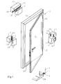
- the building closure shown in Fig.1 is a door 10 with a frame 12 and with a door leaf 11, the Swiveling on the frame 12 via door frame straps 10 ' is attached.
- the frame 12 consists of an upper Frame spar, to which two vertical frame spars connect, which have a threshold 24 between them below.
- the Wing 11 has a door leaf that is inside in the usual way a casement can be arranged and attached.
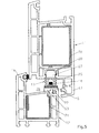
- Fig.2 shows the frame 12 and the wing 11 with in Section wing wing and frame cross sections shown.
- the spars are arranged essentially in one plane.
- frame flaps 16 and wing flaps 17 available, of which two each one Fold space 28 overlap that between the facing each other Faces of the spars.
- wing 11 and the frame 12 are made of rubber-elastic Sealing profiles 13 sealed against each other.
- Fig. 1 shows double seals. Both on the frame rollovers 16, as well as on the wing flaps 17, except for the area of threshold 24, double seals available. This is also shown in Fig. 2, for example.
- Each of the seals shown in Fig.2 has except a sealing profile 13 magnetic means 14 and / or magnetizable Share 15.
- second magnetic means 14 'and / or second magnetizable parts 15 'available are second magnetic means 14 'and / or second magnetizable parts 15 'available.
- FIG. 3 shows a greatly enlarged illustration, for example Formation of a sealing point between one Frame 12 and the wing flap 17, for example corresponding to the lower sealing points in Fig. 2.
- a sealing profile 13 the is formed with a bellows cross section 25 and one Has latching foot 27. With this locking foot 27 is the rubber elastic Seal profile 13 buttoned into a seal retaining groove 18 and locked with it.
- magnetic means 14 are arranged within the sealing profile 13. These are, for example a permanent magnetic material strip from one Plastic that is mixed with magnetic particles. Such Magnetic means are flexible and can accommodate elastic movements the rubber-elastic sealing profile 13 if necessary to adjust.
- the magnetic means 14 are on a wing side Profile surface 29 of the rubber-elastic sealing profile 13 attached, e.g. by gluing.
- a magnetizable Sheet metal strips are present to the magnetic To form the field of the magnetic means 14.
- magnetizable parts 15 on the wing 11 e.g. in the form of a along the entire edge length of the wing 11 continuous sheet metal strip.
- Such magnetic means or the magnetizable parts 15 are from the magnetic means 14 tightened so that the sealing point sealed is when the wing 11 in the closed position shown is pivoted.
- FIG. 4 shows the rubber-elastic sealing profile 13 also attached to the flap 17, as in Fig.3. Also the profile design is corresponding.
- The is different Fixing the magnetizable parts 15 on the frame 12.
- a holder 23 is provided for the magnetizable parts 15, which is fixed with a foot piece 23 '.
- the foot piece 23 ' engages in a glazing bead retaining groove 22 of the frame profile of the frame 12, which is normally used for this will latch a glass retaining bar with which a glazing a wing 11 is set.
- the bracket 23 holds the magnetizable parts 15 on one edge of the as a hollow profile trained frame 12 form-fitting against stress, which result from opening movements of the wing 11 and the magnetizable parts on the magnetic means 14 looking to keep.
- Posts are made with standard elements such as with a groove 20 adjacent to the rebate space 28 in the wing 11 or a glazing bead retaining groove 22 in the frame 12.
- the groove 20 on the rebate side is used for locking one rubber-elastic sealing profile 13 by means of its locking foot 27.
- a holder 23 for magnetizable parts 15 present in the form of a bar similar to the bracket 23 anchored in FIG. 4 with a foot in the glazing bead retaining groove 22 and on which a sheet metal strip is magnetized Part 15 is glued on. There is a middle seal between the rollovers 16.17.
- FIG. 6 are also a groove 20 of the wing 11th and a glazing bead retaining groove 22 of a frame 12 for attachment used by sealants.
- a holding profile 19 installed with an L-leg Holds magnetic means 14 in the area of the flap 17.
- a closing bar 21 which the Folding space-side end face of the frame 12 covers and attached to this. The attachment can be done with the help the glazing bead retaining groove 22 take place.
- magnetic means 14 With the locking bar 21 magnetic means 14 are firmly connected, transverse to Frame level also larger dimensions of the sealant can be accommodated and thus form a structural unit, that for narrow gaps between the rollover 17 and the neighboring one Frame 12 is particularly suitable.
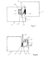
- two interacting magnetic means 14 are shown schematically, each with a rubber-elastic sealing profile 13 can be formed.
- Fig. 6 also shows schematically another sealing point in the area of Frame rollover 16.
- the sealing profile 13 has a foot 27 arranged in a spar of the wing 11, e.g. with a latch according to Fig. 5.
- the lip 26 runs essentially across the frame level, that is, in the plane of the rebate area encloses a magnetizable insert, namely magnetizable Parts e.g. in the form of magnetizable metal strips.
- the elastic lip 26 lies on the frame side, in the area from here Magnetic means 14.
- the folding room 28 is sealed against the passage of air.
- Figure 8 is a special frame profile with a vertical cross section of the groove 20 oriented to the frame plane shown, in which a foot 27 of a rubber-elastic sealing profile 13 is installed, e.g. through the illustrated Clamping.
- a V-shaped elastic lip 26 encased the magnetic means 14 with which the elastic Lip 26 adheres to magnetizable parts 15 which are on the wing 11 are attached.
- the wing 11 is open, takes the elastic lip the position shown in dashed lines and thus covers the area of the groove 20 which consequently not dirty.
- Both embodiments in Fig. 7,8 have in common that the opening of the door leaf, as in Fig. 5, for a stripping the magnetic means 14 from the magnetizable parts 15 or vice versa.
- the separation of the contiguous and to be separated from each other when opening the wing 11 Parts 14, 15 are not made transversely to these parts, but instead at least with a significant longitudinal component, which is the opening process relieved because lower opening forces are required are.
- opening the wing is manageable, if opening movements occur in the substantially perpendicular to the main planes of the magnetic means 14 or the magnetizable parts 15.
- a zipper-like opening in which the Magnetic means 14 of the magnetizable parts 15 initially pulled apart perpendicular to each other only at a single point be, whereupon a split over the length the edges of the sash or frame. This is at least obviously for the area of the upper horizontal Spars and for the area of the lower horizontal Holms of a window or for the area of a threshold a door. Otherwise, opening can also have an impact that the wing 11 and the frame 12 are not exactly parallel are arranged to each other, but have slight warpage. These contribute to the opening forces initially primarily at a preferred location or at a preferred location Area and for a local separation of the magnetic means 14 lead from the magnetizable parts 15, after which the zipper-like opening described above takes place.
- the schematic cross section shown in FIG the area of a threshold 24 shows a seal on the room side by means of two magnetic means 14, 14 ".
- the first magnetic means 14 " are in a rubber-elastic sealing profile 13 arranged, in the elastic lip 26, of which the means are enclosed.
- the profile 13 is with a Locking foot 27 locked in the wing flap 17.
- In the closed position of the wing 11 is the elastic profile against the threshold 24 drawn.
- a locking bar on the inside 32 available which with the threshold 24 e.g. by means of the illustrated rack 32 'is locked.
- the Turnover 17 facing magnet means 14 are present interact with the magnetic means 14 "of the elastic lip 26.
- Fig. 10 there is only a schematic on the interior side Sealing shown, but in the area of the rollover 17 only with magnetizable parts 15, e.g. can be attached sheet metal strips. Magnetic means 14 are available on the threshold side where there are no space problems, so that such a design especially for small distances between threshold 24 and rollover 17 suitable is.
- Fig.2 only shows for example a trap 37, which e.g. of a Strike plate of the frame engages latch opening 36 formed.
- a relative arrangement of the Wing 11, the frame 12 and the threshold 24 to each other this ensures that the rubber-elastic sealing profiles 13 the sealing position predetermined for them take, so without stressing the rubber elastic Material.
Landscapes
- Engineering & Computer Science (AREA)
- Civil Engineering (AREA)
- Structural Engineering (AREA)
- Specific Sealing Or Ventilating Devices For Doors And Windows (AREA)
Abstract
Description
- Fig. 1
- eine schematische perspektivische Darstellung eines Bauwerksabschlusses mit geöffnetem Flügel,
- Fig.2
- einen horizontalen Schnitt durch den Bauwerksabschluß gemäß Fig.1,
- Fig.3
- eine vergrößerte Schnittdarstellung durch eine Abdichtungsstelle zwischen einem Flügel und einem Blendrahmen,
- Fig.4
- eine der Fig.3 ähnliche Darstellung mit abweichender Ausgestaltung der Abdichtung,
- Fig.5
- einen Horizontalschnitt durch einen vertikalen Blendrahmenholm und einen vertikalen Flügelrahmenholm mit im Falzraum angeordneter Abdichtung,
- Fig.6
- eine der Fig.5 ähnliche Darstellung mit speziellen Befestigungen der Abdichtungsmittel,
- Fig.7,8
- schematische Darstellungen von im Falzraum angeordneten Abdichtungen unterschiedlicher Ausgestaltungen, und
- Fig.9,10
- schematische Querschnittsgestaltungen im Bereich einer Bodenschwelle.
Claims (11)
- Bauwerksabschluß, insbesondere Tür (10) oder Fenster, deren bzw. dessen öffenbarer Flügel (11) zumindest seitlich und oben am Blendrahmen (12) mit einer Magnetdichtung ringsum abgedichtet ist, dadurch gekennzeichnet, daß am Flügel (11) oder am Blendrahmen (12) gummielastisches Dichtungsprofil (13) vorhanden ist, das Magnetmittel (14) begrenzt relativbeweglich trägt, die magnetisierbare Teile (15) oder weitere Magnetmittel des Blendrahmens (12) bzw. des Flügels (11) abdichtend am Dichtungsprofil (13) halten.
- Bauwerksabschluß nach Anspruch 1, dadurch gekennzeichnet, daß die Magnetmittel (14) oder die magnetisierbaren Teile (15) am Blendrahmen- (16) und/oder am Flügelüberschlag (17) angeordnet sind.
- Bauwerksabschluß nach Anspruch 1 oder 2, dadurch gekennzeichnet, daß die Magnetmittel (14) oder die magnetisierbaren Teile (15) mit dem gummielastischen Dichtungsprofil (13) am Blendrahmen- (16) und/oder am Flügelüberschlag (17) in einer Dichtungshaltenut (18) befestigt sind.
- Bauwerksabschluß nach einem oder mehreren der Ansprüche 1 bis 3, dadurch gekennzeichnet, daß die Magnetmittel (14) oder die magnetisierbaren Teile (15) mit dem gummielastischen Dichtungsprofil (13) oder mit einem Halteprofil (19) in einer zwischen dem Blendrahmen- (16) und dem Flügelüberschlag (17) vorhandenen falzraumseitigen Nut (20) des Flügels (11) oder des Blendrahmens (13) befestigt sind.
- Bauwerksabschluß nach einem oder mehreren der Ansprüche 1 bis 4, dadurch gekennzeichnet, daß die Magnetmittel (14) oder die magnetisierbaren Teile (15) von einer am Blendrahmen (12) befestigten Schließleiste (21) oder von einer in einer Glasleistenhaltenut (22) eines Rahmenprofils festgelegten Halterung (23) gehalten sind.
- Bauwerksabschluß nach einem oder mehreren der Ansprüche 1 bis 5, dadurch gekennzeichnet, daß Magnetmittel (14) oder magnetisierbare Teile (15) am Flügel (11) oder am Blendrahmen (12) auch unten oder an einer Bodenschwelle (24) angeordnet sind.
- Bauwerksabschluß nach einem oder mehreren der Ansprüche 1 bis 6, dadurch gekennzeichnet, daß das gummielastische Dichtungsprofil (13) mit einem Faltenbalgquerschnitt (25) ausgebildet ist, in dem die Magnetmittel (14) oder die magnetisierbaren Teile (15) geschützt untergebracht sind.
- Bauwerksabschluß nach einem oder mehreren der Ansprüche 1 bis 7, dadurch gekennzeichnet, daß das gummielastische Dichtungsprofil (13) eine klappbewegliche Lippe (26) hat, in der die Magnetmittel (14) oder die magnetisierbaren Teile (15) bedarfsweise umhüllt angeordnet sind.
- Bauwerksabschluß nach einem oder mehreren der Ansprüche 1 bis 8, dadurch gekennzeichnet, daß das gummielastische Dichtungsprofil (13) mit einem Rastfuß (27) am Flügel (11) oder am Blendrahmen (12) befestigt ist.
- Bauwerksabschluß nach einem oder mehreren der Ansprüche 1 bis 9, dadurch gekennzeichnet, daß am Flügel (11), am Blendrahmen (12) oder an einer Bodenschwelle (24) zusätzlich zu einem ersten gummielastischen Dichtungsprofil (13) ein zweites gummielastisches Dichtungsprofil (13') vorhanden ist, das zweite Magnetmittel (14') begrenzt relativbeweglich trägt, die zweite magnetisierbare Teile (15') des Blendrahmens (11), des Flügels (12) bzw. einer Bodenschwelle (24) abdichtend am zweiten Dichtungsprofil (13') halten.
- Bauwerksabschluß nach einem oder mehreren der Ansprüche 1 bis 10, dadurch gekennzeichnet, daß der Flügel (11), der Blendrahmen (12) und/oder die Bodenschwelle (24) in einer relativen Schließstellung zu halten sind, in der das gummielastische Dichtungsprofil (13,13') eine vorbestimmte Abdichtstellung einnimmt.
Applications Claiming Priority (2)
| Application Number | Priority Date | Filing Date | Title |
|---|---|---|---|
| DE29816030U DE29816030U1 (de) | 1998-09-07 | 1998-09-07 | Bauwerksabschluß, insbesondere Tür oder Fenster |
| DE29816030U | 1998-09-07 |
Publications (2)
| Publication Number | Publication Date |
|---|---|
| EP0995875A2 true EP0995875A2 (de) | 2000-04-26 |
| EP0995875A3 EP0995875A3 (de) | 2001-04-25 |
Family
ID=8062305
Family Applications (1)
| Application Number | Title | Priority Date | Filing Date |
|---|---|---|---|
| EP99117611A Withdrawn EP0995875A3 (de) | 1998-09-07 | 1999-09-07 | Bauwerksabschluss, insbesondere Tür oder Fenster |
Country Status (2)
| Country | Link |
|---|---|
| EP (1) | EP0995875A3 (de) |
| DE (1) | DE29816030U1 (de) |
Cited By (3)
| Publication number | Priority date | Publication date | Assignee | Title |
|---|---|---|---|---|
| GB2482165A (en) * | 2010-07-22 | 2012-01-25 | Richard Peter Laver | Magnetic seal for a door or window |
| CN104373602A (zh) * | 2013-08-12 | 2015-02-25 | 苏州维艾普新材料股份有限公司 | 一种电场可控的磁力密封装置 |
| DE102021002464A1 (de) | 2021-05-10 | 2022-11-10 | Mercedes-Benz Group AG | Verbindungseinrichtung zum Übertragen von elektrischer Energie, insbesondere für ein Kraftfahrzeug |
Families Citing this family (3)
| Publication number | Priority date | Publication date | Assignee | Title |
|---|---|---|---|---|
| DE20217176U1 (de) * | 2002-11-07 | 2004-03-18 | Niemann, Hans Dieter | Magnetschwellendichtung |
| DE102018006108B4 (de) * | 2018-08-02 | 2022-11-03 | Marcus Pietz | System zum Einbau in eine Gebäudeöffnung |
| DE102019118822A1 (de) * | 2019-07-11 | 2021-01-14 | Andreas Wiest | Türdichtung und Tür |
Family Cites Families (10)
| Publication number | Priority date | Publication date | Assignee | Title |
|---|---|---|---|---|
| DE7438033U (de) * | 1975-03-13 | Isenegger B | Flügeldichtu ngsvorrichtung, insbesondere für Türen und Fenster | |
| DE839360C (de) * | 1949-10-22 | 1952-05-19 | Gen Electric | Einrichtung zum Verschluss und zur Abdichtung von OEffnungen, beispielsweise von Schraenken |
| DE1830986U (de) * | 1960-12-05 | 1961-05-10 | Licentia Gmbh | Vorrichtung zum abdichten und verschliessen einer teur oder einer klappe. |
| CH436661A (de) * | 1966-06-08 | 1967-05-31 | Isenegger Bernhard | Flügeldichtungsvorrichtung, insbesondere für Türen und Fenster |
| GB1554941A (en) * | 1976-04-09 | 1979-10-31 | Schlegel Uk Ltd | Extruded sealing strip |
| GB8424683D0 (en) * | 1984-10-01 | 1984-11-07 | Shapland & Petter Ltd | Smoke-prevention doors and panels |
| IT8521837U1 (it) * | 1985-05-17 | 1986-11-17 | Ilpea Spa | Guarnizione per serramenti, quali porte e finestre, atta ad operare in posizione di chiusura una tenuta tra le parti esterne ed interne del serramento |
| IT207427Z2 (it) * | 1986-05-13 | 1988-01-18 | Ilpea Spa | Guarnizione per serramenti, quali porte e finestre a libro "tipo veranda", atta ad operare in posizione di chiusura una tenuta tra le parti esterne ed interne del serramento. |
| DE8911833U1 (de) * | 1989-10-04 | 1990-04-19 | eurAl Firmengruppe für Fenster- und Türensysteme GmbH, 3167 Burgdorf | Tür, Fenster od. dgl. |
| GB2276409B (en) * | 1993-03-23 | 1996-05-15 | Antoni Harold Nikolas Gontar | Shower doors |
-
1998
- 1998-09-07 DE DE29816030U patent/DE29816030U1/de not_active Expired - Lifetime
-
1999
- 1999-09-07 EP EP99117611A patent/EP0995875A3/de not_active Withdrawn
Cited By (3)
| Publication number | Priority date | Publication date | Assignee | Title |
|---|---|---|---|---|
| GB2482165A (en) * | 2010-07-22 | 2012-01-25 | Richard Peter Laver | Magnetic seal for a door or window |
| CN104373602A (zh) * | 2013-08-12 | 2015-02-25 | 苏州维艾普新材料股份有限公司 | 一种电场可控的磁力密封装置 |
| DE102021002464A1 (de) | 2021-05-10 | 2022-11-10 | Mercedes-Benz Group AG | Verbindungseinrichtung zum Übertragen von elektrischer Energie, insbesondere für ein Kraftfahrzeug |
Also Published As
| Publication number | Publication date |
|---|---|
| DE29816030U1 (de) | 2000-01-20 |
| EP0995875A3 (de) | 2001-04-25 |
Similar Documents
| Publication | Publication Date | Title |
|---|---|---|
| EP0841456B1 (de) | Lamellenfenster für im wesentlichen senkrechte Fassaden | |
| EP0312791A2 (de) | Dichtungsprofil aus Gummi oder gummiähnlichem Kunststoff | |
| DE202022100517U1 (de) | Profilanordnung eines Fensters oder einer Tür mit einem Flügelprofil, insbesondere einem Schiebeflügelprofil | |
| DE2037517A1 (de) | Rahmenloses Fenster oder Tür | |
| EP0298354B1 (de) | Kunststoffrahmen für Fenster, Türen od. dgl. | |
| DE29816030U1 (de) | Bauwerksabschluß, insbesondere Tür oder Fenster | |
| DE202004004686U1 (de) | Schließblech für Fenster oder Fenstertüren | |
| CH714559B1 (de) | Bauelement zum Verschliessen einer Öffnung in einem Bauwerk, insbesondere Fensterelement. | |
| DE102011114361A1 (de) | Insektenschutzvorrichtung | |
| EP0833998A1 (de) | Fensterflügelrahmen-hohlprofil und daraus bestehender doppelflügel-fensterrahmen | |
| EP4047169B1 (de) | Dichtung für eine tür, insbesondere für eine zweiflügelige tür | |
| DE3150029C2 (de) | Treibstangenverschluß mit Eckumlenkung für Fenster und Türen od.dgl. | |
| EP0945579A2 (de) | Lüftungseinrichtung | |
| DE69612538T2 (de) | Flügelrahmen für Doppelflügelfenster | |
| DE202018101839U1 (de) | Türflügel mit Dichtungssystem | |
| DE29709259U1 (de) | Flügeleinheit | |
| DE2511331B2 (de) | Druckausgleichstuer | |
| DE29618315U1 (de) | Fenster oder Türen mit Verglasung | |
| DE102004039080B4 (de) | Dichtungsanordnung | |
| DE102004011878A1 (de) | Fenster oder Tür | |
| DE10005074C2 (de) | Einrichtung zur Anordnung in einem Spalt zwischen einem Rahmen und einem Flügel | |
| EP1116847B1 (de) | Fenster oder Tür | |
| EP2261453B1 (de) | Fenster oder Tür | |
| DE102019118822A1 (de) | Türdichtung und Tür | |
| DE202025100919U1 (de) | Vorrichtung zur Abdeckung eines Schiebeflügels, Falt-Schiebeflügels oder verschiebbaren Hebe-Schiebeflügels eines Fensters oder einer Tür |
Legal Events
| Date | Code | Title | Description |
|---|---|---|---|
| PUAI | Public reference made under article 153(3) epc to a published international application that has entered the european phase |
Free format text: ORIGINAL CODE: 0009012 |
|
| AK | Designated contracting states |
Kind code of ref document: A2 Designated state(s): AT BE CH CY DE DK ES FI FR GB GR IE IT LI LU MC NL PT SE |
|
| AX | Request for extension of the european patent |
Free format text: AL;LT;LV;MK;RO;SI |
|
| PUAL | Search report despatched |
Free format text: ORIGINAL CODE: 0009013 |
|
| AK | Designated contracting states |
Kind code of ref document: A3 Designated state(s): AT BE CH CY DE DK ES FI FR GB GR IE IT LI LU MC NL PT SE |
|
| AX | Request for extension of the european patent |
Free format text: AL;LT;LV;MK;RO;SI |
|
| AKX | Designation fees paid |
Free format text: AT BE CH CY DE DK ES FI FR GB GR IE IT LI LU MC NL PT SE |
|
| STAA | Information on the status of an ep patent application or granted ep patent |
Free format text: STATUS: THE APPLICATION IS DEEMED TO BE WITHDRAWN |
|
| 18D | Application deemed to be withdrawn |
Effective date: 20011026 |