EP0995914A2 - Befestigungselement aus Metall mit Innengewinde für die Durchsteckmontage - Google Patents
Befestigungselement aus Metall mit Innengewinde für die Durchsteckmontage Download PDFInfo
- Publication number
- EP0995914A2 EP0995914A2 EP99120761A EP99120761A EP0995914A2 EP 0995914 A2 EP0995914 A2 EP 0995914A2 EP 99120761 A EP99120761 A EP 99120761A EP 99120761 A EP99120761 A EP 99120761A EP 0995914 A2 EP0995914 A2 EP 0995914A2
- Authority
- EP
- European Patent Office
- Prior art keywords
- screw
- base body
- fastening
- mounting
- expansion
- Prior art date
- Legal status (The legal status is an assumption and is not a legal conclusion. Google has not performed a legal analysis and makes no representation as to the accuracy of the status listed.)
- Granted
Links
- 239000002184 metal Substances 0.000 title claims abstract description 5
- 229920003023 plastic Polymers 0.000 claims abstract description 4
- 239000004033 plastic Substances 0.000 claims abstract description 4
- 238000005553 drilling Methods 0.000 abstract description 3
- 230000006835 compression Effects 0.000 description 3
- 238000007906 compression Methods 0.000 description 3
- 230000015572 biosynthetic process Effects 0.000 description 2
- 238000006073 displacement reaction Methods 0.000 description 2
- 238000004873 anchoring Methods 0.000 description 1
- 238000009434 installation Methods 0.000 description 1
- 238000012423 maintenance Methods 0.000 description 1
- 238000005259 measurement Methods 0.000 description 1
Images

Classifications
-
- F—MECHANICAL ENGINEERING; LIGHTING; HEATING; WEAPONS; BLASTING
- F16—ENGINEERING ELEMENTS AND UNITS; GENERAL MEASURES FOR PRODUCING AND MAINTAINING EFFECTIVE FUNCTIONING OF MACHINES OR INSTALLATIONS; THERMAL INSULATION IN GENERAL
- F16B—DEVICES FOR FASTENING OR SECURING CONSTRUCTIONAL ELEMENTS OR MACHINE PARTS TOGETHER, e.g. NAILS, BOLTS, CIRCLIPS, CLAMPS, CLIPS OR WEDGES; JOINTS OR JOINTING
- F16B13/00—Dowels or other devices fastened in walls or the like by inserting them in holes made therein for that purpose
- F16B13/04—Dowels or other devices fastened in walls or the like by inserting them in holes made therein for that purpose with parts gripping in the hole or behind the reverse side of the wall after inserting from the front
- F16B13/045—Dowels or other devices fastened in walls or the like by inserting them in holes made therein for that purpose with parts gripping in the hole or behind the reverse side of the wall after inserting from the front having axially compressing parts allowing the clamping of an object tightly to the wall
-
- F—MECHANICAL ENGINEERING; LIGHTING; HEATING; WEAPONS; BLASTING
- F16—ENGINEERING ELEMENTS AND UNITS; GENERAL MEASURES FOR PRODUCING AND MAINTAINING EFFECTIVE FUNCTIONING OF MACHINES OR INSTALLATIONS; THERMAL INSULATION IN GENERAL
- F16B—DEVICES FOR FASTENING OR SECURING CONSTRUCTIONAL ELEMENTS OR MACHINE PARTS TOGETHER, e.g. NAILS, BOLTS, CIRCLIPS, CLAMPS, CLIPS OR WEDGES; JOINTS OR JOINTING
- F16B13/00—Dowels or other devices fastened in walls or the like by inserting them in holes made therein for that purpose
- F16B13/12—Separate metal or non-separate or non-metal dowel sleeves fastened by inserting the screw, nail or the like
- F16B13/124—Separate metal or non-separate or non-metal dowel sleeves fastened by inserting the screw, nail or the like fastened by inserting a threaded element, e.g. screw or bolt
Definitions
- the invention relates to a fastening element made of metal with a in the borehole Component anchored base body and one in an internal thread of the base body screw-in screw according to the preamble of claim 1.
- Such fasteners referred to as impact anchors are general known. They consist of a metal sleeve starting from their front end are slotted over part of their length. Tapered towards the front end the inner bore of the sleeve, so that by driving in an expansion body in the tapered inner bore, the expansion of the sleeve and thus its Anchored in a borehole. A is used to drive in the expansion body Setting tool used, the mandrel fits through the internal threaded hole.
- the screw After anchoring, the screw is used to fasten an object inserted through the mounting hole of the object and into the internal thread screwed into the impact anchor.
- the diameter of the mounting hole in the item to be attached adjusted to the outside diameter of the screw.
- Such an assembly requires an exact measurement of the attachment points and careful preparation of the drill holes, while drilling through the fastening points through the holes in the object to be fastened.
- the invention is therefore based on the object of having a fastening element To create internal thread for push-through installation, without a special Setting tool enables quick and easy assembly and by spreading is suitable for the train zone.
- the element corresponding to the object to be fastened becomes the fastening of an object in push-through assembly.
- the holes in the component for inserting the Fasteners created and then the fasteners with the in the Base screwed screw until the screw head rests the object to be fastened.
- the base body moves axially towards the screw head, whereby the deformable element is compressed.
- the axial displacement of the base body simultaneously becomes that on the base body Arranged expansion cone in the expansion clip that is immovable in the borehole retracted and anchored the fastener in the hole of the component.
- the deformable element is a plastic bushing with a reduced one in the central area Cross section formed. This achieves a high compressibility, which ensures that there is sufficient displacement for the base body to expand of the expansion clip is available.
- To center the fastener at it is the assembly in the borehole of the component and fastening object expedient to provide a centering collar at each of the two ends of the socket.
- the inner surface of the socket with ribs. This ensures that when the screw is loosened, the bush remains on the screw and when the object is reattached, the screw with the deformable Element can be re-used pre-assembled.
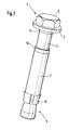
- the fastening element 10 consists of a screw 1 a hexagon head 2 and a base body 7, which at its front end has a spreading area 5.
- This spreading area 5 is reduced by a Section 11 formed, which is followed by an expansion cone 8, and one Spreading clip 16, which is arranged on the reduced portion 11. So that the Spreading clip 16 sets in the borehole, are projections 9 on its outer surfaces arranged.
- An internal thread is located at the rear end of the base body 7 19, which extends over part of the length of the base body.
- a deformable element 4 arranged, which preferably consists of plastic and is designed as a socket.
- the diameter of the outer diameter of the Basic body 7 corresponds. This results in a reduced cross section of the socket 4 in its middle area.
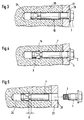
- the assembly of the fastener 10 shown in Figure 3-5 takes place in the Way that after making a bore 24 in the component 25, for example Drill through the fastening holes 26 of the object 22 to be fastened the fastener 10 completely pre-assembled in the hole 24 to the system the washer 3 is inserted into the borehole.
- the Screw 1 By turning the Screw 1 into the internal thread 19 of the base body 7, this is axially in Moved towards the screw head 2 and at the same time the expansion cone 8 in the Spreading pin 16 drawn in for its radial expansion.
- the socket 4 is compressed.
Landscapes
- Engineering & Computer Science (AREA)
- General Engineering & Computer Science (AREA)
- Mechanical Engineering (AREA)
- Dowels (AREA)
- Connection Of Plates (AREA)
- Bolts, Nuts, And Washers (AREA)
- Joining Of Building Structures In Genera (AREA)
Abstract
Description
- Figur 1
- die Einzelteile des Befestigungselements;
- Figur 2
- das komplettierte Befestigungselement im Einbauzustand;
- Figur 3, 4 und 5
- Montage und Demontage mit dem Befestigungselement nach Figur 1.
Claims (4)
- Befestigungselement (10) aus Metall bestehend aus einem in einem Bohrloch eines Bauteils verankerbaren Grundkörper (7) mit einem Spreizbereich (5) und einem Innengewinde (19), sowie einer in das Innengewinde (19) einschraubbaren Schraube (1), dadurch gekennzeichnet, dass auf der Schraube (1) ein verformbares Element (4) angeordnet ist, und dass die Länge des verformbaren Elements (4) mindestens der Dicke eines zu befestigenden Gegenstandes (22) entspricht.
- Befestigungselement nach Anspruch 1, dadurch gekennzeichnet, dass das verformbare Element (4) eine aus Kunststoff bestehende Buchse mit einem im Mittelbereich reduzierten Querschnitt ist.
- Befestigungselement nach Anspruch 2, dadurch gekennzeichnet, dass die Innenfläche der Buchse (4) mit Rippen (17) versehen ist.
- Befestigungselement nach Anspruch 2, dadurch gekennzeichnet, dass die Buchse (4) an ihren beiden Enden jeweils einen Zentrierbund (14,15) aufweist.
Applications Claiming Priority (2)
| Application Number | Priority Date | Filing Date | Title |
|---|---|---|---|
| DE19848931A DE19848931A1 (de) | 1998-10-23 | 1998-10-23 | Befestigungselement aus Metall mit Innengewinde für die Durchsteckmontage |
| DE19848931 | 1998-10-23 |
Publications (3)
| Publication Number | Publication Date |
|---|---|
| EP0995914A2 true EP0995914A2 (de) | 2000-04-26 |
| EP0995914A3 EP0995914A3 (de) | 2001-12-05 |
| EP0995914B1 EP0995914B1 (de) | 2006-06-07 |
Family
ID=7885421
Family Applications (1)
| Application Number | Title | Priority Date | Filing Date |
|---|---|---|---|
| EP99120761A Expired - Lifetime EP0995914B1 (de) | 1998-10-23 | 1999-10-20 | Befestigungselement aus Metall mit Innengewinde für die Durchsteckmontage |
Country Status (3)
| Country | Link |
|---|---|
| EP (1) | EP0995914B1 (de) |
| AT (1) | ATE329164T1 (de) |
| DE (2) | DE19848931A1 (de) |
Cited By (4)
| Publication number | Priority date | Publication date | Assignee | Title |
|---|---|---|---|---|
| DE20303806U1 (de) * | 2003-03-11 | 2004-07-22 | Fischerwerke Artur Fischer Gmbh & Co. Kg | Spreizanker aus Metall |
| WO2010069462A1 (de) | 2008-12-18 | 2010-06-24 | Fischerwerke Gmbh & Co. Kg | Dämpfungsvorrichtung |
| CN106563732A (zh) * | 2016-10-08 | 2017-04-19 | 杭州斯泰新材料技术有限公司 | 一种抗热胀作用的背栓及制造方法 |
| US20210317858A1 (en) * | 2018-10-09 | 2021-10-14 | Hilti Aktiengesellschaft | Expansion anchor with bulged zone |
Families Citing this family (1)
| Publication number | Priority date | Publication date | Assignee | Title |
|---|---|---|---|---|
| DE102006031467A1 (de) * | 2006-07-07 | 2008-01-10 | Fischerwerke Artur Fischer Gmbh & Co. Kg | Spreizanker |
Family Cites Families (9)
| Publication number | Priority date | Publication date | Assignee | Title |
|---|---|---|---|---|
| DD39474A (de) * | ||||
| NL43544C (de) * | 1932-11-08 | |||
| US3283641A (en) * | 1964-06-04 | 1966-11-08 | John B Wagner | Soft screw anchor |
| FR1585768A (de) * | 1968-04-15 | 1970-01-30 | ||
| ZA714672B (en) * | 1970-07-31 | 1972-04-26 | Omark Industries Inc | Improved masonry anchor |
| DE2150572A1 (de) * | 1971-10-11 | 1973-04-19 | Willi Schober | Spreizduebel |
| DE2536136A1 (de) * | 1975-08-13 | 1977-03-03 | Hilti Ag | Spreizduebel |
| DE2536137C2 (de) * | 1975-08-13 | 1986-04-10 | Hilti Ag, Schaan | Spreizdübel |
| DE3004622A1 (de) * | 1980-02-08 | 1981-08-13 | Stumpp + Kurz Gmbh + Co, 7000 Stuttgart | Duebel fuer hohlkoerpermauerwerk |
-
1998
- 1998-10-23 DE DE19848931A patent/DE19848931A1/de not_active Withdrawn
-
1999
- 1999-10-20 AT AT99120761T patent/ATE329164T1/de not_active IP Right Cessation
- 1999-10-20 DE DE59913513T patent/DE59913513D1/de not_active Expired - Fee Related
- 1999-10-20 EP EP99120761A patent/EP0995914B1/de not_active Expired - Lifetime
Non-Patent Citations (1)
| Title |
|---|
| None |
Cited By (7)
| Publication number | Priority date | Publication date | Assignee | Title |
|---|---|---|---|---|
| DE20303806U1 (de) * | 2003-03-11 | 2004-07-22 | Fischerwerke Artur Fischer Gmbh & Co. Kg | Spreizanker aus Metall |
| WO2004081393A1 (de) * | 2003-03-11 | 2004-09-23 | Fischerwerke Artur Fischer Gmbh & Co. Kg | Spreizanker aus metall |
| CN100436840C (zh) * | 2003-03-11 | 2008-11-26 | 费希尔厂有限责任两合公司 | 金属制可膨胀锚栓 |
| WO2010069462A1 (de) | 2008-12-18 | 2010-06-24 | Fischerwerke Gmbh & Co. Kg | Dämpfungsvorrichtung |
| EP2368050B1 (de) * | 2008-12-18 | 2016-04-27 | fischerwerke GmbH & Co. KG | Dämpfungsvorrichtung |
| CN106563732A (zh) * | 2016-10-08 | 2017-04-19 | 杭州斯泰新材料技术有限公司 | 一种抗热胀作用的背栓及制造方法 |
| US20210317858A1 (en) * | 2018-10-09 | 2021-10-14 | Hilti Aktiengesellschaft | Expansion anchor with bulged zone |
Also Published As
| Publication number | Publication date |
|---|---|
| EP0995914A3 (de) | 2001-12-05 |
| EP0995914B1 (de) | 2006-06-07 |
| DE59913513D1 (de) | 2006-07-20 |
| ATE329164T1 (de) | 2006-06-15 |
| DE19848931A1 (de) | 2000-04-27 |
Similar Documents
| Publication | Publication Date | Title |
|---|---|---|
| EP0499580B1 (de) | Ausziehwerkzeug | |
| DE2458317A1 (de) | Spreizduebel | |
| EP0314912B1 (de) | Spreizdübel für die Verankerung in hinterschnittenen Bohrlöchern | |
| DE2547634A1 (de) | Sicherheitsduebel | |
| DE4030978A1 (de) | Verbindungseinrichtung fuer ein insbesondere rohrfoermiges bauteil | |
| EP0564889A1 (de) | Verbindungseinrichtung für ein insbesondere rohrförmiges Bauteil | |
| DE19936090A1 (de) | Befestigungselement aus Metall | |
| DE4210488A1 (de) | Verbindungseinrichtung für ein insbesondere rohrförmiges Bauteil | |
| EP1277972B1 (de) | Spreizdübel | |
| EP0728882B1 (de) | Befestigungselement zum Befestigen von Platten grosser Dicke an Bauteilen | |
| EP0995914B1 (de) | Befestigungselement aus Metall mit Innengewinde für die Durchsteckmontage | |
| EP0724085A1 (de) | Formschlüssig setzbarer Hinterschnitt-Anker | |
| DE102011002031A1 (de) | Verankerungseinrichtung zum Befestigen eines Bauteils an einem Trägerelement | |
| EP0908634B1 (de) | Einschlagdübel | |
| EP0381678B1 (de) | Hinterschnitt-bohrdübel | |
| EP0279936B1 (de) | Dübel mit Spreizhülse | |
| DE3220483A1 (de) | Befestigungselement | |
| DE19912068B4 (de) | Wellen- oder Stellmutter und Verfahren zu ihrer Herstellung | |
| EP1611361B1 (de) | Spreizanker aus Metall | |
| EP1201944A1 (de) | Verbindungselement | |
| DE3620573A1 (de) | Vorrichtung zum befestigen eines gegenstandes an einer wand oder dgl. | |
| DE3447414C2 (de) | ||
| DD267536A5 (de) | Duebel mit spreizhuelse | |
| EP0808426B1 (de) | Befestigungseinrichtung in einem nicht durchgehenden hinterschnittenen bohrloch | |
| EP0940587A2 (de) | Befestigungsvorrichtung |
Legal Events
| Date | Code | Title | Description |
|---|---|---|---|
| PUAI | Public reference made under article 153(3) epc to a published international application that has entered the european phase |
Free format text: ORIGINAL CODE: 0009012 |
|
| AK | Designated contracting states |
Kind code of ref document: A2 Designated state(s): AT BE CH CY DE DK ES FI FR GB GR IE IT LI LU MC NL PT SE |
|
| AX | Request for extension of the european patent |
Free format text: AL;LT;LV;MK;RO;SI |
|
| PUAL | Search report despatched |
Free format text: ORIGINAL CODE: 0009013 |
|
| AK | Designated contracting states |
Kind code of ref document: A3 Designated state(s): AT BE CH CY DE DK ES FI FR GB GR IE IT LI LU MC NL PT SE |
|
| AX | Request for extension of the european patent |
Free format text: AL;LT;LV;MK;RO;SI |
|
| RIC1 | Information provided on ipc code assigned before grant |
Free format text: 7F 16B 13/10 A, 7F 16B 13/06 B, 7F 16B 13/04 B |
|
| 17P | Request for examination filed |
Effective date: 20020423 |
|
| AKX | Designation fees paid |
Free format text: AT BE CH CY DE DK ES FI FR GB GR IE IT LI LU MC NL PT SE |
|
| 17Q | First examination report despatched |
Effective date: 20050503 |
|
| GRAP | Despatch of communication of intention to grant a patent |
Free format text: ORIGINAL CODE: EPIDOSNIGR1 |
|
| GRAS | Grant fee paid |
Free format text: ORIGINAL CODE: EPIDOSNIGR3 |
|
| GRAA | (expected) grant |
Free format text: ORIGINAL CODE: 0009210 |
|
| AK | Designated contracting states |
Kind code of ref document: B1 Designated state(s): AT BE CH CY DE DK ES FI FR GB GR IE IT LI LU MC NL PT SE |
|
| PG25 | Lapsed in a contracting state [announced via postgrant information from national office to epo] |
Ref country code: IT Free format text: LAPSE BECAUSE OF FAILURE TO SUBMIT A TRANSLATION OF THE DESCRIPTION OR TO PAY THE FEE WITHIN THE PRESCRIBED TIME-LIMIT;WARNING: LAPSES OF ITALIAN PATENTS WITH EFFECTIVE DATE BEFORE 2007 MAY HAVE OCCURRED AT ANY TIME BEFORE 2007. THE CORRECT EFFECTIVE DATE MAY BE DIFFERENT FROM THE ONE RECORDED. Effective date: 20060607 Ref country code: IE Free format text: LAPSE BECAUSE OF FAILURE TO SUBMIT A TRANSLATION OF THE DESCRIPTION OR TO PAY THE FEE WITHIN THE PRESCRIBED TIME-LIMIT Effective date: 20060607 Ref country code: FI Free format text: LAPSE BECAUSE OF FAILURE TO SUBMIT A TRANSLATION OF THE DESCRIPTION OR TO PAY THE FEE WITHIN THE PRESCRIBED TIME-LIMIT Effective date: 20060607 |
|
| REG | Reference to a national code |
Ref country code: GB Ref legal event code: FG4D Free format text: NOT ENGLISH |
|
| REG | Reference to a national code |
Ref country code: CH Ref legal event code: EP |
|
| REG | Reference to a national code |
Ref country code: IE Ref legal event code: FG4D Free format text: LANGUAGE OF EP DOCUMENT: GERMAN |
|
| REF | Corresponds to: |
Ref document number: 59913513 Country of ref document: DE Date of ref document: 20060720 Kind code of ref document: P |
|
| PG25 | Lapsed in a contracting state [announced via postgrant information from national office to epo] |
Ref country code: SE Free format text: LAPSE BECAUSE OF FAILURE TO SUBMIT A TRANSLATION OF THE DESCRIPTION OR TO PAY THE FEE WITHIN THE PRESCRIBED TIME-LIMIT Effective date: 20060907 Ref country code: DK Free format text: LAPSE BECAUSE OF FAILURE TO SUBMIT A TRANSLATION OF THE DESCRIPTION OR TO PAY THE FEE WITHIN THE PRESCRIBED TIME-LIMIT Effective date: 20060907 |
|
| PG25 | Lapsed in a contracting state [announced via postgrant information from national office to epo] |
Ref country code: ES Free format text: LAPSE BECAUSE OF FAILURE TO SUBMIT A TRANSLATION OF THE DESCRIPTION OR TO PAY THE FEE WITHIN THE PRESCRIBED TIME-LIMIT Effective date: 20060918 |
|
| PGFP | Annual fee paid to national office [announced via postgrant information from national office to epo] |
Ref country code: NL Payment date: 20061003 Year of fee payment: 8 |
|
| PGFP | Annual fee paid to national office [announced via postgrant information from national office to epo] |
Ref country code: AT Payment date: 20061011 Year of fee payment: 8 |
|
| PGFP | Annual fee paid to national office [announced via postgrant information from national office to epo] |
Ref country code: CH Payment date: 20061013 Year of fee payment: 8 |
|
| GBT | Gb: translation of ep patent filed (gb section 77(6)(a)/1977) |
Effective date: 20060925 |
|
| PGFP | Annual fee paid to national office [announced via postgrant information from national office to epo] |
Ref country code: GB Payment date: 20061018 Year of fee payment: 8 |
|
| ET | Fr: translation filed | ||
| PG25 | Lapsed in a contracting state [announced via postgrant information from national office to epo] |
Ref country code: MC Free format text: LAPSE BECAUSE OF NON-PAYMENT OF DUE FEES Effective date: 20061031 |
|
| PGFP | Annual fee paid to national office [announced via postgrant information from national office to epo] |
Ref country code: IT Payment date: 20061031 Year of fee payment: 8 |
|
| PG25 | Lapsed in a contracting state [announced via postgrant information from national office to epo] |
Ref country code: PT Free format text: LAPSE BECAUSE OF FAILURE TO SUBMIT A TRANSLATION OF THE DESCRIPTION OR TO PAY THE FEE WITHIN THE PRESCRIBED TIME-LIMIT Effective date: 20061107 |
|
| REG | Reference to a national code |
Ref country code: IE Ref legal event code: FD4D |
|
| PLBE | No opposition filed within time limit |
Free format text: ORIGINAL CODE: 0009261 |
|
| STAA | Information on the status of an ep patent application or granted ep patent |
Free format text: STATUS: NO OPPOSITION FILED WITHIN TIME LIMIT |
|
| 26N | No opposition filed |
Effective date: 20070308 |
|
| BERE | Be: lapsed |
Owner name: FISCHERWERKE ARTUR FISCHER G.M.B.H. & CO. KG Effective date: 20061031 |
|
| PGFP | Annual fee paid to national office [announced via postgrant information from national office to epo] |
Ref country code: DE Payment date: 20070801 Year of fee payment: 9 |
|
| PG25 | Lapsed in a contracting state [announced via postgrant information from national office to epo] |
Ref country code: GR Free format text: LAPSE BECAUSE OF FAILURE TO SUBMIT A TRANSLATION OF THE DESCRIPTION OR TO PAY THE FEE WITHIN THE PRESCRIBED TIME-LIMIT Effective date: 20060908 |
|
| GBPC | Gb: european patent ceased through non-payment of renewal fee |
Effective date: 20071020 |
|
| REG | Reference to a national code |
Ref country code: CH Ref legal event code: PL |
|
| NLV4 | Nl: lapsed or anulled due to non-payment of the annual fee |
Effective date: 20080501 |
|
| PG25 | Lapsed in a contracting state [announced via postgrant information from national office to epo] |
Ref country code: LU Free format text: LAPSE BECAUSE OF NON-PAYMENT OF DUE FEES Effective date: 20061020 Ref country code: LI Free format text: LAPSE BECAUSE OF NON-PAYMENT OF DUE FEES Effective date: 20071031 Ref country code: CH Free format text: LAPSE BECAUSE OF NON-PAYMENT OF DUE FEES Effective date: 20071031 |
|
| PG25 | Lapsed in a contracting state [announced via postgrant information from national office to epo] |
Ref country code: AT Free format text: LAPSE BECAUSE OF NON-PAYMENT OF DUE FEES Effective date: 20071020 |
|
| REG | Reference to a national code |
Ref country code: FR Ref legal event code: ST Effective date: 20080630 |
|
| PG25 | Lapsed in a contracting state [announced via postgrant information from national office to epo] |
Ref country code: NL Free format text: LAPSE BECAUSE OF NON-PAYMENT OF DUE FEES Effective date: 20080501 |
|
| PGFP | Annual fee paid to national office [announced via postgrant information from national office to epo] |
Ref country code: FR Payment date: 20061010 Year of fee payment: 8 |
|
| PG25 | Lapsed in a contracting state [announced via postgrant information from national office to epo] |
Ref country code: GB Free format text: LAPSE BECAUSE OF NON-PAYMENT OF DUE FEES Effective date: 20071020 Ref country code: CY Free format text: LAPSE BECAUSE OF FAILURE TO SUBMIT A TRANSLATION OF THE DESCRIPTION OR TO PAY THE FEE WITHIN THE PRESCRIBED TIME-LIMIT Effective date: 20060607 |
|
| PG25 | Lapsed in a contracting state [announced via postgrant information from national office to epo] |
Ref country code: FR Free format text: LAPSE BECAUSE OF NON-PAYMENT OF DUE FEES Effective date: 20071031 |
|
| PG25 | Lapsed in a contracting state [announced via postgrant information from national office to epo] |
Ref country code: IT Free format text: LAPSE BECAUSE OF NON-PAYMENT OF DUE FEES Effective date: 20071020 Ref country code: DE Free format text: LAPSE BECAUSE OF NON-PAYMENT OF DUE FEES Effective date: 20090501 Ref country code: BE Free format text: LAPSE BECAUSE OF FAILURE TO SUBMIT A TRANSLATION OF THE DESCRIPTION OR TO PAY THE FEE WITHIN THE PRESCRIBED TIME-LIMIT Effective date: 20061031 |