EP0995919B1 - Etrier de frein pour frein à disque à garnitures partielles - Google Patents
Etrier de frein pour frein à disque à garnitures partielles Download PDFInfo
- Publication number
- EP0995919B1 EP0995919B1 EP19990116497 EP99116497A EP0995919B1 EP 0995919 B1 EP0995919 B1 EP 0995919B1 EP 19990116497 EP19990116497 EP 19990116497 EP 99116497 A EP99116497 A EP 99116497A EP 0995919 B1 EP0995919 B1 EP 0995919B1
- Authority
- EP
- European Patent Office
- Prior art keywords
- brake
- brake calliper
- calliper
- forming
- moulded parts
- Prior art date
- Legal status (The legal status is an assumption and is not a legal conclusion. Google has not performed a legal analysis and makes no representation as to the accuracy of the status listed.)
- Expired - Lifetime
Links
Images

Classifications
-
- F—MECHANICAL ENGINEERING; LIGHTING; HEATING; WEAPONS; BLASTING
- F16—ENGINEERING ELEMENTS AND UNITS; GENERAL MEASURES FOR PRODUCING AND MAINTAINING EFFECTIVE FUNCTIONING OF MACHINES OR INSTALLATIONS; THERMAL INSULATION IN GENERAL
- F16D—COUPLINGS FOR TRANSMITTING ROTATION; CLUTCHES; BRAKES
- F16D55/00—Brakes with substantially-radial braking surfaces pressed together in axial direction, e.g. disc brakes
- F16D55/02—Brakes with substantially-radial braking surfaces pressed together in axial direction, e.g. disc brakes with axially-movable discs or pads pressed against axially-located rotating members
-
- F—MECHANICAL ENGINEERING; LIGHTING; HEATING; WEAPONS; BLASTING
- F16—ENGINEERING ELEMENTS AND UNITS; GENERAL MEASURES FOR PRODUCING AND MAINTAINING EFFECTIVE FUNCTIONING OF MACHINES OR INSTALLATIONS; THERMAL INSULATION IN GENERAL
- F16D—COUPLINGS FOR TRANSMITTING ROTATION; CLUTCHES; BRAKES
- F16D65/00—Parts or details
- F16D65/0006—Noise or vibration control
-
- F—MECHANICAL ENGINEERING; LIGHTING; HEATING; WEAPONS; BLASTING
- F16—ENGINEERING ELEMENTS AND UNITS; GENERAL MEASURES FOR PRODUCING AND MAINTAINING EFFECTIVE FUNCTIONING OF MACHINES OR INSTALLATIONS; THERMAL INSULATION IN GENERAL
- F16D—COUPLINGS FOR TRANSMITTING ROTATION; CLUTCHES; BRAKES
- F16D65/00—Parts or details
- F16D65/78—Features relating to cooling
- F16D65/84—Features relating to cooling for disc brakes
-
- F—MECHANICAL ENGINEERING; LIGHTING; HEATING; WEAPONS; BLASTING
- F16—ENGINEERING ELEMENTS AND UNITS; GENERAL MEASURES FOR PRODUCING AND MAINTAINING EFFECTIVE FUNCTIONING OF MACHINES OR INSTALLATIONS; THERMAL INSULATION IN GENERAL
- F16D—COUPLINGS FOR TRANSMITTING ROTATION; CLUTCHES; BRAKES
- F16D55/00—Brakes with substantially-radial braking surfaces pressed together in axial direction, e.g. disc brakes
- F16D2055/0004—Parts or details of disc brakes
- F16D2055/0016—Brake calipers
-
- F—MECHANICAL ENGINEERING; LIGHTING; HEATING; WEAPONS; BLASTING
- F16—ENGINEERING ELEMENTS AND UNITS; GENERAL MEASURES FOR PRODUCING AND MAINTAINING EFFECTIVE FUNCTIONING OF MACHINES OR INSTALLATIONS; THERMAL INSULATION IN GENERAL
- F16D—COUPLINGS FOR TRANSMITTING ROTATION; CLUTCHES; BRAKES
- F16D55/00—Brakes with substantially-radial braking surfaces pressed together in axial direction, e.g. disc brakes
- F16D2055/0004—Parts or details of disc brakes
- F16D2055/0016—Brake calipers
- F16D2055/002—Brake calipers assembled from a plurality of parts
-
- F—MECHANICAL ENGINEERING; LIGHTING; HEATING; WEAPONS; BLASTING
- F16—ENGINEERING ELEMENTS AND UNITS; GENERAL MEASURES FOR PRODUCING AND MAINTAINING EFFECTIVE FUNCTIONING OF MACHINES OR INSTALLATIONS; THERMAL INSULATION IN GENERAL
- F16D—COUPLINGS FOR TRANSMITTING ROTATION; CLUTCHES; BRAKES
- F16D55/00—Brakes with substantially-radial braking surfaces pressed together in axial direction, e.g. disc brakes
- F16D2055/0075—Constructional features of axially engaged brakes
- F16D2055/0091—Plural actuators arranged side by side on the same side of the rotor
-
- F—MECHANICAL ENGINEERING; LIGHTING; HEATING; WEAPONS; BLASTING
- F16—ENGINEERING ELEMENTS AND UNITS; GENERAL MEASURES FOR PRODUCING AND MAINTAINING EFFECTIVE FUNCTIONING OF MACHINES OR INSTALLATIONS; THERMAL INSULATION IN GENERAL
- F16D—COUPLINGS FOR TRANSMITTING ROTATION; CLUTCHES; BRAKES
- F16D65/00—Parts or details
- F16D65/78—Features relating to cooling
- F16D2065/781—Features relating to cooling involving phase change of material
Definitions
- the innovation relates to a caliper according to the preamble of claim 1 for a part lining disc brake.
- Such a caliper is essentially known from DE-OS 44 20 652.
- the there provided, monolithically cast from a metal brake caliper is designed to improve its thermal properties as Verbundgußteil, in such a way that poured into the casting of the caliper a substantially spaced from the outside pipe for a coolant circulation, at least in its two parts forming the bridge portion is.
- Such or even a comparative equipment of a brake caliper with a coolant circuit can only lead to an improvement of the thermal properties of the caliper, if at the same time a connection to a cooling system for the coolant is present, which then indeed allows an optimization of the thermal properties of the caliper , but naturally leads to a very high total cost for the improvement alone of the thermal properties of a caliper, but at the same time also causing a significant change in the direction of improving the vibration characteristics of the caliper.
- the novelty is therefore based on the object to further develop a brake caliper in the preamble of claim 1, that at the same strength of the caliper ensures both an improvement of the vibration behavior and a reduction of the total weight and in a development also also achieves an optimization of the thermal properties is.
- the caliper consists of at least two along a parting plane by means of a joining process interconnected Gußform former, with as preferred joining method welding process into consideration, in particular Laser welding or electron-beam welding.
- a preparation of the caliper from joining technically interconnected mold parts can be used in a development also to form hollow chambers in one or the other or naturally also in both legs of the caliper or to order.
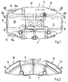
- the calipers 1 have in the usual way an at least substantially symmetrical U-shaped shape and partially surround a brake disc not shown in detail, wherein in the two legs 2 and 3 of the U-shape, the brake pads 4 and 5 are received and guided are.
- the brake pads 4 and 5 are each by means of their turn in the legs 2 and 3 arranged or recorded wheel brake cylinders 6 and 7 can be pressed against the side surfaces of the brake disc.
- the bridge part 8 of the caliper 1 consists of two access to the brake pads 4 and 5 ensuring window 9 between them enclosing bridge parts 10 and 11.
- the peripheral walls 13 are circumferentially uniformly thin-walled.
- the calipers 1 shown in the drawing are each formed as castings, wherein the brake caliper 1 shown in Figures 1 and 2 consists of two along a dividing line II-II composite molded articles 14 and 15.
- the two mold parts 14 and 15 are mirror images of each other, such that each of the two mold parts 14 and 15 each have one half of the cavities 12 forming pocket-shaped recesses and both moldings along the parting plane II-II are connected to each other by laser welding.
- one molded part 15a is provided with pocket-shaped recesses which form the main part of the cavities 12, while there is only one cover part with respect to the cavities 12 and 14a with joined parts joined together by laser welding 15a which closes the cavities 12 forming pocket-like recesses in the molded part 15a.
- cavities are likewise formed at least in the leg 2 of the brake caliper 1.
- the caliper 1 is a total of three along the two parting planes II-II or III-III and IV-IV interconnected and welded cast-molded parts 14, 15 and 17, wherein the molded part 14 is provided with the cavities forming pocket-shaped recesses and the molding 17 is formed substantially as a cover part for the provided in the molding 14 pocket-shaped recesses.
Landscapes
- Engineering & Computer Science (AREA)
- General Engineering & Computer Science (AREA)
- Mechanical Engineering (AREA)
- Braking Arrangements (AREA)
Claims (9)
- Selle de frein pour un frein à disque à garniture partielle, qui présente section transversale généralement en forme de U et qui passe en partie sur un disque de frein, des formes de réception et de guidage pour des garnitures de frein (4, 5) étant réalisées dans des côtés situés à l'intérieur des deux branches (2, 3) de la selle de frein, orientées parallèlement au disque de frein, et dans au moins l'une des deux branches (2, 3) étant réalisé ou reçu au moins un cylindre de frein de roue (6, 7), et dans sa partie de pont (8) pontant le disque de frein, une fenêtre (9) étant prévue pour le montage et la fixation de garnitures de frein, caractérisée en ce qu'au moins dans chacune des zones (10 et 11) de la partie de pont (8) de la selle de frein (1), qui relient entre elles les deux branches (2 et 3) de la forme en U de la selle de frein (1), est réalisée une cavité (12) fermée.
- Selle de frein selon la revendication 1, caractérisée en ce que les parois périphériques (13) des cavités (12), qui forment les zones de la partie de pont (8) reliant entre elles les deux branches (2 et 3) de la selle de frein (1), sont réalisées minces.
- Selle de frein selon les revendications 1 et 2, caractérisée en ce que dans le cas d'une selle de frein (19), formée dans son ensemble à partir de deux pièces moulées (14 et 15), les deux pièces moulées (14 et 15) sont reliées entre elles par un procédé d'assemblage et dans les zones, formant la partie de pont (8) de la selle de frein (1), d'au moins l'une des deux pièces moulées (14 ou 15), est réalisé un évidement formant une partie d'une cavité (12).
- Selle de frein selon les revendications 1 à 3, caractérisée en ce que la selle de frein (1) est formée par deux pièces moulées (14 et 15) reliées entre elles le long d'un plan situé dans le plan médian du disque de frein, et les évidements, formant chacun une moitié d'une cavité (12), sont réalisés dans une symétrie en miroir l'un par rapport à l'autre dans les deux pièces moulées (14 et 15).
- Selle de frein selon les revendications 1 à 3, caractérisée en ce qu'elle est formée par deux pièces moulées (14a et 15a) reliées entre elles le long d'un plan situé au moins approximativement dans le prolongement d'une face latérale du disque de frein, et les évidements formant les cavités (12) sont formés par des renfoncements de type poche dans les zones d'une pièce moulée (15a) qui forment la partie de pont (8) de la selle de frein (1).
- Selle de frein selon l'une des revendications 1 à 5, caractérisée en ce qu'outre les cavités prévues dans sa partie de pont (8) il est réalisé aussi dans au moins l'une des deux branches (2 et/ou 3) de la selle de frein (1), au moins une cavité, et la selle de frein (1) se compose au total d'au moins trois pièces moulées (14, 15, 17) reliées entre elles le long de deux plans parallèles au plan du disque de frein.
- Selle de frein selon la revendication 6, caractérisée en ce qu'un premier plan de liaison des pièces moulées formant la selle de frein (1), coupe les cavités (12) prévues dans les zones (10 et 11) formant sa partie de pont (8), et le deuxième plan de liaison se situe dans une branche (2, 3) de la selle de frein (1).
- Selle de frein selon l'une des revendications 1 à 7, caractérisée en ce qu'au moins les cavités (12) réalisées dans les zones (10 et 11) de la partie de pont de la selle de frein (1) sont remplies au moins en partie d'un matériau thermoconducteur, en particulier de sodium.
- Selle de frein selon l'une des revendications 1 à 7, caractérisé en ce qu'au moins les cavités (12), réalisées dans les zones (10 et 11) de la partie de pont de la selle de frein (1), sont remplies au moins en partie d'un matériau amortissant les oscillations.
Applications Claiming Priority (2)
| Application Number | Priority Date | Filing Date | Title |
|---|---|---|---|
| DE29818886U DE29818886U1 (de) | 1998-10-23 | 1998-10-23 | Bremssattel für eine Teilbelagscheibenbremse |
| DE29818886U | 1998-10-23 |
Publications (3)
| Publication Number | Publication Date |
|---|---|
| EP0995919A2 EP0995919A2 (fr) | 2000-04-26 |
| EP0995919A3 EP0995919A3 (fr) | 2001-03-07 |
| EP0995919B1 true EP0995919B1 (fr) | 2006-02-01 |
Family
ID=8064271
Family Applications (1)
| Application Number | Title | Priority Date | Filing Date |
|---|---|---|---|
| EP19990116497 Expired - Lifetime EP0995919B1 (fr) | 1998-10-23 | 1999-08-23 | Etrier de frein pour frein à disque à garnitures partielles |
Country Status (2)
| Country | Link |
|---|---|
| EP (1) | EP0995919B1 (fr) |
| DE (2) | DE29818886U1 (fr) |
Cited By (1)
| Publication number | Priority date | Publication date | Assignee | Title |
|---|---|---|---|---|
| US9334909B2 (en) | 2012-04-20 | 2016-05-10 | Knorr-Bremse Systeme Fuer Nutzfahrzeuge Gmbh | Disc brake for vehicles |
Families Citing this family (3)
| Publication number | Priority date | Publication date | Assignee | Title |
|---|---|---|---|---|
| DE102007023188B4 (de) * | 2007-05-18 | 2011-07-21 | Knorr-Bremse Systeme für Nutzfahrzeuge GmbH, 80809 | Mit einer seitlichen Bearbeitungsöffnung versehener Bremssattel |
| DE102016202542A1 (de) * | 2016-02-18 | 2017-08-24 | Bayerische Motoren Werke Aktiengesellschaft | Verfahren zur Herstellung eines Fahrzeugbremssattels |
| DE102022206469A1 (de) | 2022-06-27 | 2023-12-28 | Hl Mando Corporation | Mehrteiliger bremssattel mit mindestens einem hohlen abschnitt |
Family Cites Families (9)
| Publication number | Priority date | Publication date | Assignee | Title |
|---|---|---|---|---|
| DE1898308U (de) | 1964-02-05 | 1964-08-06 | Teves Kg Alfred | Gehaeuse fuer teilbelagscheibenbremsen. |
| DE3025636A1 (de) * | 1980-07-07 | 1982-02-04 | Alfred Teves Gmbh, 6000 Frankfurt | Gegossenes werkstueck |
| DE3245157A1 (de) | 1982-12-07 | 1984-06-07 | Alfred Teves Gmbh, 6000 Frankfurt | Bremssattelgehaeuse, insbesondere fuer eine teilbelag-scheibenbremse eines kraftfahrzeuges und verfahren zur herstellung des gehaeuses |
| DE3918369A1 (de) | 1989-01-31 | 1990-08-02 | Teves Gmbh Alfred | Scheibenbremse |
| GB9108297D0 (en) * | 1991-04-18 | 1991-06-05 | Gkn Sankey Ltd | Reinforced light metal article and method for its production |
| GB9305795D0 (en) | 1993-03-19 | 1993-05-05 | Automotive Products Plc | A brake disc |
| US5394963A (en) | 1993-06-18 | 1995-03-07 | The Budd Company | Composite cast brake caliper |
| DE4416815C2 (de) | 1994-05-13 | 1997-09-11 | Porsche Ag | Festsattelbremse |
| DE19652123A1 (de) * | 1996-12-14 | 1998-06-18 | Teves Gmbh Alfred | Bremssattel, insbesondere für Kraftfahrzeuge |
-
1998
- 1998-10-23 DE DE29818886U patent/DE29818886U1/de not_active Expired - Lifetime
-
1999
- 1999-08-23 EP EP19990116497 patent/EP0995919B1/fr not_active Expired - Lifetime
- 1999-08-23 DE DE59913093T patent/DE59913093D1/de not_active Expired - Lifetime
Cited By (1)
| Publication number | Priority date | Publication date | Assignee | Title |
|---|---|---|---|---|
| US9334909B2 (en) | 2012-04-20 | 2016-05-10 | Knorr-Bremse Systeme Fuer Nutzfahrzeuge Gmbh | Disc brake for vehicles |
Also Published As
| Publication number | Publication date |
|---|---|
| DE29818886U1 (de) | 1999-03-04 |
| EP0995919A3 (fr) | 2001-03-07 |
| EP0995919A2 (fr) | 2000-04-26 |
| DE59913093D1 (de) | 2006-04-13 |
Similar Documents
| Publication | Publication Date | Title |
|---|---|---|
| DE69407291T2 (de) | Aus verbundwerkstoff hergestellte bremsscheibe sowie verfahren zu deren herstellung | |
| DE3709062C2 (fr) | ||
| EP2359021B1 (fr) | Disque de frein | |
| EP2340377B1 (fr) | Agencement de disque de frein pour freins à disque | |
| EP3712459B1 (fr) | Disque de frein | |
| EP0777830B1 (fr) | Etrier pour frein a disque | |
| US6328092B1 (en) | Process and a system for connecting at least two components | |
| DE3322424C2 (fr) | ||
| DE4420652A1 (de) | Sattel für eine Scheibenbremse | |
| EP2091678A1 (fr) | Moule de coulée pour la coulée d'une pièce et utilisation de ce moule de coulée | |
| EP1322483B1 (fr) | Jante de roue coulee | |
| DE69403736T2 (de) | Verfahren und vorrichtung zur erstellung eines käfigläufers eines induktionsmotors | |
| DE102017220680B4 (de) | Solide Bremsscheibe und Herstellungsverfahren für selbige | |
| DE4212558A1 (de) | Verstaerktes leichtmetallerzeugnis und verfahren zu seiner herstellung | |
| EP1340000B1 (fr) | Procede de production d'un frein a disque, et outil de moulage de noyaux | |
| EP0995919B1 (fr) | Etrier de frein pour frein à disque à garnitures partielles | |
| DE3613191C2 (fr) | ||
| EP2100051B1 (fr) | Disque de frein pour un frein à disque | |
| EP1002602B1 (fr) | Dispositif et procédé pour la fabrication d'un bloc moteur | |
| DE102009013358A1 (de) | Bremsscheibe für ein Fahrzeug sowie Verfahren zum Herstellen einer solchen | |
| DE19735012C1 (de) | Verfahren zur Herstellung eines gegossenen Zylinderkopfes | |
| EP1500841B1 (fr) | Procédé de fabrication d'un disque de frein, en particulier d'un disque de frein d'arbre ou de roue pour véhicules de chemin de fer | |
| DE19826848C2 (de) | Leichtmetallrad für Kraftfahrzeuge | |
| EP0943059B1 (fr) | Etrier de frein, notamment pour automobiles | |
| DE102016202543A1 (de) | Verfahren zur Herstellung eines Bremssattels eines Fahrzeuges |
Legal Events
| Date | Code | Title | Description |
|---|---|---|---|
| PUAI | Public reference made under article 153(3) epc to a published international application that has entered the european phase |
Free format text: ORIGINAL CODE: 0009012 |
|
| AK | Designated contracting states |
Kind code of ref document: A2 Designated state(s): DE FR GB IT |
|
| AX | Request for extension of the european patent |
Free format text: AL;LT;LV;MK;RO;SI |
|
| PUAL | Search report despatched |
Free format text: ORIGINAL CODE: 0009013 |
|
| AK | Designated contracting states |
Kind code of ref document: A3 Designated state(s): AT BE CH CY DE DK ES FI FR GB GR IE IT LI LU MC NL PT SE |
|
| AX | Request for extension of the european patent |
Free format text: AL;LT;LV;MK;RO;SI |
|
| 17P | Request for examination filed |
Effective date: 20010907 |
|
| AKX | Designation fees paid |
Free format text: DE FR GB IT |
|
| RIC1 | Information provided on ipc code assigned before grant |
Ipc: 7F 16D 65/00 B Ipc: 7F 16D 55/228 A |
|
| GRAP | Despatch of communication of intention to grant a patent |
Free format text: ORIGINAL CODE: EPIDOSNIGR1 |
|
| GRAS | Grant fee paid |
Free format text: ORIGINAL CODE: EPIDOSNIGR3 |
|
| GRAA | (expected) grant |
Free format text: ORIGINAL CODE: 0009210 |
|
| AK | Designated contracting states |
Kind code of ref document: B1 Designated state(s): DE FR GB IT |
|
| REG | Reference to a national code |
Ref country code: GB Ref legal event code: FG4D Free format text: NOT ENGLISH |
|
| REF | Corresponds to: |
Ref document number: 59913093 Country of ref document: DE Date of ref document: 20060413 Kind code of ref document: P |
|
| GBT | Gb: translation of ep patent filed (gb section 77(6)(a)/1977) |
Effective date: 20060327 |
|
| ET | Fr: translation filed | ||
| PLBE | No opposition filed within time limit |
Free format text: ORIGINAL CODE: 0009261 |
|
| STAA | Information on the status of an ep patent application or granted ep patent |
Free format text: STATUS: NO OPPOSITION FILED WITHIN TIME LIMIT |
|
| 26N | No opposition filed |
Effective date: 20061103 |
|
| PGFP | Annual fee paid to national office [announced via postgrant information from national office to epo] |
Ref country code: GB Payment date: 20070823 Year of fee payment: 9 |
|
| PGFP | Annual fee paid to national office [announced via postgrant information from national office to epo] |
Ref country code: FR Payment date: 20070812 Year of fee payment: 9 |
|
| GBPC | Gb: european patent ceased through non-payment of renewal fee |
Effective date: 20080823 |
|
| REG | Reference to a national code |
Ref country code: FR Ref legal event code: ST Effective date: 20090430 |
|
| REG | Reference to a national code |
Ref country code: FR Ref legal event code: TP |
|
| PG25 | Lapsed in a contracting state [announced via postgrant information from national office to epo] |
Ref country code: FR Free format text: LAPSE BECAUSE OF NON-PAYMENT OF DUE FEES Effective date: 20080901 |
|
| REG | Reference to a national code |
Ref country code: FR Ref legal event code: CD |
|
| PG25 | Lapsed in a contracting state [announced via postgrant information from national office to epo] |
Ref country code: GB Free format text: LAPSE BECAUSE OF NON-PAYMENT OF DUE FEES Effective date: 20080823 |
|
| PGFP | Annual fee paid to national office [announced via postgrant information from national office to epo] |
Ref country code: DE Payment date: 20130801 Year of fee payment: 15 |
|
| PGFP | Annual fee paid to national office [announced via postgrant information from national office to epo] |
Ref country code: IT Payment date: 20130828 Year of fee payment: 15 |
|
| REG | Reference to a national code |
Ref country code: DE Ref legal event code: R119 Ref document number: 59913093 Country of ref document: DE |
|
| PG25 | Lapsed in a contracting state [announced via postgrant information from national office to epo] |
Ref country code: IT Free format text: LAPSE BECAUSE OF NON-PAYMENT OF DUE FEES Effective date: 20140823 |
|
| REG | Reference to a national code |
Ref country code: DE Ref legal event code: R119 Ref document number: 59913093 Country of ref document: DE Effective date: 20150303 |
|
| PG25 | Lapsed in a contracting state [announced via postgrant information from national office to epo] |
Ref country code: DE Free format text: LAPSE BECAUSE OF NON-PAYMENT OF DUE FEES Effective date: 20150303 |