EP0995934A2 - Sicherheitsventil, insbesondere für pneumatische Kreisläufe - Google Patents
Sicherheitsventil, insbesondere für pneumatische Kreisläufe Download PDFInfo
- Publication number
- EP0995934A2 EP0995934A2 EP99500177A EP99500177A EP0995934A2 EP 0995934 A2 EP0995934 A2 EP 0995934A2 EP 99500177 A EP99500177 A EP 99500177A EP 99500177 A EP99500177 A EP 99500177A EP 0995934 A2 EP0995934 A2 EP 0995934A2
- Authority
- EP
- European Patent Office
- Prior art keywords
- gate
- valve
- seat
- hinge pin
- inlet
- Prior art date
- Legal status (The legal status is an assumption and is not a legal conclusion. Google has not performed a legal analysis and makes no representation as to the accuracy of the status listed.)
- Ceased
Links
Images

Classifications
-
- F—MECHANICAL ENGINEERING; LIGHTING; HEATING; WEAPONS; BLASTING
- F16—ENGINEERING ELEMENTS AND UNITS; GENERAL MEASURES FOR PRODUCING AND MAINTAINING EFFECTIVE FUNCTIONING OF MACHINES OR INSTALLATIONS; THERMAL INSULATION IN GENERAL
- F16K—VALVES; TAPS; COCKS; ACTUATING-FLOATS; DEVICES FOR VENTING OR AERATING
- F16K15/00—Check valves
- F16K15/02—Check valves with guided rigid valve members
- F16K15/03—Check valves with guided rigid valve members with a hinged closure member or with a pivoted closure member
-
- F—MECHANICAL ENGINEERING; LIGHTING; HEATING; WEAPONS; BLASTING
- F16—ENGINEERING ELEMENTS AND UNITS; GENERAL MEASURES FOR PRODUCING AND MAINTAINING EFFECTIVE FUNCTIONING OF MACHINES OR INSTALLATIONS; THERMAL INSULATION IN GENERAL
- F16K—VALVES; TAPS; COCKS; ACTUATING-FLOATS; DEVICES FOR VENTING OR AERATING
- F16K17/00—Safety valves; Equalising valves, e.g. pressure relief valves
- F16K17/02—Safety valves; Equalising valves, e.g. pressure relief valves opening on surplus pressure on one side; closing on insufficient pressure on one side
-
- Y—GENERAL TAGGING OF NEW TECHNOLOGICAL DEVELOPMENTS; GENERAL TAGGING OF CROSS-SECTIONAL TECHNOLOGIES SPANNING OVER SEVERAL SECTIONS OF THE IPC; TECHNICAL SUBJECTS COVERED BY FORMER USPC CROSS-REFERENCE ART COLLECTIONS [XRACs] AND DIGESTS
- Y10—TECHNICAL SUBJECTS COVERED BY FORMER USPC
- Y10T—TECHNICAL SUBJECTS COVERED BY FORMER US CLASSIFICATION
- Y10T137/00—Fluid handling
- Y10T137/7722—Line condition change responsive valves
- Y10T137/7837—Direct response valves [i.e., check valve type]
- Y10T137/7854—In couplings for coaxial conduits, e.g., drill pipe check valves
- Y10T137/7857—Valve seat clamped between coupling elements
-
- Y—GENERAL TAGGING OF NEW TECHNOLOGICAL DEVELOPMENTS; GENERAL TAGGING OF CROSS-SECTIONAL TECHNOLOGIES SPANNING OVER SEVERAL SECTIONS OF THE IPC; TECHNICAL SUBJECTS COVERED BY FORMER USPC CROSS-REFERENCE ART COLLECTIONS [XRACs] AND DIGESTS
- Y10—TECHNICAL SUBJECTS COVERED BY FORMER USPC
- Y10T—TECHNICAL SUBJECTS COVERED BY FORMER US CLASSIFICATION
- Y10T137/00—Fluid handling
- Y10T137/7722—Line condition change responsive valves
- Y10T137/7837—Direct response valves [i.e., check valve type]
- Y10T137/7898—Pivoted valves
- Y10T137/7903—Weight biased
Definitions
- the present invention relates to a safety valve of the type used to regulate the pressure in fluid-transporting installations. More specifically, the invention relates to a safety valve for use in pneumatic circuits.
- Pressure control in a hydraulic circuit is carried out using valves.
- valves known in this respect is the use of safety valves, or relief valves, in order to maintain a constant pressure in the hydraulic circuit and thereby prevent pressure peaks which could harm the various parts of said circuit. These pressure peaks, which can give rise to the phenomenon of water hammer, must therefore be controlled effectively.
- Conventional safety valves used mainly in hydraulic circuits, essentially comprise a body provided with an inlet and an outlet, a closing element or gate which is mounted hinged to the valve body and which divides the aforesaid inlet and outlet, a seat formed in said body and against which said gate rests, hinge means of the gate on the valve body, and means for keeping the gate in position against the seat.
- a closing element or gate which is mounted hinged to the valve body and which divides the aforesaid inlet and outlet, a seat formed in said body and against which said gate rests, hinge means of the gate on the valve body, and means for keeping the gate in position against the seat.
- the prior art comprises valves with a structural arrangement designed to reduce the cited oscillatory movement of the gate and, therefore, what is called the "flag effect".
- the aim of the present invention is to provide a valve which can be fitted in a pneumatic circuit and which has structural characteristics capable of solving all the disadvantages presented by the valves included in the state of the art.
- Another aim of the invention is to provide a valve that is very simple to manufacture, which comprises a small number of parts and whose functioning is effective under any working conditions.
- valve of this invention which will be described below, achieves both aims, and has a cost significantly lower than the valves used for the same purpose under the prior art.
- valve of the invention is of the type described above, that is, one that basically comprises a body with an inlet and an outlet, a moving gate that separates said inlet and said outlet, a seat formed on said body and so designed that said gate rests against it, hinge means of the gate on the valve body and means for keeping the gate in position against the seat.
- the special feature of the safety valve of the invention lies in the fact that said means for keeping the gate in position against the seat essentially comprise a body attached to one end of the gate, the gate and said body being hinged to the valve body in such a way that both can rotate around a single hinge pin.
- Said hinge pin is arranged eccentrically with respect to said body attached to the gate, in such a way that the gate is kept in equilibrium when the pressure inside the valve exceeds 0.1 bar.
- the layout and structure of said means for keeping the gate in position against the seat allow the position of the centre of gravity of the gate with respect to its hinge pin to be altered.
- the body which is attached to the gate and rotates together with it around a single hinge pin mounted eccentrically with respect to said body allows it to act as a counterweight to eliminate the "flag effect" of the valve gate, that is, its oscillatory movement. Breakages of the pin due to fatigue are thus reduced considerably, and as a result the servicing intervals for the installation and, in short, the useful life of the valve, are lengthened.
- the hinge pin is aligned with the point of contact between the gate and the seat of the valve body.
- the design of the valve thus conceived allows to guarantee the fluidtightness of the unit and, therefore, the regularity of the advance caused by the flow of the pump, thus assisting correct operation of the system.
- sealing means are fitted between the gate and the seat of the valve, preferably consisting in an O-ring.
- the invention makes provision for the gate hinge pin to be detachable.
- the safety valve especially for pneumatic circuits, includes a body 1 provided with an inlet 2 and an outlet 3; a moving gate 4 which separates said inlet 2 and said outlet 3; a seat 5 formed on said body 1 and designed so that said moving gate 4 rests on it; hinge means for articulation of the gate on the valve body 1; and means for keeping the gate 4 in position against the seat 5.
- Said means consist in a body 7 attached to one end 8 of the gate 4.
- the gate 4 and said body 7 are welded in such a way that both can rotate around a single hinge pin 9 which is mounted eccentrically with respect to said body 7 attached to the gate 4.
- the gate 4 is thus kept in equilibrium when the pressure inside the valve is greater than a minimum pressure value which depends on the relative position of the pin 9 with respect to the geometrical axis 10 of the body 7. Said dependence can also be established between the weight of said body 7 and that of the gate 4. This relationship has been established in such a way that the gate is in equilibrium for a minimum pressure of 0.1 bar. This minimum pressure value is sufficient to eliminate the "flag effect" of the gate described above, taking into account that the service pressure of pneumatic circuits of the type used to transport large flows, as has been described, is around 1 bar.
- the eccentricity of the hinge pin 9 with respect to the geometric axis 10 of the body 7 permits the position of the centre of gravity of the gate and of the body (4;7) to be altered when the gate 4 turns during operation of the valve, that is, the body 7 acts as a counterweight and thus permits a considerable reduction of breakages of the pin 9 due to fatigue.
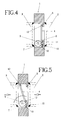
- the hinge pin 9 is aligned with the point of contact 11 between the gate 4 and the seat 5 of the valve body 1, which ensures fluidtightness of the unit and correct running of the system.
- sealing means between the gate 4 and the seat 5 of the valve can be appreciated clearly, these means preferably consisting of an O-ring of suitable material, such as neoprene.
- the hinge pin 9 is detachable. Furthermore, the ends 13,14 of said pin 9 are designed to receive protecting plugs (not shown) to prevent access to the pin.
- the hinge pin 9 is mounted inside the body 7 with a play of 0.7-0.8 mm so as to suitably set the alignment of said pin 9 with the point of contact 11.
- a portion of the seat 5 is extended to form a projection 15 whose height is designed to act as a stop of the body 7 upon opening.
Landscapes
- Engineering & Computer Science (AREA)
- General Engineering & Computer Science (AREA)
- Mechanical Engineering (AREA)
- Safety Valves (AREA)
- Lift Valve (AREA)
- Check Valves (AREA)
Applications Claiming Priority (2)
| Application Number | Priority Date | Filing Date | Title |
|---|---|---|---|
| ES9802172 | 1998-10-19 | ||
| ES009802172A ES2156507B1 (es) | 1998-10-19 | 1998-10-19 | Valvula de retencion, especialmente para circuitos neumaticos. |
Publications (2)
| Publication Number | Publication Date |
|---|---|
| EP0995934A2 true EP0995934A2 (de) | 2000-04-26 |
| EP0995934A3 EP0995934A3 (de) | 2001-10-24 |
Family
ID=8305492
Family Applications (1)
| Application Number | Title | Priority Date | Filing Date |
|---|---|---|---|
| EP99500177A Ceased EP0995934A3 (de) | 1998-10-19 | 1999-10-06 | Sicherheitsventil, insbesondere für pneumatische Kreisläufe |
Country Status (3)
| Country | Link |
|---|---|
| US (1) | US6192926B1 (de) |
| EP (1) | EP0995934A3 (de) |
| ES (1) | ES2156507B1 (de) |
Families Citing this family (6)
| Publication number | Priority date | Publication date | Assignee | Title |
|---|---|---|---|---|
| TW515475U (en) * | 2002-04-25 | 2002-12-21 | Ching-Shiang Liou | Waterproof valve for exhaust pipe |
| US7273062B1 (en) | 2005-01-11 | 2007-09-25 | Stender Jr David Flint | Shut-off valve for preventing the flow of liquid through a conduit, and related processes |
| CA2539133C (en) * | 2006-02-28 | 2013-06-04 | Gabe Coscarella | Valve flap for a plumbing valve |
| CA2722310A1 (en) * | 2010-11-16 | 2012-05-16 | Gabe Coscarella | Backwater valve with float |
| CA2830404C (en) | 2013-10-21 | 2019-01-22 | Gabe Coscarella | Low profile overbalanced backwater valve |
| US12180695B2 (en) | 2019-08-16 | 2024-12-31 | Gabe Coscarella | Backwater valve |
Family Cites Families (16)
| Publication number | Priority date | Publication date | Assignee | Title |
|---|---|---|---|---|
| US1018569A (en) * | 1911-01-26 | 1912-02-27 | Charles Kelty | Sewer-trap. |
| US2048088A (en) * | 1935-01-16 | 1936-07-21 | Wagner Henry | Backwater valve to be used on sewers, drains, and the like |
| US2637264A (en) * | 1950-01-14 | 1953-05-05 | Waterloo Foundry Company | Closure for exhaust pipe for gas engines |
| BE791878A (fr) * | 1971-11-26 | 1973-03-16 | Bryan Donkin Co Ltd | Perfectionnement aux clapets de non-retour |
| FR2271471A1 (en) * | 1974-05-14 | 1975-12-12 | Petrolieres Et | Non return-type flap valve - has clamped flap mounting ring with indicating cam mounted on shaft |
| US4266569A (en) * | 1979-04-25 | 1981-05-12 | Wilson Harold L | Check valve |
| US4304255A (en) * | 1979-05-31 | 1981-12-08 | K-F Prince Valve, Inc. | Swing check valve |
| US4353390A (en) * | 1979-12-06 | 1982-10-12 | Anchor/Darling Valve Company | Swing check valve with internally balanced disc |
| US4473526A (en) * | 1980-01-23 | 1984-09-25 | Eugen Buhler | Method of manufacturing dry-pressed molded articles |
| CA1104461A (en) * | 1980-02-01 | 1981-07-07 | Heinz K. Hetz | Modulating flow control valve assembly |
| FR2484047B1 (fr) * | 1980-06-04 | 1985-07-12 | Constantin Pierre | Clapet d'obturation |
| AT380082B (de) * | 1984-01-13 | 1986-04-10 | Hoerbiger Ventilwerke Ag | Einrichtung zum regeln der foerdermenge von rotationsverdichtern |
| US4860789A (en) * | 1987-07-27 | 1989-08-29 | Scaramucci John P | Swing check valve with hinge pin insert |
| US5031659A (en) * | 1991-01-07 | 1991-07-16 | Gonzales Henry G | Sewer line relief valve |
| US5738087A (en) * | 1995-09-21 | 1998-04-14 | King; Russell W. | Aerosol medication delivery system |
| US5921862A (en) * | 1998-01-30 | 1999-07-13 | Consol, Inc. | Air flow reversal prevention door assembly |
-
1998
- 1998-10-19 ES ES009802172A patent/ES2156507B1/es not_active Expired - Fee Related
-
1999
- 1999-10-06 EP EP99500177A patent/EP0995934A3/de not_active Ceased
- 1999-10-19 US US09/420,378 patent/US6192926B1/en not_active Expired - Fee Related
Non-Patent Citations (1)
| Title |
|---|
| None |
Also Published As
| Publication number | Publication date |
|---|---|
| ES2156507A1 (es) | 2001-06-16 |
| US6192926B1 (en) | 2001-02-27 |
| EP0995934A3 (de) | 2001-10-24 |
| ES2156507B1 (es) | 2002-02-01 |
Similar Documents
| Publication | Publication Date | Title |
|---|---|---|
| US8695637B2 (en) | Gate valve pressure equalization system | |
| EP0753693B1 (de) | Rückschlagklappe mit wasserschlagabsorber | |
| US7784483B2 (en) | Backflow preventer | |
| US6192926B1 (en) | Safety valve especially for pneumatic circuits | |
| KR101469212B1 (ko) | 유량에 따라 수압 조절이 이루어지는 감압 밸브 | |
| US3348569A (en) | Valves | |
| US10190697B2 (en) | Stuffing box lug | |
| US2441705A (en) | Plug cock valve | |
| US3076470A (en) | Vacuum breaking check and shut-off valve | |
| KR20110002357A (ko) | 안전 방출 밸브 | |
| CN100564971C (zh) | 减压装置的外壳系统 | |
| KR102753233B1 (ko) | 개폐압력조절형 글로브 밸브 | |
| CN219492739U (zh) | 一种先导式溢流阀 | |
| RU2191308C2 (ru) | Устройство для регулирования перепада давления | |
| US4809739A (en) | Check valve | |
| RU135049U1 (ru) | Клапан запорный | |
| CN117189922A (zh) | 具有弹簧结构的安全阀 | |
| CN217328537U (zh) | 一种粉料、浆料卸放专用阀 | |
| US4378932A (en) | Pressure responsive valve assembly | |
| KR101307117B1 (ko) | 스톱밸브 기능을 구비한 셀프 클로징 밸브 | |
| DE29809524U1 (de) | Deckelloser Ventileinsatz für Faltenbalgventile | |
| CN217683401U (zh) | 重力型逆止阀 | |
| CN117146022B (zh) | 一种短行程的水泵调压阀 | |
| KR200157842Y1 (ko) | 유체의 불균형 압력에 의해 자동으로 개폐되는 밸브장치 | |
| US3677279A (en) | Automatic gas-trap |
Legal Events
| Date | Code | Title | Description |
|---|---|---|---|
| PUAI | Public reference made under article 153(3) epc to a published international application that has entered the european phase |
Free format text: ORIGINAL CODE: 0009012 |
|
| AK | Designated contracting states |
Kind code of ref document: A2 Designated state(s): AT BE CH CY DE DK ES FI FR GB GR IE IT LI LU MC NL PT SE |
|
| AX | Request for extension of the european patent |
Free format text: AL;LT;LV;MK;RO;SI |
|
| PUAL | Search report despatched |
Free format text: ORIGINAL CODE: 0009013 |
|
| AK | Designated contracting states |
Kind code of ref document: A3 Designated state(s): AT BE CH CY DE DK ES FI FR GB GR IE IT LI LU MC NL PT SE |
|
| AX | Request for extension of the european patent |
Free format text: AL;LT;LV;MK;RO;SI |
|
| RIC1 | Information provided on ipc code assigned before grant |
Free format text: 7F 16K 17/02 A, 7F 16K 15/03 B, 7F 16K 17/00 B |
|
| 17P | Request for examination filed |
Effective date: 20011207 |
|
| AKX | Designation fees paid |
Free format text: AT BE CH CY DE DK ES FI FR GB GR IE IT LI LU MC NL PT SE |
|
| 17Q | First examination report despatched |
Effective date: 20030813 |
|
| STAA | Information on the status of an ep patent application or granted ep patent |
Free format text: STATUS: THE APPLICATION HAS BEEN REFUSED |
|
| 18R | Application refused |
Effective date: 20050530 |