EP0995953A2 - Warmwasser-Speicheranordnung - Google Patents
Warmwasser-Speicheranordnung Download PDFInfo
- Publication number
- EP0995953A2 EP0995953A2 EP99121125A EP99121125A EP0995953A2 EP 0995953 A2 EP0995953 A2 EP 0995953A2 EP 99121125 A EP99121125 A EP 99121125A EP 99121125 A EP99121125 A EP 99121125A EP 0995953 A2 EP0995953 A2 EP 0995953A2
- Authority
- EP
- European Patent Office
- Prior art keywords
- flow
- storage
- arrangement according
- wall
- water
- Prior art date
- Legal status (The legal status is an assumption and is not a legal conclusion. Google has not performed a legal analysis and makes no representation as to the accuracy of the status listed.)
- Withdrawn
Links
Images


Classifications
-
- F—MECHANICAL ENGINEERING; LIGHTING; HEATING; WEAPONS; BLASTING
- F28—HEAT EXCHANGE IN GENERAL
- F28D—HEAT-EXCHANGE APPARATUS, NOT PROVIDED FOR IN ANOTHER SUBCLASS, IN WHICH THE HEAT-EXCHANGE MEDIA DO NOT COME INTO DIRECT CONTACT
- F28D20/00—Heat storage plants or apparatus in general; Regenerative heat-exchange apparatus not covered by groups F28D17/00 or F28D19/00
- F28D20/0034—Heat storage plants or apparatus in general; Regenerative heat-exchange apparatus not covered by groups F28D17/00 or F28D19/00 using liquid heat storage material
- F28D20/0039—Heat storage plants or apparatus in general; Regenerative heat-exchange apparatus not covered by groups F28D17/00 or F28D19/00 using liquid heat storage material with stratification of the heat storage material
-
- F—MECHANICAL ENGINEERING; LIGHTING; HEATING; WEAPONS; BLASTING
- F28—HEAT EXCHANGE IN GENERAL
- F28D—HEAT-EXCHANGE APPARATUS, NOT PROVIDED FOR IN ANOTHER SUBCLASS, IN WHICH THE HEAT-EXCHANGE MEDIA DO NOT COME INTO DIRECT CONTACT
- F28D20/00—Heat storage plants or apparatus in general; Regenerative heat-exchange apparatus not covered by groups F28D17/00 or F28D19/00
- F28D2020/0065—Details, e.g. particular heat storage tanks, auxiliary members within tanks
- F28D2020/0069—Distributing arrangements; Fluid deflecting means
-
- F—MECHANICAL ENGINEERING; LIGHTING; HEATING; WEAPONS; BLASTING
- F28—HEAT EXCHANGE IN GENERAL
- F28D—HEAT-EXCHANGE APPARATUS, NOT PROVIDED FOR IN ANOTHER SUBCLASS, IN WHICH THE HEAT-EXCHANGE MEDIA DO NOT COME INTO DIRECT CONTACT
- F28D20/00—Heat storage plants or apparatus in general; Regenerative heat-exchange apparatus not covered by groups F28D17/00 or F28D19/00
- F28D2020/0065—Details, e.g. particular heat storage tanks, auxiliary members within tanks
- F28D2020/0082—Multiple tanks arrangements, e.g. adjacent tanks, tank in tank
-
- Y—GENERAL TAGGING OF NEW TECHNOLOGICAL DEVELOPMENTS; GENERAL TAGGING OF CROSS-SECTIONAL TECHNOLOGIES SPANNING OVER SEVERAL SECTIONS OF THE IPC; TECHNICAL SUBJECTS COVERED BY FORMER USPC CROSS-REFERENCE ART COLLECTIONS [XRACs] AND DIGESTS
- Y02—TECHNOLOGIES OR APPLICATIONS FOR MITIGATION OR ADAPTATION AGAINST CLIMATE CHANGE
- Y02B—CLIMATE CHANGE MITIGATION TECHNOLOGIES RELATED TO BUILDINGS, e.g. HOUSING, HOUSE APPLIANCES OR RELATED END-USER APPLICATIONS
- Y02B10/00—Integration of renewable energy sources in buildings
- Y02B10/20—Solar thermal
-
- Y—GENERAL TAGGING OF NEW TECHNOLOGICAL DEVELOPMENTS; GENERAL TAGGING OF CROSS-SECTIONAL TECHNOLOGIES SPANNING OVER SEVERAL SECTIONS OF THE IPC; TECHNICAL SUBJECTS COVERED BY FORMER USPC CROSS-REFERENCE ART COLLECTIONS [XRACs] AND DIGESTS
- Y02—TECHNOLOGIES OR APPLICATIONS FOR MITIGATION OR ADAPTATION AGAINST CLIMATE CHANGE
- Y02E—REDUCTION OF GREENHOUSE GAS [GHG] EMISSIONS, RELATED TO ENERGY GENERATION, TRANSMISSION OR DISTRIBUTION
- Y02E60/00—Enabling technologies; Technologies with a potential or indirect contribution to GHG emissions mitigation
- Y02E60/14—Thermal energy storage
Definitions
- the invention relates to a hot water storage arrangement according to the preamble of claim 1.
- Hot water storage arrangements according to the storage-in-storage construction principle have the advantageous property that compared to an arrangement with two separate memories, no significant increase in the size of the surroundings facing surface of heated storage areas.
- the internal storage serves as a domestic hot water storage and the main storage as a heating water tank, which in particular can also be solar-heated can.
- Such memory-in-memory arrangements are systems with heat exchangers especially preferable when high hot water tapping capacities are needed for a short time are needed.
- FIG. 3-1 describes a version in which a domestic hot water tank is arranged within a solar-heated main memory.
- the inner storage is of a small distance from its wall Surrounding the shell.
- the narrow space between the shell and the inner storage has an inflow opening at its upper edge and opens out at its lowest point in a reaching to the bottom of the main memory Outlet pipe.
- the object of the present invention is a hot water storage arrangement according to the storage-in-storage construction principle, which improves the utilization of the heating water in the main storage tank energy supplied for domestic water heating shows.
- the maintenance of low temperatures in the lower storage area enables higher efficiency when heating the heating water via condensing boilers or in particular solar collectors. Because the outflow in the outflow channel cooled heating water at the level of a heating water layer essentially the same density in the main memory, the flow is not dependent on the construction of lower cooler heating water layers.
- Another advantageous way of using energy in a storage-in-storage system to improve is in between the cladding wall and to provide internal storage formed gap or the outflow channel guide structures, which are directed towards a free flow and reduce it.
- Flow-reducing guide structures arranged in the outflow channel are preferably arranged in front of a first lateral opening. The Decreasing the flow causes longer periods of time with high ones Temperature flowing from the main memory into the flow gap Heating water in the flow gap and thus an increased heat emission the internal storage. Ideally this has to enter the outflow channel Water is essentially the same temperature as the coolest surface of the internal storage against the flow gap.
- Baffles can restrict flow cross-sections, for example be, which in particular at the transition of the flow gap to the outflow channel or arranged at the upper inlet opening of the flow channel could be.
- Other advantageous embodiments can use detour elements be in the flow gap, which is a flow on the shortest path between the upper inlet opening of the flow gap and transition to the outflow channel oppose and redirect the current.
- detour elements in a substantially vertical Section of the flow gap a horizontal flow component and in an essentially horizontal section (with respect to the outlet to the outflow channel) cause tangential flow component.
- the detour elements can also have a uniform flow around the inner memory non-uniform thickness of the flow gap due to manufacturing tolerances cause.
- the guide structures can advantageously be made of material with low thermal conductivity consist.
- the thickness of the flow gap as a distance between Inner storage and the surrounding wall is advantageously at least in the major part of the flow gap less than 10 mm, in particular less than 4 mm, which on the one hand creates a favorable ratio from the loaded surface of the internal storage to the volume of the Gap located heating water results, and on the other hand sufficient Flow of heating water is given through the flow gap.
- the individual parameters of the lead structures influencing the flow and / or the dimensioning of the flow gap can be used to adapt the Arrangement can be varied to meet different performance requirements.
- the Domestic hot water tank typically has a cylindrical cylinder that is in itself used Shape with a floor arched towards the main store, but without the invention is limited to a specific geometry of the inner memory.
- the wall of the inner accumulator facing the flow gap exists advantageously made of good heat-conducting material, typically steel, whereas the envelope wall delimiting the flow gap to the main storage shows poor thermal conductivity and, for example, made of plastic can exist.
- the wall of the inner storage can be used for better heat transfer from heating water in the flow gap to process water in the internal storage in the flow gap and / or inside the inner memory have pointing surface-enlarging structures such as ribs. Such structures can also serve as guiding structures for influencing the flow serve.
- Another advantageous measure for heating the domestic water in the internal storage of a memory-in-memory system is that inside of the inner storage a guide wall at a short distance from the inner storage wall especially over a vertical section of the inner storage wall runs and forms an inflow gap in the inner memory.
- the hot water withdrawal typically takes place via one arranged at the top in the internal memory
- the outlet and incoming cold water are fed through an inlet pipe led into the lower area of the internal memory.
- the outflow channel can advantageously be in the manner of one in DE 19704914 C1 described layer channel with a variety of lateral outlets be and extend essentially to the bottom of the main memory. That in Heating channel sinking and flowing out laterally can experience an initial reversal of the flow direction of more than 90 ° and by baffles essentially horizontally into the main storage environment be layered.
- the heating water can also be heated, in particular, using solar collectors take place, a layering of heated heating water over a Stratified loading device such as the type of the aforementioned DE 19704914 C1 is particularly advantageous and effective.
- the invention is also for heat transfer in the opposite direction can be used from an internal memory in a main memory, then the internal memory is arranged in the lower area of the main memory and with externally heated water is supplied.
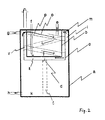
- the storage arrangement not sketched to scale in cross section in FIG. 1 shows a domestic water storage b as an internal storage within a Heating water storage a as the main storage.
- the charging of the main memory a takes place, for example, via solar collectors, for which a hot water supply is shown schematically g in the upper storage area and a cold water drain h in the lower Memory area of the main memory a are shown.
- a hot water supply is shown schematically g in the upper storage area and a cold water drain h in the lower Memory area of the main memory a are shown.
- a buffer storage with a solar system are different Embodiments known per se can also be used here. It is particularly advantageous the hot water supply via a known in various variations Stratified loading device.
- opening g serve as flow and opening h as return.
- the inner storage is surrounded on the sides and below by an envelope wall c, which has a low thermal conductivity and against the internal storage the heating water in the main storage is largely insulated thermally.
- the wall c runs at least predominantly at a small distance n from the internal memory and includes with it a flow gap i.
- the distance n is, for example in the order of 2 mm.
- the flow gap i points upward to the main storage volume m, which consists, for example, of an annular gap, of several can consist of evenly distributed partial openings etc.
- a flow of heating water evenly distributed over the circumference the main memory is advantageous.
- the envelope wall c has in its lower region, preferably at its deepest Set up an outflow opening d, which is located in the lower area k of the main store reaching outflow channel lan.
- the outflow channel has a plurality of side outlet openings w on different Height up.
- the outlet openings can, in particular, be low in turbulence Stratification ensuring form.
- the Outflow channel is preferably made of material with low thermal conductivity.
- the internal storage on the other hand, consists of a material with higher thermal conductivity, to ensure good heat transfer from the one flowing through the flow gap i To allow heating water to the domestic water.
- the cooled heating water drops in the discharge duct I to a height in which the same temperature and the surrounding heating water in the main storage thus has the same density.
- Through the majority of the side outlet openings can the cooled water sinking in the channel in the amount of Heating water layer emerge of the same density, so that hardly any turbulence and Mixing of water volumes of different temperatures take place. This is particularly the case when supplying energy via condensing systems or Solar collectors important for high energy utilization.
- the flow rate is for high energy utilization when heating the To keep domestic water as low as possible that the temperature of the Outflow opening into the outflow heating water equal to that lowest temperature of the domestic water in the internal storage tank.
- the time to reheat the domestic water after withdrawal and The cold water inlet may remain in a different frame depending on the application.
- the flow rate which in individual cases has a particularly favorable heat transfer behavior results, for example, by the thickness n of the flow gap to be influenced.
- Another advantageous measure for influencing the flow rate sees lead structures in the form of cross-sectional narrowing Flow orifices in the outflow opening d and / or the inflow opening m in front of the residence time of the heating water in the flow gap can increase.
- Guiding structures are provided which allow a free flow on the shortest Oppose the way and so the residence time of the heating water in the flow gap compared to arrangements of the same geometry without such Increase lead structures.
- lead structures in a essential vertical section v of the flow channel horizontal flow components and / or in a substantially horizontal section z of the flow channel cause tangential flow components.
- in the 2 is such a line structure with in the vertical section v of the flow channel flow-guiding elements running helically around the inner accumulator p indicated, which to an oblique flow o to lead. The way in which the heating water on the inner storage wall flows along is significantly increased.
- the guide structures can also be arranged in the outflow channel, but there then above the uppermost side outlet opening.
- the different Lead structures can also be implemented in combination and work together.
- FIG. 5A The helical guide structure p outlined in cross section in FIG. 2 is shown in FIG. 5A as Jacket processing outlined.
- FIG. 5B Another advantageous example of a flow reducing Guide structure in the vertical section v of the flow gap, with offset in vertical direction in successive levels to gap arranged deflection elements pB is also in Fig. 5B as a jacket development outlined.
- Such a lead structure has an increasingly non-linear flow reducing effect, in such a way that faster currents at larger temperature differences are braked more strongly, whereas slow currents at low Differences in temperature are only slightly obstructed.
- a lead structure with Detour elements pC for the substantially horizontal section z of the Flow channel at the area of the bottom of the internal storage is shown in FIG. 5C as Multiple meandering flow path outlined.
- FIG. 5C Multiple meandering flow path outlined.
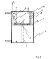
- 3 differs from the example 1 in the interior of the inner memory at a short distance, for example again about 2 mm along the side wall and preferably except for one central recess u also a guide wall along the bottom of the internal storage q arranged, which has an inflow gap with the inner storage wall r forms.
- This guide wall has the advantageous effect that that of the Heating water in the flow gap concentrates a small heat Domestic water volume is supplied in the upstream gap, which thereby quickly to a high temperature, ideally the temperature of the in the Flow gap i inflowing heating water can be heated, in particular also due to the countercurrent movement of the hot heating water in the flow gap i on the one hand and the process water in the upstream gap r.
- Heated service water flowing out at the top also forms with previously hot water completely cooled by cold water supply quickly Layer of heated service water at the discharge opening e over the otherwise cool domestic water.
- the layer boundary is increasingly down postponed, always the favorable for a high heat transfer line Condition of the inflow of cool service water into the lower inflow opening the upflow channel is given.
- the guide wall q advantageously exists from a poorly heat-conducting material, in particular from Plastic such as polypropylene.
- Also in the inflow gap r can as described for the flow gap i flow-inhibiting guide structures be provided.
- the arrangement sketched in FIG. 4 connects the detour guide structure according to FIG. 2 with the guide wall in the internal memory according to FIG. 3 and thus achieves a particular one advantageous heat transfer from the heating water to the domestic water.
- the invention is not restricted to the exemplary embodiments described, Can be modified in many ways within the scope of professional skills.
- the designs of main storage and internal storage are giving way typically depending on the simple outline.
Landscapes
- Engineering & Computer Science (AREA)
- Physics & Mathematics (AREA)
- Thermal Sciences (AREA)
- Mechanical Engineering (AREA)
- General Engineering & Computer Science (AREA)
- Heat-Pump Type And Storage Water Heaters (AREA)
Abstract
Description
- Fig. 1
- einen Querschnitt durch eine erste Ausführungsform
- Fig. 2
- eine Ausführungsform mit Leitstrukturen
- Fig. 3
- eine Ausführungsform mit Strömungsführungen im Innenspeicher
- Fig. 4
- eine Kombination der Ausführungen nach Fig. 2 und 3
- Fig. 5
- Beispiele für Leitstrukturen
Claims (10)
- Warmwasser-Speicheranordnung mit einem Hauptspeicher und einem in dessen oberem Bereich angeordneten Innenspeicher, wobei der Innenspeicher von einer gering beabstandeten Hüllwand umgeben ist, welche mit dem Innenspeicher einen oben zum Hauptspeicher offenen Strömungsspalt bildet und nach unten in einen in den unteren Bereich des Hauptspeichers führenden Abströmkanal mündet, dadurch gekennzeichnet, daß der Abströmkanal eine Mehrzahl seitlicher Öffnungen auf unterschiedlicher Höhe aufweist.
- Anordnung nach Anspruch 1, dadurch gekennzeichnet, daß in dem Strömungsspalt und/oder dem Abströmkanal Leitstrukturen ausgebildet sind, welche der freien Strömung entgegenwirken.
- Anordnung nach Anspruch 2, dadurch gekennzeichnet, daß der Strömungsspalt in einem vertikalen Abschnitt Leitstrukturen zur Erzeugung horizontaler Strömungskomponenten aufweist.
- Anordnung nach Anspruch 2 oder 3, dadurch gekennzeichnet, daß der Strömungsspalt in einem sich radial vor dem Abströmkanal verbreiternden flachen oder kegeligen Abschnitt Leitstrukturen zur Erzeugung tangentialer Strömungskomponenten aufweist.
- Anordnung nach einem der Ansprüche 1 bis 4, dadurch gekennzeichnet, daß eine innerhalb des Innenspeichers angeordnete Leitwandung in geringem Abstand von dessen seitlicher Innenwand verläuft und mit dieser einen Aufströmspalt mit einer tiefliegenden Einströmöffnung und einer hochliegenden Ausströmöffnung bildet.
- Anordnung nach einem der Ansprüche 1 bis 5, dadurch gekennzeichnet, daß die seitlichen Öffnungen des Abströmkanals als Strömungsführungen mit einer Umlenkung der Strömungsrichtung gegen die Hauptströmungsrichtung im Abströmkanal von mehr als 90 ° ausgebildet sind.
- Anordnung nach einem der Ansprüche 1 bis 6, dadurch gekennzeichnet, daß die Wand des Innenspeichers aus gut wärmeleitendem Material besteht.
- Anordnung nach einem der Ansprüche 1 bis 7, dadurch gekennzeichnet, daß die Hüllwand und der Abströmkanal ein geringes Wärmeleitvermögen aufweisen.
- Anordnung nach einem der Ansprüche 1 bis 8, dadurch gekennzeichnet, daß die Wand des Innenspeichers mit nach innen und/oder mit nach außen weisenden oberflächenvergrößernden Strukturen, beispielsweise Rippen, versehen ist.
- Anordnung nach einem der Ansprüche 1 bis 9, dadurch gekennzeichnet, daß der Abstand zwischen Hüllwand und Innenspeicher zumindest im überwiegenden Verlauf des Strömungskanals kleiner als 10 mm, insbesondere kleiner als 4 mm ist.
Applications Claiming Priority (2)
| Application Number | Priority Date | Filing Date | Title |
|---|---|---|---|
| DE1998148648 DE19848648C2 (de) | 1998-10-22 | 1998-10-22 | Warmwasserschichtspeicher |
| DE19848648 | 1998-10-22 |
Publications (2)
| Publication Number | Publication Date |
|---|---|
| EP0995953A2 true EP0995953A2 (de) | 2000-04-26 |
| EP0995953A3 EP0995953A3 (de) | 2001-07-18 |
Family
ID=7885250
Family Applications (1)
| Application Number | Title | Priority Date | Filing Date |
|---|---|---|---|
| EP99121125A Withdrawn EP0995953A3 (de) | 1998-10-22 | 1999-10-22 | Warmwasser-Speicheranordnung |
Country Status (2)
| Country | Link |
|---|---|
| EP (1) | EP0995953A3 (de) |
| DE (1) | DE19848648C2 (de) |
Cited By (1)
| Publication number | Priority date | Publication date | Assignee | Title |
|---|---|---|---|---|
| WO2017032389A1 (de) * | 2015-08-27 | 2017-03-02 | Krisolplast Gmbh | Vorrichtung zum einspeisen eines fluids und deren verwendung |
Families Citing this family (1)
| Publication number | Priority date | Publication date | Assignee | Title |
|---|---|---|---|---|
| AT511289B1 (de) | 2011-02-18 | 2013-01-15 | Laabmayr Robert | Wärmespeicher |
Family Cites Families (3)
| Publication number | Priority date | Publication date | Assignee | Title |
|---|---|---|---|---|
| DE2712733A1 (de) * | 1977-03-23 | 1978-09-28 | Froeling Kessel App | Mehrkreis-heizungsanlage |
| DE4411352C1 (de) * | 1994-03-31 | 1995-05-04 | Solar Diamant Syst | Warmwasserspeicher |
| DE19710803C2 (de) * | 1997-03-17 | 1999-09-02 | Wagner & Co Solartechnik Gmbh | Warmwasser-Speichersystem |
-
1998
- 1998-10-22 DE DE1998148648 patent/DE19848648C2/de not_active Expired - Fee Related
-
1999
- 1999-10-22 EP EP99121125A patent/EP0995953A3/de not_active Withdrawn
Cited By (2)
| Publication number | Priority date | Publication date | Assignee | Title |
|---|---|---|---|---|
| WO2017032389A1 (de) * | 2015-08-27 | 2017-03-02 | Krisolplast Gmbh | Vorrichtung zum einspeisen eines fluids und deren verwendung |
| EP3163207A1 (de) | 2015-08-27 | 2017-05-03 | Ralph Kettl | Vorrichtung zum einspeisen eines fluids und deren verwendung |
Also Published As
| Publication number | Publication date |
|---|---|
| DE19848648C2 (de) | 2002-11-07 |
| DE19848648C1 (de) | 1999-12-09 |
| EP0995953A3 (de) | 2001-07-18 |
Similar Documents
| Publication | Publication Date | Title |
|---|---|---|
| DE60022572T2 (de) | Verdampfer | |
| DE2925272A1 (de) | Waermetauscher | |
| AT215562B (de) | Hülle für Brennstoffelemente von Kernreaktoren | |
| EP0200809A2 (de) | Ölfilter mit integriertem Wärmetauscher | |
| DE19731351A1 (de) | Speicherwassererwärmer | |
| DE202023103949U1 (de) | Eine Kombinationsvorrichtung zur Wärmebehandlung, Abschreckung und Kühlung von Stahlkugeln für die thermische Energieerzeugung | |
| DE3044079C2 (de) | Warmwasserspeicher | |
| EP0995953A2 (de) | Warmwasser-Speicheranordnung | |
| EP0861985A2 (de) | Vorrichtung zur vertikalen Temperaturschichtung eines Fluids in einem Speicherbehälter | |
| EP1634022B1 (de) | Vorrichtung zum erwärmen eines im kreislauf einer wärme pumpe geführten kältemittels | |
| EP1158259A2 (de) | Schichtspeicher | |
| AT511289A1 (de) | Wärmespeicher | |
| DE1909214A1 (de) | Vorrichtung zur fraktionierten Destillation einer Fluessigkeit,insbesondere von Meerwasser | |
| DE20317011U1 (de) | Warmwasserspeicher mit doppelwandigem kanalförmigem Gegenstromwärmetauscher | |
| DE2715268C3 (de) | Wärmeaustauscheinrichtung für eine wärmegebende Primärflüssigkeit und zwei voneinander getrennte wärmeaufnehmende Sekundärmedien | |
| DE3119855A1 (de) | Waermetauscher zur rueckgewinnung von abwaerme | |
| DE2816293A1 (de) | Kuehlturm | |
| DE2901304A1 (de) | Sonnenenergiekollektor | |
| DE19516837A1 (de) | Behälter mit einer Flüssigkeit zur Wärme- oder Kältespeicherung | |
| DE1404208A1 (de) | Heizwasserspeicherbehaelter | |
| DE3113354C2 (de) | ||
| DE29816006U1 (de) | Haus- oder Raumheizungssystem mit Wärmespeicherung | |
| DE29820047U1 (de) | Pufferspeicher | |
| DE102018221410A1 (de) | Heizeinrichtung für Wasser | |
| DE29813784U1 (de) | Warmwasserspeicher |
Legal Events
| Date | Code | Title | Description |
|---|---|---|---|
| PUAI | Public reference made under article 153(3) epc to a published international application that has entered the european phase |
Free format text: ORIGINAL CODE: 0009012 |
|
| AK | Designated contracting states |
Kind code of ref document: A2 Designated state(s): AT BE CH CY DE DK ES FI FR GB GR IE IT LI LU MC NL PT SE |
|
| AX | Request for extension of the european patent |
Free format text: AL;LT;LV;MK;RO;SI |
|
| PUAL | Search report despatched |
Free format text: ORIGINAL CODE: 0009013 |
|
| AK | Designated contracting states |
Kind code of ref document: A3 Designated state(s): AT BE CH CY DE DK ES FI FR GB GR IE IT LI LU MC NL PT SE |
|
| AX | Request for extension of the european patent |
Free format text: AL;LT;LV;MK;RO;SI |
|
| 17P | Request for examination filed |
Effective date: 20020118 |
|
| AKX | Designation fees paid |
Free format text: DE |
|
| RBV | Designated contracting states (corrected) |
Designated state(s): AT BE CH CY DE DK ES FI FR GB GR IE IT LI LU MC NL PT SE |
|
| STAA | Information on the status of an ep patent application or granted ep patent |
Free format text: STATUS: THE APPLICATION IS DEEMED TO BE WITHDRAWN |
|
| 18D | Application deemed to be withdrawn |
Effective date: 20050403 |