EP0995972A1 - Mecanisme de modification de l'angle de fixation d'un capteur gyroscopique integre et procede de montage de ce mecanisme de modification de l'angle de fixation - Google Patents
Mecanisme de modification de l'angle de fixation d'un capteur gyroscopique integre et procede de montage de ce mecanisme de modification de l'angle de fixation Download PDFInfo
- Publication number
- EP0995972A1 EP0995972A1 EP97930755A EP97930755A EP0995972A1 EP 0995972 A1 EP0995972 A1 EP 0995972A1 EP 97930755 A EP97930755 A EP 97930755A EP 97930755 A EP97930755 A EP 97930755A EP 0995972 A1 EP0995972 A1 EP 0995972A1
- Authority
- EP
- European Patent Office
- Prior art keywords
- housed
- gyro
- sensor
- navigation system
- car navigation
- Prior art date
- Legal status (The legal status is an assumption and is not a legal conclusion. Google has not performed a legal analysis and makes no representation as to the accuracy of the status listed.)
- Withdrawn
Links
Images


Classifications
-
- G—PHYSICS
- G01—MEASURING; TESTING
- G01C—MEASURING DISTANCES, LEVELS OR BEARINGS; SURVEYING; NAVIGATION; GYROSCOPIC INSTRUMENTS; PHOTOGRAMMETRY OR VIDEOGRAMMETRY
- G01C21/00—Navigation; Navigational instruments not provided for in groups G01C1/00 - G01C19/00
- G01C21/26—Navigation; Navigational instruments not provided for in groups G01C1/00 - G01C19/00 specially adapted for navigation in a road network
-
- G—PHYSICS
- G01—MEASURING; TESTING
- G01C—MEASURING DISTANCES, LEVELS OR BEARINGS; SURVEYING; NAVIGATION; GYROSCOPIC INSTRUMENTS; PHOTOGRAMMETRY OR VIDEOGRAMMETRY
- G01C19/00—Gyroscopes; Turn-sensitive devices using vibrating masses; Turn-sensitive devices without moving masses; Measuring angular rate using gyroscopic effects
-
- G—PHYSICS
- G01—MEASURING; TESTING
- G01C—MEASURING DISTANCES, LEVELS OR BEARINGS; SURVEYING; NAVIGATION; GYROSCOPIC INSTRUMENTS; PHOTOGRAMMETRY OR VIDEOGRAMMETRY
- G01C21/00—Navigation; Navigational instruments not provided for in groups G01C1/00 - G01C19/00
- G01C21/10—Navigation; Navigational instruments not provided for in groups G01C1/00 - G01C19/00 by using measurements of speed or acceleration
- G01C21/12—Navigation; Navigational instruments not provided for in groups G01C1/00 - G01C19/00 by using measurements of speed or acceleration executed aboard the object being navigated; Dead reckoning
- G01C21/16—Navigation; Navigational instruments not provided for in groups G01C1/00 - G01C19/00 by using measurements of speed or acceleration executed aboard the object being navigated; Dead reckoning by integrating acceleration or speed, i.e. inertial navigation
- G01C21/166—Mechanical, construction or arrangement details of inertial navigation systems
-
- Y—GENERAL TAGGING OF NEW TECHNOLOGICAL DEVELOPMENTS; GENERAL TAGGING OF CROSS-SECTIONAL TECHNOLOGIES SPANNING OVER SEVERAL SECTIONS OF THE IPC; TECHNICAL SUBJECTS COVERED BY FORMER USPC CROSS-REFERENCE ART COLLECTIONS [XRACs] AND DIGESTS
- Y10—TECHNICAL SUBJECTS COVERED BY FORMER USPC
- Y10T—TECHNICAL SUBJECTS COVERED BY FORMER US CLASSIFICATION
- Y10T74/00—Machine element or mechanism
- Y10T74/12—Gyroscopes
- Y10T74/1218—Combined
-
- Y—GENERAL TAGGING OF NEW TECHNOLOGICAL DEVELOPMENTS; GENERAL TAGGING OF CROSS-SECTIONAL TECHNOLOGIES SPANNING OVER SEVERAL SECTIONS OF THE IPC; TECHNICAL SUBJECTS COVERED BY FORMER USPC CROSS-REFERENCE ART COLLECTIONS [XRACs] AND DIGESTS
- Y10—TECHNICAL SUBJECTS COVERED BY FORMER USPC
- Y10T—TECHNICAL SUBJECTS COVERED BY FORMER US CLASSIFICATION
- Y10T74/00—Machine element or mechanism
- Y10T74/12—Gyroscopes
- Y10T74/1229—Gyroscope control
- Y10T74/1232—Erecting
-
- Y—GENERAL TAGGING OF NEW TECHNOLOGICAL DEVELOPMENTS; GENERAL TAGGING OF CROSS-SECTIONAL TECHNOLOGIES SPANNING OVER SEVERAL SECTIONS OF THE IPC; TECHNICAL SUBJECTS COVERED BY FORMER USPC CROSS-REFERENCE ART COLLECTIONS [XRACs] AND DIGESTS
- Y10—TECHNICAL SUBJECTS COVERED BY FORMER USPC
- Y10T—TECHNICAL SUBJECTS COVERED BY FORMER US CLASSIFICATION
- Y10T74/00—Machine element or mechanism
- Y10T74/12—Gyroscopes
- Y10T74/1229—Gyroscope control
- Y10T74/1232—Erecting
- Y10T74/1243—Erecting by weight
-
- Y—GENERAL TAGGING OF NEW TECHNOLOGICAL DEVELOPMENTS; GENERAL TAGGING OF CROSS-SECTIONAL TECHNOLOGIES SPANNING OVER SEVERAL SECTIONS OF THE IPC; TECHNICAL SUBJECTS COVERED BY FORMER USPC CROSS-REFERENCE ART COLLECTIONS [XRACs] AND DIGESTS
- Y10—TECHNICAL SUBJECTS COVERED BY FORMER USPC
- Y10T—TECHNICAL SUBJECTS COVERED BY FORMER US CLASSIFICATION
- Y10T74/00—Machine element or mechanism
- Y10T74/12—Gyroscopes
- Y10T74/1229—Gyroscope control
- Y10T74/1257—Damping
-
- Y—GENERAL TAGGING OF NEW TECHNOLOGICAL DEVELOPMENTS; GENERAL TAGGING OF CROSS-SECTIONAL TECHNOLOGIES SPANNING OVER SEVERAL SECTIONS OF THE IPC; TECHNICAL SUBJECTS COVERED BY FORMER USPC CROSS-REFERENCE ART COLLECTIONS [XRACs] AND DIGESTS
- Y10—TECHNICAL SUBJECTS COVERED BY FORMER USPC
- Y10T—TECHNICAL SUBJECTS COVERED BY FORMER US CLASSIFICATION
- Y10T74/00—Machine element or mechanism
- Y10T74/12—Gyroscopes
- Y10T74/1289—Horizontal gyroscopes
Definitions
- the present invention relates to a method of mounting a variable mechanism for a mounting angle and to a housed gyro-sensor unit which can make a mounting angle of a housed gyro-sensor unit horizontal without reference to a mounting angle of a navigation system in a vehicle.
- Figure 1 is a schematic view of a car navigation system which has a housed gyro-sensor.
- Figure 2 is a view of the state of a housed gyro-sensor when the car navigation system is mounted in an inclined position.
- reference numeral 1 denotes car navigation system housed in a dashboard
- 2 is a housed gyro-sensor fixed to the car navigation system.
- the housed gyro-sensor 2 is preferably maintained in a horizontal position with respect to the body of the vehicle. In particular, this has been necessary with respect to a gyro-sensor detecting the variable amount or absolute value of the angle of the horizontal periphery (rate).
- the housed gyro-sensor unit device 2 Since the housed gyro-sensor unit device 2 is fixed to the car navigation system 1, it has been necessary to choose a position at which it is possible to place a car navigation system 1 horizontally when mounting the car navigation system 1 in the vehicle body in order to hold the housed gyro-sensor in a horizontal position with respect to the vehicle body.
- the present invention proposed to solve the above problems and has the object of providing of a variable mechanism for a mounting angle of a housed gyro-sensor and a method of mounting said mechanism.
- the variable mechanism of the present invention can regulate the mounting angle of the housed gyro-sensor 2 without reference to a mounting angle of a car navigation system when mounted in a vehicle body and thus can be used in an ideal state.
- the present invention has the further object of providing a method of mounting a variable mechanism for the mounting angle of a housed gyro-sensor in which horizontal adjustments are simplified.
- the present invention has the further object of providing a variable mechanism for the mounting angle of a housed gyro-sensor and a method of mounting said mechanism in which it is not necessary to regulate the horizontal position manually.
- the present invention has the further object of providing a variable mechanism for the mounting angle of a housed gyro-sensor and a method of mounting said mechanism in which an acceleration or deceleration G generated when the vehicle is running can be prevented from affecting the variable mechanism of the housed gyro-sensor.
- variable mechanism of the housed gyro-sensor according to Claim 1 of the present invention is housed in a car navigation system and supports a housed gyro-sensor horizontally with respect to the vehicle body.
- the housed gyro-sensor detects an amount of variation or an absolute value of an angle of the horizontal periphery in the vehicle body.
- variable mechanism of the housed gyro-sensor according to Claim 2 of the present invention is supported to move with respect to the housing of a car navigation system main body and fixes a housed gyro-sensor at an arbitrary position or a fixed position depending on the mounting angle of the car navigation main body.
- variable mechanism of the housed gyro-sensor according to Claim 3 of the present invention forms a mounting hole in the housing of the car navigation system and supports a rotation plate, which houses the housed gyro-sensor, to rotate freely with respect to a pitch axis of the mounting hole.
- variable mechanism of the housed gyro-sensor forms mounting hole in the housing of the car navigation system main body and a guiding groove along the circular periphery of the mounting hole.
- a hole for a connecting pin is formed at a position, corresponding to the guiding groove, on the rotation plate which houses the housed gyro-sensor.
- the variable mechanism is supported to rotate freely with respect to the direction of pitch of the mounting hole and is fixed by a connection pin which pierces both the connection pinhole and the guiding groove.
- the variable mechanism of the housed gyro-sensor according to Claim 5 of the present invention forms a mounting hole in the housing of the car navigation system main body and a plurality of notches in the circular section.
- the rotation plate which houses the housed gyro-sensor is supported to rotate freely with respect to a pitch axis of the mounting hole and is slidably supported on the housing of the car navigation main body.
- a rotation plate stopper engages with a notch due to the pressing force of a spring member and prevents the rotation of the rotation plate.
- the variable mechanism of the housed gyro-sensor according to Claim 6 of the present invention supports a rotation plate, which houses the housed gyro-sensor, free to rotate with respect to the pitch axial direction of the mounting hole formed in the housing of the car navigation system main body.
- the rotation plate stopper which is slidably supported in the housing of the car navigation system main body is adapted to abut with the circular section of the rotation plate by spring member which presses in the direction of the rotation plate thus preventing the rotation of the rotation plate.
- variable mechanism of the housed gyro-sensor according to Claim 7 of the present invention is supported to move freely with respect to the housing of a car navigation main body and horizontally supports a housed gyro-sensor with respect to a vehicle body without reference to the angle of mounting of a car navigation system main body.
- variable mechanism of the housed gyro-sensor according to Claim 8 of the present invention engages a spherical section which is provided on the end of an arm which extends from the housed gyro-sensor with a retaining indentation in the housing of the car navigation system main body.
- variable mechanism of the housed gyro-sensor according to Claim 9 of the present invention supports a rotation plate disposing a balancer below the housed gyro-sensor to rotate freely with respect to a direction of a pitch axis of the mounting hole formed on the housing of the car navigation system main body.
- variable mechanism of the housed gyro-sensor according to Claim 10 of the present invention supports a damper having contacting ends which connect with the rotation plate in the housing of the car navigation system main body. Although a rapid rotation force of the rotation plate is absorbed, a slight rotation force of the rotation plate is not absorbed.
- the variable mechanism of the housed gyro-sensor according to Claim 11 of the present invention is provided with an inclination detection mechanism on the housing of the car navigation system main body.
- the inclination detection mechanism detects an inclination of the housed gyro-sensor and corrects an output value from the housed gyro-sensor depending on the inclination of the car navigation system main body to a value when the housed gyro-sensor is disposed horizontally.
- the method of mounting the housed gyro-sensor according to Claim 12 of the present invention entails the steps of housing the mechanism in the car navigation system and supporting the housed gyro-sensor which detects the amount of variation or the absolute value of the angle of the horizontal periphery in the vehicle body horizontally with respect to the vehicle body.
- the method of mounting the housed gyro-sensor according to Claim 13 of the present invention entails the steps of supporting the mechanism to move freely in the housing of the car navigation system and fixing the housed gyro-sensor at a fixed position or an arbitrary position depending on the angle of the mounting of the car navigation system main body.
- the method of mounting the housed gyro-sensor according to Claim 14 of the present invention entails the steps of supporting the mechanism to move freely with respect to the housing of the car navigation system and supporting the housed gyro-sensor horizontally with respect to the vehicle without reference to the mounting angle of the car navigation system main body
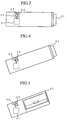
- Figure 3 is a lateral view of the car navigation system housing a variable mechanism for the mounting angle of the housed gyro-sensor according to the first embodiment of the present invention.
- Figure 4 is a lateral view of the housed gyro-sensor when the car navigation system which houses a variable mechanism for the angle of mounting a housed gyro-sensor is housed in an inclined state in a first embodiment of the present invention.
- Figure 5 is a front view of the housed gyro-sensor when the car navigation system which houses a variable mechanism for the angle of mounting a housed gyro-sensor is housed in an inclined state in a first embodiment of the present invention.
- reference numeral 21 denotes a car navigation system
- 22 is a displaceable mechanism (variable mechanism for mounting angle) comprised of a retaining indentation 23 which is fixed to the car navigation system 11 and a spherical section 32 of the housed gyro-sensor
- 23 is a retaining indentation which holds the spherical section 32 of the housed gyro-sensor 31 so as to move freely.
- 31 is a housed gyro-sensor on the upper section of which a spherical section 32 is formed through the arm and which detects a rate bearing.
- the housed gyro-sensor 31 of the first embodiment of the present invention is held to be freely movable by the retaining indentation 23 of the variable mechanism 22 through the spherical section 32. In this way, as shown in Figure 4 and Figure 5, even when the main body of the car navigation system 21 is not housed horizontally with respect to the vehicle body, it is possible to hold the housed gyro-sensor 31 horizontally with respect to the vehicle body.
- the angle of holding the housed gyro-sensor 31 does not depend on the mounting angle of the car navigation system 21 and can be maintained horizontally with respect to the vehicle body. Thus it is possible to maintain a fixed accuracy of the stored gyro-sensor 31.
- Figure 6 is an perspective view showing a car navigation system which houses a variable mechanism for the angle of mounting a housed gyro-sensor in a second embodiment of the present invention.
- Figure 7 is a lateral view of the car navigation system which houses a variable mechanism for the angle of mounting a housed gyro-sensor in a second embodiment of the present invention.
- Figure 8 is a lateral view of the housed gyro-sensor when the car navigation system which houses a variable mechanism for the angle of mounting a housed gyro-sensor is housed in an inclined state in a second embodiment of the present invention.
- those elements which are the same or similar to those in Embodiment 1 are designated by the same numerals and will not be explained further.
- Reference numeral 24 is a mounting hole (the variable mechanism for mounting angle) which is formed on the housing on the side face of the car navigation system 21.
- 33 is a rotation plate (the variable mechanism for mounting angle) which is held free to rotate with respect to the pitch axial direction of the mounting hole 24.
- the housed gyro-sensor 31 is housed on an inner side of the rotation plate 33.
- the housed gyro-sensor 31 is mounted so that it is housed inside the rotation plate 33 and can rotate in the direction of the pitch axis about an axis of the mounting hole 24 formed on the housing on the inner face of the car navigation system 21.
- the main body of the car navigation system 21 is housed in a state which is not horizontal to the vehicle, it is possible to regulate horizontally the mounting angle of the housed gyro-sensor 31 with respect to the vehicle.
- standards for angle settings may be provided by directly printing the name of the vehicle type on an outer face of the rotation plate 33 or by printing the major angles.
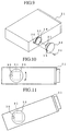
- Figure 9 is an inclined view showing a car navigation system which houses a variable mechanism for the angle of mounting a housed gyro-sensor in a third embodiment of the present invention.
- Figure 10 is a lateral view showing a car navigation system which houses a variable mechanism for the angle of mounting a housed gyro-sensor in a third embodiment of the present invention.
- Figure 11 is a lateral view of the housed gyro-sensor when the car navigation system which houses a variable mechanism for the angle of mounting a housed gyro-sensor is housed in an inclined state in a third embodiment of the present invention.
- 25 is a guiding groove (variable mechanism for mounting angle) which is formed along the periphery of the mounting hole 24.
- 34 is a connecting pinhole (variable mechanism for mounting angle) which is formed on the rotation plate 33.
- 35 is a connecting pin (variable mechanism for mounting angle) which passes through the guiding groove 25 and the connecting pinhole 34 and which guides the rotation plate 33 through a fixed angle along the guiding groove 25,
- 36 is a nut which retains the connecting pin 35 on the car navigation system 21.
- the housed gyro-sensor 31 is housed on an inner side the rotation plate 33 and is inserted into the mounting hole 24 formed on the housing on the inner face of the car navigation system 21.
- the rotation plate 33 is rotated depending on the angle of inclination of the car navigation system and held so that the horizontal axis of the housed gyro-sensor 31 is horizontal to the vehicle.
- the connecting pin 35 is inserted into the connecting pinhole 34 of the rotation plate 33 and is fixed to the housing on the inner face of the car navigation system 21 by a nut 36.
- Embodiment 3 it is possible to perform the horizontal regulation of the housed gyro-sensor 31 with a relatively simple mechanism and it is possible to prevent errors in the position of the horizontal axis of the rotation plate 33 due to vibrations from the vehicle body.
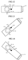
- Figure 12 is a view showing a car navigation system which houses a variable mechanism for the angle of mounting a housed gyro-sensor in a fourth embodiment of the present invention.
- Figure 13 is a lateral view of the housed gyro-sensor when the car navigation system which houses a variable mechanism for the angle of mounting a housed gyro-sensor is housed in an inclined state with the right side raised in a fourth embodiment of the present invention.
- Figure 14 is a lateral view of the housed gyro-sensor when the car navigation system which houses a variable mechanism for the angle of mounting a housed gyro-sensor is housed in an inclined state with the right side depressed in a fourth embodiment of the present invention.
- 41 is a rotation plate (variable mechanism for mounting angle) which forms a plurality of notches 41a.
- 42 is a rotation plate stopper (variable mechanism for mounting angle) which is mounted on the housing on an inner face of the car navigation system 21, the end of which is inserted into the notch 41a of the rotation plate 41 and which holds the rotation plate 41 at a fixed angle.
- 43 is a spring member (variable mechanism for mounting angle) which presses the rotation plate stopper 42 on the side of the rotation plate 41.
- a housed gyro-sensor is housed inside a rotation plate 41 and is inserted into the mounting hole 24 formed on the housing of the inner face of the car navigation system 21.
- the rotation plate 41 is rotated depending on an angle of inclination of the car navigation system and the horizontal axis of the housed gyro-sensor 31 is maintained in a horizontal position.
- the end of the rotation plate stopper 42 is inserted into the notch 41a of the rotation plate 41 and the rotation plate 41 is maintained at a fixed angle.
- the rotation plate 41 is fixed to the housing of the inner face of the car navigation system 21.
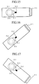
- Figure 15 is a view showing a car navigation system which houses a variable mechanism for the angle of mounting a housed gyro-sensor in a fourth embodiment of the present invention.
- Figure 16 is a lateral view of the housed gyro-sensor when the car navigation system which houses a variable mechanism for the angle of mounting a housed gyro-sensor is housed in an inclined state with the right side raised in a fifth embodiment of the present invention.
- Figure 17 is a lateral view of the housed gyro-sensor when the car navigation system which houses a variable mechanism for the angle of mounting a housed gyro-sensor is housed in an inclined state with the right side depressed in a fourth embodiment of the present invention.
- a resisting section (variable mechanism for mounting angle) which is normally in abutment with the circular section of the rotation plate 33 and which stops the rotation plate at a fixed position by the pressure from the spring member 52 (variable mechanism for mounting angle).
- the rotation plate 33 can be fixed to an arbitrary position by the force of friction between the circular section of the rotation plate 33 and the resisting section 51.
- a housed gyro-sensor 31 is housed inside a rotation plate 33 and is inserted into the mounting hole 24 formed on the housing of the inner face of the car navigation system 21.
- the rotation plate 41 is rotated depending on an angle of inclination of the car navigation system and the horizontal axis of the housed gyro-sensor 31 is maintained in a horizontal position. Thereafter the rotation force is increased to overcome the frictional force between the circular section of the rotation plate 33 and the resisting section 51.
- the rotation plate 33 can be maintained in an arbitrary position.
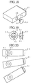
- Figure 18 is a perspective view showing a car navigation system which houses a variable mechanism for the angle of mounting a housed gyro-sensor in a sixth embodiment of the present invention.
- Figure 19 is a lateral and rear view of a variable mechanism for the angle of mounting a housed gyro-sensor in a sixth embodiment of the present invention.
- Figure 20 is a lateral view of the housed gyro-sensor when the car navigation system which houses a variable mechanism for the angle of mounting a housed gyro-sensor is housed in an inclined state with the right side depressed in a sixth embodiment of the present invention.
- 61 is a balancer (variable mechanism for mounting angle) which is housed on an end of the rear face of the rotation plate 33 which is held free to rotate in the mounting hole 24.
- the rotation plate 33 is rotated by the weight of the balancer 61 and the housed gyro-sensor 31 is maintained in a normally horizontal orientation with respect to the vehicle body.
- a housed gyro-sensor 31 is housed inside a rotation plate 41 and is inserted into the mounting hole 24 formed on the housing of the inner face of the car navigation system 21.
- the rotation plate 41 is rotated depending on an angle of inclination of the car navigation system and the horizontal axis of the housed gyro-sensor 31 is automatically maintained in a horizontal position by the balancer 61 provided on the lower face of the housed gyro-sensor 31.
- the housed gyro-sensor 31 it is not necessary to adjust the variable mechanism for the mounting angle of the housed gyro-sensor 31 manually. Furthermore the housed gyro-sensor can maintain the same level of accuracy as when normally mounted horizontally.
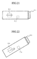
- Figure 21 is a view showing a car navigation system which houses a variable mechanism for the angle of mounting a housed gyro-sensor in a seventh embodiment of the present invention.
- Figure 22 is a lateral view of the housed gyro-sensor when the car navigation system which houses a variable mechanism for the angle of mounting a housed gyro-sensor is housed in an inclined state with the right side raised in a seventh embodiment of the present invention.
- those elements which are the same or similar to those in Embodiment 1 to Embodiment 6 are designated by the same numerals and will not be explained further.
- 71 is an inclination detection mechanism which detects an inclination ⁇ of the housed gyro-sensor 31 which is housed in the housing of the car navigation system 21 and which corrects the output value from the housed gyro-sensor 31 depending on the inclination ⁇ of the car navigation system 21.
- the inclination detection mechanism 71 which is housed in proximity to the housed gyro-sensor 31 detects an inclination ⁇ of the of the main body of the car navigation system 21.
- the output value from the housed gyro-sensor 31 depending on the inclination ⁇ of the car navigation system 21 is corrected to the value when the housed gyro-sensor 31 is disposed horizontally.
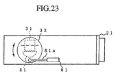
- Figure 23 is a view showing a car navigation system which houses a variable mechanism for the angle of mounting a housed gyro-sensor in an eighth embodiment of the present invention.
- 81 is a damper which has the following characteristics. The contact end 81a contacts the rotation plate 33. A rapid rotation force of the rotation plate is absorbed and a slight rotation force of the rotation plate is not absorbed.
- the rotation plate 33 When the car navigation system 1 is mounted on an incline in the vehicle body, the rotation plate 33 is rotated at a relatively low speed by the weight of the balancer 61. Thus in this case, the rotation force is not absorbed by the damper 81. Thus the rotation plate 33 rotates and the housed gyro-sensor 31 can be regulated automatically to a horizontal position.
- gravity G which is generated by the acceleration or braking of the vehicle acts on the balancer 61 and tries to rotate the rotation plate 33.
- the rotation force of the rotation plate 33 at this time is at a relatively high speed.
- the rotation force is absorbed by the damper 81. Therefore the rotation plate undergoes almost no rotation and the housed gyro-sensor is maintained in a horizontal position.
- variable mechanism for the mounting angle of a housed gyro-sensor according to the present invention and a method therefor is adapted from use with a mounting mechanism of a housed gyro-sensor in a car navigation system.
Landscapes
- Engineering & Computer Science (AREA)
- Radar, Positioning & Navigation (AREA)
- Remote Sensing (AREA)
- Physics & Mathematics (AREA)
- General Physics & Mathematics (AREA)
- Automation & Control Theory (AREA)
- Navigation (AREA)
- Gyroscopes (AREA)
Applications Claiming Priority (1)
| Application Number | Priority Date | Filing Date | Title |
|---|---|---|---|
| PCT/JP1997/002400 WO1999002943A1 (fr) | 1997-07-10 | 1997-07-10 | Mecanisme de modification de l'angle de fixation d'un capteur gyroscopique integre et procede de montage de ce mecanisme de modification de l'angle de fixation |
Publications (2)
| Publication Number | Publication Date |
|---|---|
| EP0995972A1 true EP0995972A1 (fr) | 2000-04-26 |
| EP0995972A4 EP0995972A4 (fr) | 2003-03-26 |
Family
ID=14180829
Family Applications (1)
| Application Number | Title | Priority Date | Filing Date |
|---|---|---|---|
| EP97930755A Withdrawn EP0995972A4 (fr) | 1997-07-10 | 1997-07-10 | Mecanisme de modification de l'angle de fixation d'un capteur gyroscopique integre et procede de montage de ce mecanisme de modification de l'angle de fixation |
Country Status (4)
| Country | Link |
|---|---|
| US (1) | US6301982B1 (fr) |
| EP (1) | EP0995972A4 (fr) |
| JP (1) | JP3621115B2 (fr) |
| WO (1) | WO1999002943A1 (fr) |
Cited By (8)
| Publication number | Priority date | Publication date | Assignee | Title |
|---|---|---|---|---|
| EP1111335A3 (fr) * | 1999-12-23 | 2003-03-26 | Siemens Aktiengesellschaft | Ordinateur de navigation pour véhicule automobile |
| EP1335186A1 (fr) | 2002-02-04 | 2003-08-13 | Pioneer Corporation | Dispositif de détection comportant une unité de détection supportée par une unité de support et équipement électronique comprenant ledit dispositif |
| EP1342620A3 (fr) * | 2002-02-26 | 2003-12-17 | Lg Electronics Inc. | Dispositif et méthode d'actionnement d'une façade d'un dispositif audio |
| WO2006021475A1 (fr) * | 2004-08-26 | 2006-03-02 | Robert Bosch Gmbh | Procede pour monter un capteur de lacet dans une unite de navigation |
| DE102004060977B3 (de) * | 2004-12-17 | 2006-07-13 | Siemens Ag | Navigationscomputer mit einem Gyro-Sensor |
| US7096733B2 (en) | 2002-05-28 | 2006-08-29 | Fujitsu Media Devices Limited | Angular velocity sensor |
| US8028579B2 (en) | 2006-01-13 | 2011-10-04 | Citizen Holdings Co., Ltd. | Vibration body for angular speed sensor |
| US20130174660A1 (en) * | 2010-09-16 | 2013-07-11 | Pioneer Corporation | Terminal holding device |
Families Citing this family (10)
| Publication number | Priority date | Publication date | Assignee | Title |
|---|---|---|---|---|
| DE19943341A1 (de) | 1999-09-10 | 2001-03-15 | Nokia Mobile Phones Ltd | Gyro-Sensor 10 |
| DE20108649U1 (de) * | 2001-05-23 | 2001-08-30 | Bernstein AG, 32457 Porta Westfalica | Sensor und Profilnutgehäuse |
| JP4108443B2 (ja) * | 2002-10-30 | 2008-06-25 | 松下電器産業株式会社 | 測位装置および測位装置の設置状態診断方法 |
| JP4871338B2 (ja) * | 2008-09-30 | 2012-02-08 | パイオニア株式会社 | センサ装置及び移動体用電子機器 |
| US20130176669A1 (en) * | 2010-09-16 | 2013-07-11 | Pioneer Corporation | Terminal holding device |
| WO2012042606A1 (fr) * | 2010-09-29 | 2012-04-05 | パイオニア株式会社 | Dispositif de fixation pour terminal |
| JP6569115B2 (ja) * | 2016-03-24 | 2019-09-04 | 株式会社三井E&Sマシナリー | 波力発電装置および波力発電方法 |
| US11019244B2 (en) * | 2016-05-11 | 2021-05-25 | Ubicquia Iq Llc | Externally viewable orientation indication apparatus and method for an optical sensor |
| US11656081B2 (en) * | 2019-10-18 | 2023-05-23 | Anello Photonics, Inc. | Integrated photonics optical gyroscopes optimized for autonomous terrestrial and aerial vehicles |
| JP7306563B2 (ja) * | 2020-02-28 | 2023-07-11 | 株式会社Jvcケンウッド | ナビゲーション装置及びナビゲーション装置の製造方法 |
Family Cites Families (10)
| Publication number | Priority date | Publication date | Assignee | Title |
|---|---|---|---|---|
| US1282811A (en) * | 1918-05-25 | 1918-10-29 | Louis Goldburg | Damper. |
| US2330955A (en) * | 1940-12-24 | 1943-10-05 | Bliss E W Co | Roll feed auxiliary adjustment |
| US2407696A (en) * | 1945-06-07 | 1946-09-17 | George C Webster | Detent mechanism |
| US3453899A (en) * | 1966-12-23 | 1969-07-08 | Shimano Industrial Co | Exposed speed change mechanism of bicycle |
| JPH08297033A (ja) | 1995-04-27 | 1996-11-12 | Omron Corp | ナビゲーション装置 |
| JP3296149B2 (ja) * | 1995-07-28 | 2002-06-24 | 松下電器産業株式会社 | 角速度センサおよびナビゲーション装置 |
| JPH0942979A (ja) * | 1995-08-03 | 1997-02-14 | Alpine Electron Inc | 車載用ナビゲーション装置 |
| KR0153845B1 (ko) * | 1995-12-27 | 1998-12-01 | 김광호 | 자이로 스코프의 위치 조정용 장치 |
| JP3385851B2 (ja) * | 1996-05-31 | 2003-03-10 | アイシン・エィ・ダブリュ株式会社 | ナビゲーションユニット |
| US5988654A (en) * | 1997-04-24 | 1999-11-23 | Wix; Michael A. | Automatic leveling system for off-road equipment |
-
1997
- 1997-07-10 US US09/380,508 patent/US6301982B1/en not_active Expired - Lifetime
- 1997-07-10 WO PCT/JP1997/002400 patent/WO1999002943A1/fr not_active Ceased
- 1997-07-10 EP EP97930755A patent/EP0995972A4/fr not_active Withdrawn
- 1997-07-10 JP JP50841899A patent/JP3621115B2/ja not_active Expired - Fee Related
Cited By (14)
| Publication number | Priority date | Publication date | Assignee | Title |
|---|---|---|---|---|
| EP1111335A3 (fr) * | 1999-12-23 | 2003-03-26 | Siemens Aktiengesellschaft | Ordinateur de navigation pour véhicule automobile |
| US6810735B2 (en) | 2002-02-04 | 2004-11-02 | Pioneer Corporation | Sensing apparatus and electronic equipment using the sensing apparatus |
| EP1335186A1 (fr) | 2002-02-04 | 2003-08-13 | Pioneer Corporation | Dispositif de détection comportant une unité de détection supportée par une unité de support et équipement électronique comprenant ledit dispositif |
| US7419123B2 (en) | 2002-02-26 | 2008-09-02 | Lg Electronics Inc. | Front panel operating apparatus and method |
| US6883759B2 (en) | 2002-02-26 | 2005-04-26 | Lg Electronics Inc. | Front panel operating apparatus and method |
| EP1577164A3 (fr) * | 2002-02-26 | 2006-02-01 | Lg Electronics Inc. | Dispositif et méthode d'actionnement d'une facade d'un dispositif audio |
| EP1342620A3 (fr) * | 2002-02-26 | 2003-12-17 | Lg Electronics Inc. | Dispositif et méthode d'actionnement d'une façade d'un dispositif audio |
| US7096733B2 (en) | 2002-05-28 | 2006-08-29 | Fujitsu Media Devices Limited | Angular velocity sensor |
| WO2006021475A1 (fr) * | 2004-08-26 | 2006-03-02 | Robert Bosch Gmbh | Procede pour monter un capteur de lacet dans une unite de navigation |
| DE102004060977B3 (de) * | 2004-12-17 | 2006-07-13 | Siemens Ag | Navigationscomputer mit einem Gyro-Sensor |
| US8028579B2 (en) | 2006-01-13 | 2011-10-04 | Citizen Holdings Co., Ltd. | Vibration body for angular speed sensor |
| US20130174660A1 (en) * | 2010-09-16 | 2013-07-11 | Pioneer Corporation | Terminal holding device |
| US9140719B2 (en) * | 2010-09-16 | 2015-09-22 | Pioneer Corporation | Terminal holding device |
| US9714838B2 (en) | 2010-09-16 | 2017-07-25 | Pioneer Corporation | Navigation system, terminal device, and computer program |
Also Published As
| Publication number | Publication date |
|---|---|
| WO1999002943A1 (fr) | 1999-01-21 |
| JP3621115B2 (ja) | 2005-02-16 |
| EP0995972A4 (fr) | 2003-03-26 |
| US6301982B1 (en) | 2001-10-16 |
Similar Documents
| Publication | Publication Date | Title |
|---|---|---|
| EP0995972A1 (fr) | Mecanisme de modification de l'angle de fixation d'un capteur gyroscopique integre et procede de montage de ce mecanisme de modification de l'angle de fixation | |
| JP2750101B2 (ja) | シートベルトウェブ・リトラクタ | |
| US5325734A (en) | Device for positioning a sensor | |
| JPWO1999002943A1 (ja) | 内蔵ジャイロセンサーの取付角度可変機構、および取付角度可変機構の取付方法 | |
| US6015164A (en) | Seat belt device | |
| US20080290641A1 (en) | Adjustable Steering Column for a Motor Vehicle | |
| JP3455426B2 (ja) | 加速度センサ | |
| EP0990782B1 (fr) | Mecanisme de pedale d'accelerateur pour vehicule | |
| EP1059193B1 (fr) | Structure pour éliminer le jeu d'un dispositif de réglage de l'inclinaison | |
| JPH01202553A (ja) | 車両感知性装置用加速度センサ | |
| US5188423A (en) | Armrest arrangement for a seat | |
| JP2003026067A (ja) | モノフォーク自動二輪車の調節可能な前輪車軸及びブレーキキャリア構造体並びにその調節方法 | |
| JPH03148350A (ja) | 安全ベルト装置 | |
| KR100751773B1 (ko) | 시트벨트 리트랙터 | |
| US6340209B1 (en) | Vehicle body acceleration sensor for seat belts | |
| US6435442B1 (en) | Sensor for a belt retractor | |
| US6971676B2 (en) | Device for absorbing energy from an automobile vehicle steering column | |
| JP5749966B2 (ja) | シートベルト装置 | |
| US5145123A (en) | Seat belt retractor with vehicle sensitive locking mechanism | |
| JP3957111B2 (ja) | 加速度センサ | |
| JPH0389107A (ja) | 測量機の微動装置 | |
| JP3828884B2 (ja) | モニタースタンド | |
| JPH0710997Y2 (ja) | 電動式チルトステアリング装置 | |
| JP4379456B2 (ja) | 表示画面支持機構 | |
| KR102524799B1 (ko) | 정밀 작동 가능한 자동차용 틸팅-텔레스코픽 스티어링 컬럼 |
Legal Events
| Date | Code | Title | Description |
|---|---|---|---|
| PUAI | Public reference made under article 153(3) epc to a published international application that has entered the european phase |
Free format text: ORIGINAL CODE: 0009012 |
|
| 17P | Request for examination filed |
Effective date: 19990914 |
|
| AK | Designated contracting states |
Kind code of ref document: A1 Designated state(s): DE FR GB |
|
| RAP1 | Party data changed (applicant data changed or rights of an application transferred) |
Owner name: MITSUBISHI DENKI KABUSHIKI KAISHA |
|
| RIN1 | Information on inventor provided before grant (corrected) |
Inventor name: KUBO, HIROTOSHI, EAGLE SYSTEM ENGINEERING K.K. Inventor name: SUGINO, HIROAKI, MITSUBISHI DENKI K.K Inventor name: TAKAHASHI, YASUSHI, EAGLE SYSTEM ENGINEERING K.K Inventor name: YAMAKADO, KAZUNARI, EAGLE SYSTEM ENGINEERING K.K |
|
| A4 | Supplementary search report drawn up and despatched |
Effective date: 20030206 |
|
| RIC1 | Information provided on ipc code assigned before grant |
Ipc: 7G 01C 25/00 B Ipc: 7G 01C 21/00 B Ipc: 7G 01C 19/00 B Ipc: 7G 01C 21/16 A |
|
| RAP1 | Party data changed (applicant data changed or rights of an application transferred) |
Owner name: MITSUBISHI DENKI KABUSHIKI KAISHA |
|
| GRAP | Despatch of communication of intention to grant a patent |
Free format text: ORIGINAL CODE: EPIDOSNIGR1 |
|
| RIC1 | Information provided on ipc code assigned before grant |
Ipc: G01C 19/00 20130101AFI20150917BHEP Ipc: G01C 21/26 20060101ALI20150917BHEP Ipc: G01C 21/16 20060101ALI20150917BHEP |
|
| INTG | Intention to grant announced |
Effective date: 20151009 |
|
| RIN1 | Information on inventor provided before grant (corrected) |
Inventor name: TAKAHASHI, YASUSHI, Inventor name: SUGINO, HIROAKI, Inventor name: KUBO, HIROTOSHI, Inventor name: YAMAKADO, KAZUNARI, |
|
| STAA | Information on the status of an ep patent application or granted ep patent |
Free format text: STATUS: THE APPLICATION IS DEEMED TO BE WITHDRAWN |
|
| 18D | Application deemed to be withdrawn |
Effective date: 20160220 |