EP0996022B1 - Optische Vorrichtung und Verfahren zur Steigerung der Strahlungsintensität der Strahlen eines Multimodenlasers und Drucker zum Drucken eines linsenförmigen Bildes unter Verwendung solcher Laserstrahlen - Google Patents
Optische Vorrichtung und Verfahren zur Steigerung der Strahlungsintensität der Strahlen eines Multimodenlasers und Drucker zum Drucken eines linsenförmigen Bildes unter Verwendung solcher Laserstrahlen Download PDFInfo
- Publication number
- EP0996022B1 EP0996022B1 EP99203281A EP99203281A EP0996022B1 EP 0996022 B1 EP0996022 B1 EP 0996022B1 EP 99203281 A EP99203281 A EP 99203281A EP 99203281 A EP99203281 A EP 99203281A EP 0996022 B1 EP0996022 B1 EP 0996022B1
- Authority
- EP
- European Patent Office
- Prior art keywords
- laser beam
- scan direction
- multimode
- cross
- polarization
- Prior art date
- Legal status (The legal status is an assumption and is not a legal conclusion. Google has not performed a legal analysis and makes no representation as to the accuracy of the status listed.)
- Expired - Lifetime
Links
Images


Classifications
-
- G—PHYSICS
- G02—OPTICS
- G02B—OPTICAL ELEMENTS, SYSTEMS OR APPARATUS
- G02B26/00—Optical devices or arrangements for the control of light using movable or deformable optical elements
- G02B26/08—Optical devices or arrangements for the control of light using movable or deformable optical elements for controlling the direction of light
- G02B26/10—Scanning systems
- G02B26/12—Scanning systems using multifaceted mirrors
- G02B26/123—Multibeam scanners, e.g. using multiple light sources or beam splitters
-
- B—PERFORMING OPERATIONS; TRANSPORTING
- B41—PRINTING; LINING MACHINES; TYPEWRITERS; STAMPS
- B41M—PRINTING, DUPLICATING, MARKING, OR COPYING PROCESSES; COLOUR PRINTING
- B41M3/00—Printing processes to produce particular kinds of printed work, e.g. patterns
- B41M3/06—Veined printings; Fluorescent printings; Stereoscopic images; Imitated patterns, e.g. tissues, textiles
-
- B—PERFORMING OPERATIONS; TRANSPORTING
- B41—PRINTING; LINING MACHINES; TYPEWRITERS; STAMPS
- B41M—PRINTING, DUPLICATING, MARKING, OR COPYING PROCESSES; COLOUR PRINTING
- B41M5/00—Duplicating or marking methods; Sheet materials for use therein
- B41M5/26—Thermography ; Marking by high energetic means, e.g. laser otherwise than by burning, and characterised by the material used
- B41M5/265—Thermography ; Marking by high energetic means, e.g. laser otherwise than by burning, and characterised by the material used for the production of optical filters or electrical components
-
- B—PERFORMING OPERATIONS; TRANSPORTING
- B41—PRINTING; LINING MACHINES; TYPEWRITERS; STAMPS
- B41M—PRINTING, DUPLICATING, MARKING, OR COPYING PROCESSES; COLOUR PRINTING
- B41M5/00—Duplicating or marking methods; Sheet materials for use therein
- B41M5/26—Thermography ; Marking by high energetic means, e.g. laser otherwise than by burning, and characterised by the material used
- B41M5/34—Multicolour thermography
- B41M5/345—Multicolour thermography by thermal transfer of dyes or pigments
Definitions
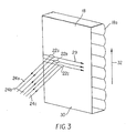
- each of the viewed images is generated by lines of images (also referred to as image lines) which have been interlaced at the spatial frequency of the lenticulas or the blocking line screen. Interlacing lines of each image with other images is referred to as interdigitation. A full set of such interdigitated image lines forms a lenticular image. Interdigitation can be better understood by using an example of four images used to form a composite image with a lenticular sheet that has three lenticulas. In this example, line 1 from each of the four images is in registration with the first lenticula; line 2 from each of the four images is in registration with the second lenticula; etc.
- Such lasers have two major problems. Firstly, they have an emitting aperture with a high aspect ratio and elliptical beam divergence. These characteristics make it hard to obtain a scanning spot with desired size and shape. Secondly, the emitting aperture size of the laser and hence the spot size at the recording material in any direction is inversely proportional to the amount of laser power in this direction. However, it is desired that a laser thermal printer has a high power density, i.e., that it has both the maximum power and the smallest possible spot size. Because a multimode laser produces a spot size that is long (large spot size in one dimension), the laser power is spread across the length of the spot, resulting in low power density.
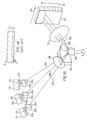
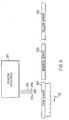
- the lasers 10a, 10b and 10c are being current modulated according to the image data to properly modulate the intensity of the laser beams 24a, 24b and 24c.
Landscapes
- Physics & Mathematics (AREA)
- Optics & Photonics (AREA)
- Engineering & Computer Science (AREA)
- Textile Engineering (AREA)
- Health & Medical Sciences (AREA)
- General Health & Medical Sciences (AREA)
- General Physics & Mathematics (AREA)
- Vascular Medicine (AREA)
- Manufacturing & Machinery (AREA)
- Mechanical Optical Scanning Systems (AREA)
- Electronic Switches (AREA)
- Laser Beam Printer (AREA)
- Laser Beam Processing (AREA)
- Lasers (AREA)
- Facsimile Scanning Arrangements (AREA)
Claims (6)
- Verfahren zum Drucken eines Bildes auf ein Linsenraster mit Zylinderlinsen, die eine Linearachse aufweisen, welche eine Länge der Zylinderlinsen definiert, mit einem Drucker, der einen Scanner aufweist, welcher einen durch eine Emissionsöffnung eines Multimode-Lasers erzeugten, polarisierten Multimode-Laserstrahl verwendet, wobei das Verfahren folgende Schritte umfasst:Bereitstellen eines Druckers mit einem Abtastelement (40), das eine Schnellabtastrichtung und eine Langsamabtastrichtung aufweist, sowie einem Multimode-Laser (10), der einen Multimode-Laserstrahl emittiert und eine Emissionsöffnung (12) mit einem langen Querschnitt und einem kurzen Querschnitt aufweist;Verändern der Polarisation eines Teils des Multimode-Laserstrahls, so dass der Multimode-Laserstrahl einen ersten Teil mit einer ersten Polarisation und einen zweiten Teil mit einer anderen Polarisation aufweist;wenigstens teilweise Überlagern des zweiten Teils des Multimode-Laserstrahls mit dem ersten Teil des Multimode-Laserstrahls, wodurch ein überlagerter Laserstrahl gebildet wird;Bilden eines Schreibpunktes mit dem überlagerten Laserstrahl;Führen des überlagerten Laserstrahls entlang einer Abtastzeile quer über das Linsenrastermaterial, so dass die Schnellabtastrichtung dem langen Querschnitt der Emissionsöffnung entspricht und entlang der Länge der Zylinderlinsen liegt; undUmsetzen des Linsenrasters in einer zur Länge der Zylinderlinsen senkrechten Richtung.
- Optische Druckvorrichtung (20; 60) mit:gekennzeichnet durcheinem Multimode-Laser (10), der einen Multimode-Laserstrahl entlang einer Bahn erzeugt;einem Abtastelement (40) mit einer Schnellabtastrichtung und einer Querabtastrichtung;einer Abtastlinse (50), die auf einem Aufzeichnungsmedium (30) mindestens einen Punkt erzeugt;einer Abbildungsoptik (64, 68);mindestens ein Polarisationsveränderungsglied (65), welches den Laserstrahl teilweise abfängt, um die Polarisation des durch das Glied (65) abgefangenen Laserlichts zu verändern, so dass ein entlang der besagten Bahn erzeugter Multimode-Laserstrahl einen Querschnitt mit zwei Teilen unterschiedlicher Polarisation aufweist;einen Polarisationskombinierer (69), der die beiden Teile des Multimode-Laserstrahls überlappt und dadurch einen konzentrierten Laserstrahl bildet;wobei das Abastelement (40) die Führung des konzentrierten Laserstrahls übernimmt, und wobei das Abtastelement nahe dem Polarisationskombinierer angeordnet ist;wobei die Abtastlinse (50) den durch das Abtastelement geführten, konzentrierten Laserstrahl abfängt;wobei der Laser eine Emissionsöffnung (12) mit einem langen Querschnitt und einem kurzen Querschnitt aufweist, wobei der lange Querschnitt einer Schnellabtastrichtung und der kurze Querschnitt einer Querabtastrichtung entspricht; undwobei die Abbildungsoptik (64, 68) auf dem Abtastelement ein Bild der Emissionsöffnung in mindestens einem Querschnitt erzeugt.
- Optische Druckvorrichtung nach Anspruch 2, dadurch gekennzeichnet, dass das Polarisationsveränderungsglied (65) eine Verzögerungsplatte ist.
- Optische Druckvorrichtung nach Anspruch 2, dadurch gekennzeichnet, dass der Polarisationskombinierer (69) ein Wollastonsches Prisma ist.
- Optische Druckvorrichtung nach Anspruch 2, gekennzeichnet durch eine anamorphotische Linse (63) mit einer Brechkraft, die in Querabtastrichtung stärker als in Abtastrichtung ist, wobei die anamorphotische Linse die Divergenz des Multimode-Laserstrahls in der Querabtastrichtung verringert.
- Optische Druckvorrichtung nach Anspruch 2, die mehrere Multimode-Laser (10a, 10b, 10c) aufweist, wobei(i) die Abbildungsoptik mehrere Sammellinsen (64a, 64b, 64c) aufweist, die jeweils zu einem der Multimode-Laser gehören; und(ii) die Emissionsöffnung (12) einem Aufzeichnungsmaterial in Querabtastrichtung optisch zugeordnet ist, und die Austrittsöffnung jeder der Sammellinsen (64a, 64b, 64c) dem Aufzeichnungsmaterial in Abtastrichtung zugeordnet ist.
Applications Claiming Priority (2)
| Application Number | Priority Date | Filing Date | Title |
|---|---|---|---|
| US175735 | 1998-10-20 | ||
| US09/175,735 US6191802B1 (en) | 1998-10-20 | 1998-10-20 | Optical apparatus and method for increasing intensity of multimode laser beams and a printer for printing lenticular images utilizing such laser beams |
Publications (3)
| Publication Number | Publication Date |
|---|---|
| EP0996022A2 EP0996022A2 (de) | 2000-04-26 |
| EP0996022A3 EP0996022A3 (de) | 2000-08-30 |
| EP0996022B1 true EP0996022B1 (de) | 2003-08-13 |
Family
ID=22641422
Family Applications (1)
| Application Number | Title | Priority Date | Filing Date |
|---|---|---|---|
| EP99203281A Expired - Lifetime EP0996022B1 (de) | 1998-10-20 | 1999-10-07 | Optische Vorrichtung und Verfahren zur Steigerung der Strahlungsintensität der Strahlen eines Multimodenlasers und Drucker zum Drucken eines linsenförmigen Bildes unter Verwendung solcher Laserstrahlen |
Country Status (4)
| Country | Link |
|---|---|
| US (1) | US6191802B1 (de) |
| EP (1) | EP0996022B1 (de) |
| JP (1) | JP4767380B2 (de) |
| DE (1) | DE69910326T2 (de) |
Families Citing this family (24)
| Publication number | Priority date | Publication date | Assignee | Title |
|---|---|---|---|---|
| AU2001213608A1 (en) * | 2000-11-03 | 2002-05-15 | Microvision, Inc. | Scanned display with switched feeds and distortion correction |
| US6781691B2 (en) * | 2001-02-02 | 2004-08-24 | Tidal Photonics, Inc. | Apparatus and methods relating to wavelength conditioning of illumination |
| WO2005010597A2 (en) * | 2003-07-16 | 2005-02-03 | Tidal Photonics, Inc. | Apparatus and methods relating to concentration and shaping of illumination |
| WO2005031433A1 (en) * | 2003-09-26 | 2005-04-07 | Tidal Photonics, Inc. | Apparatus and methods relating to color imaging endoscope systems |
| WO2005031292A1 (en) * | 2003-09-26 | 2005-04-07 | Tidal Photonics, Inc. | Apparatus and methods relating to enhanced spectral measurement systems |
| EP1709476A4 (de) * | 2003-09-26 | 2010-08-04 | Tidal Photonics Inc | Vorrichtungen und verfahren in bezug auf abbildungs-endoskopsysteme mit erweitertem dynamikumfang |
| US7406391B2 (en) * | 2004-09-20 | 2008-07-29 | Affymetrix, Inc. | System, method, and computer product for detection instrument calibration |
| US20080260242A1 (en) * | 2006-06-22 | 2008-10-23 | Tidal Photonics Inc. | Apparatus and methods for measuring and controlling illumination for imaging objects, performances and the like |
| DE102006050155B4 (de) * | 2006-10-21 | 2016-06-09 | Keming Du | Anordnungen zur Formung von Laserstrahlen |
| DE102008008232B4 (de) * | 2008-02-08 | 2011-04-14 | Realeyes Gmbh | Vorrichtung und Verfahren zum Belichten eines Fotomaterials |
| US8374818B2 (en) * | 2008-12-19 | 2013-02-12 | Affymetrix, Inc. | System, method and apparatus for calibrating inspection tools |
| US9767342B2 (en) | 2009-05-22 | 2017-09-19 | Affymetrix, Inc. | Methods and devices for reading microarrays |
| NL2004481C2 (nl) * | 2010-03-31 | 2011-10-04 | Sagem Identification B V | Werkwijze voor het vervaardigen van een driedimensionale afbeelding op basis van berekende beeldrotaties. |
| CN103448378B (zh) * | 2012-05-28 | 2015-10-28 | 日本电产科宝株式会社 | 激光刻印机 |
| JP6127714B2 (ja) * | 2013-05-23 | 2017-05-17 | セイコーエプソン株式会社 | レーザープロジェクター |
| CN103447693A (zh) * | 2013-07-18 | 2013-12-18 | 上海电机学院 | 一种微米纳米复合周期结构的制备方法 |
| US9599572B2 (en) * | 2014-04-07 | 2017-03-21 | Orbotech Ltd. | Optical inspection system and method |
| CN105467609B (zh) * | 2016-01-15 | 2017-12-15 | 南开大学 | 一种基于沃拉斯顿棱镜的空间角分复用全息术的参考光分束方法及其专用装置 |
| US10241292B2 (en) | 2016-12-09 | 2019-03-26 | Bae Systems Information And Electronic Systems Integration Inc. | Ultra-fast and mechanically stable zoom lens |
| KR102045476B1 (ko) * | 2018-06-28 | 2019-11-15 | 옵티시스 주식회사 | 광 커넥터 |
| CN112666196B (zh) * | 2019-10-16 | 2025-05-09 | 北航(四川)西部国际创新港科技有限公司 | 一种射线整合装置 |
| JP7552067B2 (ja) * | 2020-04-30 | 2024-09-18 | 船井電機株式会社 | 投光装置および車両用投光装置 |
| US20250102637A1 (en) * | 2022-01-18 | 2025-03-27 | Mitsubishi Electric Corporation | Light beam scanning device and distance measuring device |
| US20250328005A1 (en) * | 2022-10-19 | 2025-10-23 | Cornell University | Optical scanner and scanning method |
Citations (1)
| Publication number | Priority date | Publication date | Assignee | Title |
|---|---|---|---|---|
| EP0533377A2 (de) * | 1991-09-18 | 1993-03-24 | Konica Corporation | Bilderzeugungsverfahren |
Family Cites Families (14)
| Publication number | Priority date | Publication date | Assignee | Title |
|---|---|---|---|---|
| DE364549C (de) | 1914-03-24 | 1922-11-27 | Christian Meyer | Kammreiniger |
| JPS49607A (de) | 1972-04-21 | 1974-01-07 | ||
| AT364549B (de) * | 1976-03-13 | 1981-10-27 | Heidenhain Gmbh Dr Johannes | Anordnung mit einem laser und optischen mitteln zum aufweiten des laserstrahles in einer ebene |
| JPS5333847A (en) | 1976-09-06 | 1978-03-30 | Matsushita Electric Works Ltd | Pruner |
| JPS593781A (ja) | 1982-06-30 | 1984-01-10 | Fujitsu Ltd | スタテイツク型半導体記憶装置 |
| JPH0627904B2 (ja) * | 1986-02-06 | 1994-04-13 | 旭光学工業株式会社 | レーザービームの走査光学系 |
| JP2746790B2 (ja) | 1992-03-02 | 1998-05-06 | 富士写真フイルム株式会社 | 立体画像記録方法および立体画像記録装置 |
| JPH05289208A (ja) | 1992-04-15 | 1993-11-05 | Fuji Photo Film Co Ltd | 立体画像記録方法および立体画像記録装置 |
| JPH0822091A (ja) * | 1994-07-05 | 1996-01-23 | Canon Inc | 立体画像記録方法および装置ならびに立体画像形成体 |
| JP3546898B2 (ja) * | 1995-01-30 | 2004-07-28 | セイコーエプソン株式会社 | 光走査装置 |
| US5633736A (en) * | 1995-03-28 | 1997-05-27 | Eastman Kodak Company | Scan lens and an optical scanner system incorporating two deflectors |
| US5533152A (en) * | 1995-05-02 | 1996-07-02 | Eastman Kodak Company | Method and apparatus for coupling light emitted from a multi-mode laser diode array to a multi-mode optical fiber |
| US5808657A (en) * | 1996-06-17 | 1998-09-15 | Eastman Kodak Company | Laser printer with low fill modulator array and high pixel fill at a media plane |
| DE69800849T2 (de) | 1997-03-27 | 2001-11-15 | Mitsui Chemicals, Inc. | Halbleiterlaser-Lichtquelle und Festkörperlaser |
-
1998
- 1998-10-20 US US09/175,735 patent/US6191802B1/en not_active Expired - Lifetime
-
1999
- 1999-10-07 EP EP99203281A patent/EP0996022B1/de not_active Expired - Lifetime
- 1999-10-07 DE DE69910326T patent/DE69910326T2/de not_active Expired - Lifetime
- 1999-10-13 JP JP29155099A patent/JP4767380B2/ja not_active Expired - Fee Related
Patent Citations (1)
| Publication number | Priority date | Publication date | Assignee | Title |
|---|---|---|---|---|
| EP0533377A2 (de) * | 1991-09-18 | 1993-03-24 | Konica Corporation | Bilderzeugungsverfahren |
Also Published As
| Publication number | Publication date |
|---|---|
| DE69910326T2 (de) | 2004-06-09 |
| EP0996022A2 (de) | 2000-04-26 |
| JP4767380B2 (ja) | 2011-09-07 |
| US6191802B1 (en) | 2001-02-20 |
| DE69910326D1 (de) | 2003-09-18 |
| JP2000121974A (ja) | 2000-04-28 |
| EP0996022A3 (de) | 2000-08-30 |
Similar Documents
| Publication | Publication Date | Title |
|---|---|---|
| EP0996022B1 (de) | Optische Vorrichtung und Verfahren zur Steigerung der Strahlungsintensität der Strahlen eines Multimodenlasers und Drucker zum Drucken eines linsenförmigen Bildes unter Verwendung solcher Laserstrahlen | |
| US5311349A (en) | Unfolded optics for multiple row spatial light modulators | |
| US5105299A (en) | Unfolded optics for multiple row deformable mirror device | |
| US5325381A (en) | Multiple beam diode laser output scanning system | |
| US6177217B1 (en) | Method and apparatus for precise positioning of arrays with periodic structures | |
| JP3248604B2 (ja) | 視差情報を含むプリントを作る方法及びその装置 | |
| US5956070A (en) | Color xerographic printer with multiple linear arrays of surface emitting lasers with dissimilar polarization states and dissimilar wavelengths | |
| US6252621B1 (en) | Printing lenticular images | |
| US6069680A (en) | Flying spot laser printer apparatus and a method of printing suitable for printing lenticular images | |
| US6456435B1 (en) | Method and apparatus for adjusting spot size of one color component of a multiple color co-axial laser beam | |
| JPH06109993A (ja) | ラスター出力スキャナ | |
| US6200713B1 (en) | Method and apparatus for locating arrays with periodic structures relative to composite images | |
| US5995132A (en) | Method and apparatus for printing interdigitated images | |
| US4523838A (en) | Image forming apparatus | |
| JPH05221013A (ja) | マルチビームレーザプリンタ | |
| EP0782928B1 (de) | Farbxerographischer Drucker mit vielfachen linearen Reihen von oberflächenemittierenden Lasern mit gleichen Wellenlängen | |
| EP0040716A1 (de) | System zur Mehrfachbilderzeugung | |
| JP5021011B2 (ja) | レンチキュラ画像の印刷 | |
| JPS5968723A (ja) | 光変調素子 | |
| EP0781663B1 (de) | Farbxerographischer Drucker mit vielfachen linearen Reihen von oberflächenemittierenden Lasern mit verschiedenen Wellenlängen | |
| JPH0258014A (ja) | 光走査装置 | |
| JPH0192772A (ja) | マルチビームレーザスキャナ | |
| JPS6218532A (ja) | 走査光学系 | |
| JPS62151822A (ja) | レ−ザ走査系 |
Legal Events
| Date | Code | Title | Description |
|---|---|---|---|
| PUAI | Public reference made under article 153(3) epc to a published international application that has entered the european phase |
Free format text: ORIGINAL CODE: 0009012 |
|
| AK | Designated contracting states |
Kind code of ref document: A2 Designated state(s): DE FR GB |
|
| AX | Request for extension of the european patent |
Free format text: AL;LT;LV;MK;RO;SI |
|
| PUAL | Search report despatched |
Free format text: ORIGINAL CODE: 0009013 |
|
| AK | Designated contracting states |
Kind code of ref document: A3 Designated state(s): AT BE CH CY DE DK ES FI FR GB GR IE IT LI LU MC NL PT SE |
|
| AX | Request for extension of the european patent |
Free format text: AL;LT;LV;MK;RO;SI |
|
| RIC1 | Information provided on ipc code assigned before grant |
Free format text: 7G 02B 27/28 A, 7G 02B 27/22 B, 7B 41M 3/06 B, 7G 02B 27/09 B, 7H 04N 1/23 B |
|
| 17P | Request for examination filed |
Effective date: 20010125 |
|
| 17Q | First examination report despatched |
Effective date: 20010330 |
|
| AKX | Designation fees paid |
Free format text: DE FR GB |
|
| GRAH | Despatch of communication of intention to grant a patent |
Free format text: ORIGINAL CODE: EPIDOS IGRA |
|
| GRAH | Despatch of communication of intention to grant a patent |
Free format text: ORIGINAL CODE: EPIDOS IGRA |
|
| GRAA | (expected) grant |
Free format text: ORIGINAL CODE: 0009210 |
|
| AK | Designated contracting states |
Designated state(s): DE FR GB |
|
| REG | Reference to a national code |
Ref country code: GB Ref legal event code: FG4D |
|
| REF | Corresponds to: |
Ref document number: 69910326 Country of ref document: DE Date of ref document: 20030918 Kind code of ref document: P |
|
| ET | Fr: translation filed | ||
| PLBE | No opposition filed within time limit |
Free format text: ORIGINAL CODE: 0009261 |
|
| STAA | Information on the status of an ep patent application or granted ep patent |
Free format text: STATUS: NO OPPOSITION FILED WITHIN TIME LIMIT |
|
| 26N | No opposition filed |
Effective date: 20040514 |
|
| PGFP | Annual fee paid to national office [announced via postgrant information from national office to epo] |
Ref country code: GB Payment date: 20120925 Year of fee payment: 14 |
|
| PGFP | Annual fee paid to national office [announced via postgrant information from national office to epo] |
Ref country code: FR Payment date: 20121010 Year of fee payment: 14 |
|
| GBPC | Gb: european patent ceased through non-payment of renewal fee |
Effective date: 20131007 |
|
| PG25 | Lapsed in a contracting state [announced via postgrant information from national office to epo] |
Ref country code: GB Free format text: LAPSE BECAUSE OF NON-PAYMENT OF DUE FEES Effective date: 20131007 |
|
| REG | Reference to a national code |
Ref country code: FR Ref legal event code: ST Effective date: 20140630 |
|
| PG25 | Lapsed in a contracting state [announced via postgrant information from national office to epo] |
Ref country code: FR Free format text: LAPSE BECAUSE OF NON-PAYMENT OF DUE FEES Effective date: 20131031 |
|
| PGFP | Annual fee paid to national office [announced via postgrant information from national office to epo] |
Ref country code: DE Payment date: 20141028 Year of fee payment: 16 |
|
| REG | Reference to a national code |
Ref country code: DE Ref legal event code: R119 Ref document number: 69910326 Country of ref document: DE |
|
| PG25 | Lapsed in a contracting state [announced via postgrant information from national office to epo] |
Ref country code: DE Free format text: LAPSE BECAUSE OF NON-PAYMENT OF DUE FEES Effective date: 20160503 |