EP0996050A2 - Dispositif électronique - Google Patents
Dispositif électronique Download PDFInfo
- Publication number
- EP0996050A2 EP0996050A2 EP99400869A EP99400869A EP0996050A2 EP 0996050 A2 EP0996050 A2 EP 0996050A2 EP 99400869 A EP99400869 A EP 99400869A EP 99400869 A EP99400869 A EP 99400869A EP 0996050 A2 EP0996050 A2 EP 0996050A2
- Authority
- EP
- European Patent Office
- Prior art keywords
- electronic device
- power source
- module
- electricity
- functional module
- Prior art date
- Legal status (The legal status is an assumption and is not a legal conclusion. Google has not performed a legal analysis and makes no representation as to the accuracy of the status listed.)
- Withdrawn
Links
Images



Classifications
-
- G—PHYSICS
- G06—COMPUTING OR CALCULATING; COUNTING
- G06F—ELECTRIC DIGITAL DATA PROCESSING
- G06F1/00—Details not covered by groups G06F3/00 - G06F13/00 and G06F21/00
- G06F1/26—Power supply means, e.g. regulation thereof
- G06F1/263—Arrangements for using multiple switchable power supplies, e.g. battery and AC
Definitions
- the present invention generally relates to electronic devices, and more particularly to an electronic device supplied with driving power from an external power source or a built-in battery which is generally detachable.
- the portable computer is supplied with power from a battery. In order to improve the portability, it is required to miniaturize the battery and reduce consumption power.
- a conventional electronic device is equipped with a suspend/resume function of supplying power to the minimum parts of the device and breaking a supply of power to the other parts thereof so that power consumption can be reduced.
- the suspend/resume function is initiated when a suspend/resume button provided to the body of the electronic device is operated. Then, data in progress is saved and power is supplied to the minimum parts necessary to hold the data thus saved. The other parts of the device are in a paused state, so called, suspended state.
- the suspend/resume button is operated in the suspended state, the saved data is restored and the original state immediately prior to the suspended state is retrieved.
- the suspended state is initiated at the time of carrying the electronic device, so that a reduced amount of power can be consumed in the device.
- the conventional portable computer is designed to handle a functional unit or a module such as a LAN card or a modem card.
- a connector connected to a telephone line connected to a telephone network or a LAN line connected to a LAN is connected to a modular jack of the computer.
- commercial power source is also available.
- the functional unit such as a modem module of a card type (also referred to as a modem card) or a LAN module of a card type (also referred to as a LAN module) can be driven by the built-in battery without a supply of electricity from an external power source obtained via an AC-DC adapter.
- a modem module of a card type also referred to as a modem card
- a LAN module of a card type also referred to as a LAN module
- the LAN module has a comparatively high data transmission rate and thus consumes a large amount of energy.
- the driving capability of the battery is greatly reduced.
- a more specific object of the present invention is to provide an electronic device in which consumption of power of the built-in battery which is generally detachable.
- an electronic device comprising: a power supply circuit selectively providing an external power source or an internal power source; a first part determining whether the external power source is selected; a second part detecting a type of a functional unit used in the electronic device; and a third part which controls to supply the functional unit with electricity from one of the external and internal power sources on the basis of determination results obtained by the first and second parts.
- a further object of the present invention is to provide a method of controlling a supply of electricity to a functional unit in which the above-mentioned disadvantages are eliminated.
- This object of the present invention is achieved by a method of controlling a supply of electricity to a functional module detachably attached to an electronic device, said method comprises the steps of: determining whether an external power source is selected; detecting a type of a functional unit used in the electronic device; a third part which controls to supply the functional unit with electricity from the external power source or an internal power source on the basis of determination results obtained by the first and second parts.
- the electricity can be supplied from the external power source to the functional module of the given type when the external power is available.
- the functional module is not supplied with electricity therefrom.
- the functional module can be supplied with electricity from the internal power source in response to a given instruction.
- Fig. 1 is a perspective view of a portable computer which is an electronic device according to an embodiment of the present invention.
- An electronic device 100 is a pen-input type personal computer.
- a display part 102 and a state indication part 103 are provided to a display surface 101 of the electronic device 100.
- the display part 102 is arranged to the approximately whole display surface 101.
- the display part 102 includes a liquid crystal display 104 and a touch panel 105. Graphics information such as figures and characters is displayed on the liquid crystal display 104.
- the touch panel 105 is used to input information.
- the state indication part 103 includes a plurality of LEDs 103a - 103d, which indicate the respective operation states of the device, for example, the ON/OFF state of an external power source and the ON/OFF state of charging a battery built in the electronic device 100 in a detachable fashion.
- an AC-DC adapter connection port 111 To a right side surface 110 of the electronic device 100, there are provided an AC-DC adapter connection port 111, a USB (Universal Serial Bus) port 112, a communication connector port 113, a PC card slot 114, and a pen inlet port 115.
- An AC-DC adapter 116 is connected to the AC-DC adapter connection port 111, and an external power source is available via the AC-DC adapter 116.
- the USB port 112 is a port which conforms to the USB standards.
- a USB cable 117 is connected to the USB port 112, so that a peripheral device can be connected to the electronic device 100.
- the communication connector port 113 conforms to the RJ11.
- a connector 118 of telephone line or a LAN line which conforms to the RJ11 can be connected to the communication connector port 113.
- the PC card slot 114 conforms to the PCMCIA standard.
- a PC card 119 which conforms to the PCMCIA standard can be inserted into the PC card slot 114.
- a pen 120 can be inserted into and detached from the pen inlet port 115 and is used to operate the touch panel 104.
- a DC contact 112 and an expansion connector 113 are provided to a lower surface 121 of the electronic device 100.
- the DC contact 122 is connected to a DC power source when an expanded device (not shown) is connected to the electronic device 100.
- the expanded connector 113 is used to receive signals from the expanded device and output signals thereto.
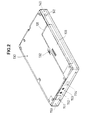
- Fig. 2 is a perspective view of the back surface of the electronic device 100. As shown in Fig. 2, a battery pack attaching part 131 and a battery pack lock 132 are provided to a back surface 130 of the electronic device 100.
- a battery pack 133 is attached to the battery pack attaching part 131.
- the battery lock 132 locks the battery pack 133, which can be detached from the battery pack attaching part 133 by unlocking the battery lock 132.
- a suspend/resume button 141 is arranged on an upper surface 140 of the electronic device 100 and is used to indicate a suspend/resume function.
- the IrDA port 151 is a communication port which conforms to the IrDA standard.
- the electronic device 100 can communicate with another device which has an IrDA port conforming to the IrDA standard.
- a voice signal can be applied to the microphone jack 153.
- a voice signal is output from the speaker 154.
- the electronic device 100 includes a CPU (controller) 161, a memory 162, a graphics LSI 163, bridge circuits 164 and 165, a PC card controller 166, an IrDA controller 167, a PCI bus 168, a ROM 169, and ISA bus 170, a sound controller 171, a power source connection control circuit 172, a power supply control circuit 173, a power supply circuit 174, a state setting circuit 175, a bus connection control part 176, one or a plurality of modules 177 and an HDD (Hard Disk Drive) 178.
- a CPU central processing unit
- the CPU 161 executes a process in accordance with programs stored in the ROM 169 and the HDD 178.
- the memory 162 is used as a working area of the CPU 161.
- the graphics LSI device 163 executes graphics processing.
- the bridge circuit 164 connects the CPU 161, the memory 162 and the graphics LSI device 163 to the PCI bus 168.
- the bridge circuit 165 connects the PCI bus 168 and the ISA bus 170.
- the sound controller 171 and the touch panel 105 are connected to the ISA bus 170.
- the microphone jack 152, the headphone jack 153 and the speaker 154 are connected to the sound controller 171, which performs a variety of voice processing.
- the USB port 112 is connected to the bridge circuit 165, which makes a connection with a device which conforms to the USB standard.
- the power source connection control circuit 172 is connected to the PCI bus 168, and controls the power supply control circuit 173 and the bus connection control part 176 in response to a power on instruction supplied via the PCI bus 168, as will be described later. Further, the circuit 172 controls a set/reset operation on each of the modules 177.
- the power supply control circuit 173 includes power supply control circuits 173-1 - 173-n respectively provided to modules and circuits.
- the circuits 173-1 - 173-n are connected to the corresponding modules and circuits, and are turned on or off in response to power supply control signals a-1 - a-n from the power source connection control circuit 172. Hence, the modules and the circuits are supplied with electricity or not.
- the bus connection control part 176 is connected between the modules 177 and the PCI bus 168, and connects or disconnects the modules 177 to or from the PCI bus 168 in response to a bus connection control signal supplied from the power source connection control circuit 172.
- the state setting circuit 175 includes a power source state register 175a and a module register 175b.
- a flag is set in the power source state register 175a, and indicates whether electricity is supplied from an internal power source of the battery pack 133 or an external power source of the AC-DC adapter 116.
- a flag is set in the module register 175b, and indicates whether the module 177 connected to the electronic device 100 is a LAN module or a modem module.
- the power source state register 175a and the module register 175b of the state setting circuit 175 are referred to by the BIOS, and the power source connection control circuit 172 is thus controlled.
- Fig. 4 is a flowchart of a connecting process which is carried out at the time of activating the electronic device 100.
- a module connecting process is carried out each time the electronic device 100 is activated. That is, the module connecting process is carried out at the time of the power on or the suspend/resume.
- the BIOS or the CPU 161 refers to the module register 175b of the module register 175b and determines whether the connected module 177 is a LAN module (LAN card) or not (step S1-1). In other words, this step is intended to detect the type of the functional unit attached to the electronic device 100.
- the CPU 161 refers to the register 175a of the state setting circuit 175, and determines whether the electricity is supplied from the external power source, that is, that from the AC-DC adapter 116 or the internal power source of the battery pack 133 (step S1-2).
- step S1-2 shows that the electricity is supplied from the AC-DC adapter 116
- the power on instruction directed to the LAN module is issued to the power source connection control circuit 172 (step S1-3).
- step S1-2 When it is determined at step S1-2 that the electricity is supplied from the battery pack 133, the process is ended without issuing the power instruction directed to the module 177.
- step S1-4 the register 175b of the state setting circuit 175 is referred to and it is determined whether the connected module 177 is a modem module or not (step S1-4).
- step S1-4 shows that the connected module 177 is a modem module
- the register 175a of the state setting circuit 175 is referred to and it is determined whether the electricity is supplied from the external power source, that is, from the AC-DC adapter 116 or the internal power source from the battery pack 133 (step S1-5).
- step S1-5 When it is determined at step S1-5 that the electricity is supplied from the AC-DC adapter 116, the CPU 161 issues the power on instruction directed to the modem module to the power source connection control circuit 172 (step S1-6).
- step S1-5 When it is determined at step S1-5 that the electricity is supplied from the battery pack 133, the CPU 161 does not issue the power on instruction directed to the module 177 and ends the process.
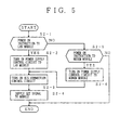
- the power source connection control circuit 172 monitors receipt of the power on instruction directed to the LAN module (step S2-1). When the power on instruction directed to the LAN module is received, the power source connection control circuit 172 turns on the power supply control circuit 173-1 provided to the LAN module (step S2-2). When the power supply control circuit 173-1 is turned on at step S2-2, the LAN module connected as the module 177 is supplied with electricity.
- the power source connection control circuit 172 turns on the bus connection control circuit 176 (step S2-3).
- the bus connection control circuit 176 is turned on, the module 177 and the PCI bus 178 are connected together.
- the power source connection control circuit 172 supplies the set signal to the module 177, which is thus switched to the set state (step S2-4).
- the power source connection control circuit 172 determines that the power on instruction received at step S2-1 is directed to the modem module (step S2-5).
- the power source connection control circuit 172 turns on the power supply control circuit 173-2 provided to the modem module (step S2-6).
- the circuit 173-2 provided to the modem module is turned on at step S2-6, electricity is supplied to the modem module connected as the module 177.
- step S2-6 When the power supply control circuit 173-2 provided to the modem module is turned on at step S2-6 and electricity is supplied thereto, the power source connection control circuit 172 executes step S2-3 at which the module 177 and the PCI bus 178 are connected.
- the power source connection control circuit 172 supplies the set signal to the module 177 at step S2-4, so that the module 177 is switched to the set state.
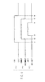
- Fig. 6 is a timing chart of the module connection process carried out in the electronic device 100. More particularly, Fig. 6(A) shows power on to the module, Fig. 6(B) shows the state of the connection between the PCI bus 168 and the module 177 in the bus connection control part 176, and Fig. 6(C) shows the set/reset state of the module 177.
- the bus connection control part 176 is controlled by step S2-3 shown in Fig. 5, and the module 177 is connected to the PCI bus 168 at time t2.
- the reset signal is supplied to the module 177 from the power source connection control circuit 172 by the process of step S2-4. Then, the module 177 is reset at time t3 and becomes operable.
- the module 177 is released from the set state at time t4, and the module 177 is disconnected from the PCI bus 178 by the bus connection control part 176 at time t5. Then, the electricity supplied to the module 177 by the power supply control circuit 172 is stopped. Hence, it is possible to avoid occurrence of a situation in which the module 177 that is in the set state (operable state) is abruptly connected to the PCI bus 178 and to prevent another operation on the PCI bus 178 from being affected.
- a supply of power or electricity to the module 177 is controlled by determining, at the time of activating a given process such as power on or resume, whether electricity is supplied from the battery pack 133 from the external power source via the AC-DC adapter 116. Hence, while the electronic device 100 is being driven, the supply of power to the module 177 is stopped and power consumed in the electronic device 100 can be reduced.
Landscapes
- Engineering & Computer Science (AREA)
- Theoretical Computer Science (AREA)
- Power Engineering (AREA)
- Physics & Mathematics (AREA)
- General Engineering & Computer Science (AREA)
- General Physics & Mathematics (AREA)
- Power Sources (AREA)
- Semiconductor Integrated Circuits (AREA)
- Dc-Dc Converters (AREA)
- Direct Current Feeding And Distribution (AREA)
Applications Claiming Priority (2)
| Application Number | Priority Date | Filing Date | Title |
|---|---|---|---|
| JP10297330A JP2000122756A (ja) | 1998-10-19 | 1998-10-19 | 電子機器 |
| JP29733098 | 1998-10-19 |
Publications (2)
| Publication Number | Publication Date |
|---|---|
| EP0996050A2 true EP0996050A2 (fr) | 2000-04-26 |
| EP0996050A3 EP0996050A3 (fr) | 2004-04-07 |
Family
ID=17845128
Family Applications (1)
| Application Number | Title | Priority Date | Filing Date |
|---|---|---|---|
| EP99400869A Withdrawn EP0996050A3 (fr) | 1998-10-19 | 1999-04-09 | Dispositif électronique |
Country Status (4)
| Country | Link |
|---|---|
| US (1) | US6338143B1 (fr) |
| EP (1) | EP0996050A3 (fr) |
| JP (1) | JP2000122756A (fr) |
| CN (1) | CN1136490C (fr) |
Cited By (2)
| Publication number | Priority date | Publication date | Assignee | Title |
|---|---|---|---|---|
| GB2384334A (en) * | 2002-01-19 | 2003-07-23 | Inc Technologies | Control module and expansion board, with a control processor module, for connection to a motherboard bus |
| WO2010063681A1 (fr) | 2008-12-03 | 2010-06-10 | Sinitec Vertriebsgesellschaft Mbh | Ensemble d'appareils comprenant un appareil électronique et un bloc d'alimentation, ainsi que procédé pour la commutation d'un bloc d'alimentation |
Families Citing this family (14)
| Publication number | Priority date | Publication date | Assignee | Title |
|---|---|---|---|---|
| KR100306697B1 (ko) * | 1998-07-23 | 2001-11-30 | 윤종용 | 유니버설시리얼버스의전원공급을제어하는휴대용컴퓨터시스템및그제어방법 |
| JP2001184147A (ja) * | 1999-12-27 | 2001-07-06 | Sanyo Electric Co Ltd | 携帯電子機器 |
| KR100422248B1 (ko) * | 2001-05-07 | 2004-03-12 | 삼성전자주식회사 | 컴퓨터 및 컴퓨터의 데이터 통신 제어 방법 |
| JP3837312B2 (ja) * | 2001-09-18 | 2006-10-25 | インターナショナル・ビジネス・マシーンズ・コーポレーション | コンピュータ装置、無線通信モジュール、無線通信モジュールの制御方法、プログラム |
| JP3974510B2 (ja) | 2002-12-11 | 2007-09-12 | インターナショナル・ビジネス・マシーンズ・コーポレーション | コンピュータ装置、電力管理方法、およびプログラム |
| TWI289677B (en) * | 2003-10-21 | 2007-11-11 | Via Tech Inc | Method and apparatus for testing a bridge circuit |
| US8683426B2 (en) * | 2005-06-28 | 2014-03-25 | The Mathworks, Inc. | Systems and methods for modeling execution behavior |
| US8793602B2 (en) | 2004-01-15 | 2014-07-29 | The Mathworks, Inc. | System and method for scheduling the execution of model components using model events |
| JP5385500B2 (ja) * | 2006-03-23 | 2014-01-08 | セミコンダクター・コンポーネンツ・インダストリーズ・リミテッド・ライアビリティ・カンパニー | 信号処理装置 |
| JP4669803B2 (ja) * | 2006-03-23 | 2011-04-13 | 三洋電機株式会社 | 集積回路及びそれを用いた信号処理装置 |
| CN101641659B (zh) * | 2006-12-27 | 2012-11-14 | 电子数据控制控股有限公司 | 个人计算机功率控制方法和设备 |
| KR101391758B1 (ko) * | 2007-01-11 | 2014-05-07 | 삼성전자 주식회사 | 배터리 모듈과 컴퓨터 시스템 및 그 전원공급방법 |
| US20110163964A1 (en) * | 2010-01-07 | 2011-07-07 | Yen-Lung Tsai & Tsung-Chieh CHO | Dual type touch display device |
| CN113937851B (zh) * | 2021-09-30 | 2023-05-09 | 厦门盈趣科技股份有限公司 | 一种移动机器人的节能电源系统、方法及移动终端 |
Family Cites Families (7)
| Publication number | Priority date | Publication date | Assignee | Title |
|---|---|---|---|---|
| JPH0291253A (ja) * | 1988-09-26 | 1990-03-30 | Orishige:Kk | インレイ・パイル編み地、及びその製編装置 |
| US5167024A (en) | 1989-09-08 | 1992-11-24 | Apple Computer, Inc. | Power management for a laptop computer with slow and sleep modes |
| JP2776105B2 (ja) * | 1992-01-07 | 1998-07-16 | 三菱電機株式会社 | 電子機器及び電子機器への電力供給方法 |
| US5442794A (en) * | 1993-12-01 | 1995-08-15 | Advanced Micro Devices, Inc. | Disable technique employed during low battery conditions within a portable computer system |
| US5623596A (en) * | 1994-05-09 | 1997-04-22 | Apple Computer, Inc. | Power fault protection in a computer system having multiple power supplies |
| KR0148053B1 (ko) * | 1995-05-12 | 1998-09-15 | 김광호 | 액정 표시 소자의 후면 광원 구동 제어 장치 및 그 방법 |
| US6035408A (en) * | 1998-01-06 | 2000-03-07 | Magnex Corp. | Portable computer with dual switchable processors for selectable power consumption |
-
1998
- 1998-10-19 JP JP10297330A patent/JP2000122756A/ja active Pending
-
1999
- 1999-04-07 US US09/287,265 patent/US6338143B1/en not_active Expired - Fee Related
- 1999-04-09 EP EP99400869A patent/EP0996050A3/fr not_active Withdrawn
- 1999-04-22 CN CNB991052471A patent/CN1136490C/zh not_active Expired - Fee Related
Cited By (4)
| Publication number | Priority date | Publication date | Assignee | Title |
|---|---|---|---|---|
| GB2384334A (en) * | 2002-01-19 | 2003-07-23 | Inc Technologies | Control module and expansion board, with a control processor module, for connection to a motherboard bus |
| GB2384334B (en) * | 2002-01-19 | 2004-07-07 | Inc Technologies | Kiosk technology kit |
| WO2010063681A1 (fr) | 2008-12-03 | 2010-06-10 | Sinitec Vertriebsgesellschaft Mbh | Ensemble d'appareils comprenant un appareil électronique et un bloc d'alimentation, ainsi que procédé pour la commutation d'un bloc d'alimentation |
| US8686588B2 (en) | 2008-12-03 | 2014-04-01 | Fujitsu Technology Solutions Intellectual Property Gmbh | Device arrangement comprising an electronic device and a power adapter and method for connecting a power adapter |
Also Published As
| Publication number | Publication date |
|---|---|
| JP2000122756A (ja) | 2000-04-28 |
| US6338143B1 (en) | 2002-01-08 |
| CN1136490C (zh) | 2004-01-28 |
| CN1251432A (zh) | 2000-04-26 |
| EP0996050A3 (fr) | 2004-04-07 |
Similar Documents
| Publication | Publication Date | Title |
|---|---|---|
| US6338143B1 (en) | Electronic device | |
| US7197584B2 (en) | Removable personal digital assistant in a dual personal computer/personal digital assistant computer architecture | |
| EP2521953B1 (fr) | Alimentation d'un accessoire pendant la veille prolongée d'un dispositif informatique portable | |
| US7219240B2 (en) | Monitor and method for controlling power-on and power-off of host computer | |
| US5347630A (en) | Computer system having a detachable display | |
| US6742070B2 (en) | Function-expansion device detachably connecting electronic equipment | |
| TW470876B (en) | Launch key, low power CD-ROM player for portable computers | |
| US7116322B2 (en) | Display apparatus and controlling method thereof | |
| USRE42052E1 (en) | System and method for managing power of peripheral communications by automatically closing communications channel immediately after finishing a communication with a peripheral device | |
| JP2010108423A (ja) | 情報処理装置 | |
| KR100204695B1 (ko) | 휴대형 컴퓨터용 도킹 장치 및 그 제어 방법 | |
| EP1293876B1 (fr) | Système de traitement d'informations modulaires | |
| JP3294512B2 (ja) | 電子機器およびその電源処理方法 | |
| US20090160404A1 (en) | Information processing apparatus | |
| JPH0997126A (ja) | 拡張ユニットおよびこの拡張ユニットに接続可能なコンピュータ | |
| JPH0997127A (ja) | コンピュータシステム | |
| CN101620463A (zh) | 信息处理设备和唤醒控制方法 | |
| JP4387493B2 (ja) | コンピュータシステムおよび同システムの制御方法 | |
| US6766392B2 (en) | Electronic apparatus, control circuit for electronic apparatus, and method of controlling electronic apparatus | |
| JPH11345051A (ja) | コンピュータシステム | |
| JPH1165720A (ja) | コンピュータおよびコンピュータシステム | |
| JP2007102370A (ja) | 電子機器、該電子機器にて実行される動作モード制御方法および電子機器システム | |
| CN121657848A (zh) | Usb控制器、芯片、usb电源管理系统、供电方法及存储介质 | |
| JPWO1998058307A1 (ja) | 個人用携帯情報端末装置 | |
| AU2013203563A1 (en) | Providing power to an accessory during portable computing device hibernation |
Legal Events
| Date | Code | Title | Description |
|---|---|---|---|
| PUAI | Public reference made under article 153(3) epc to a published international application that has entered the european phase |
Free format text: ORIGINAL CODE: 0009012 |
|
| AK | Designated contracting states |
Kind code of ref document: A2 Designated state(s): AT BE CH CY DE DK ES FI FR GB GR IE IT LI LU MC NL PT SE |
|
| AX | Request for extension of the european patent |
Free format text: AL;LT;LV;MK;RO;SI |
|
| PUAL | Search report despatched |
Free format text: ORIGINAL CODE: 0009013 |
|
| AK | Designated contracting states |
Kind code of ref document: A3 Designated state(s): AT BE CH CY DE DK ES FI FR GB GR IE IT LI LU MC NL PT SE |
|
| AX | Request for extension of the european patent |
Extension state: AL LT LV MK RO SI |
|
| 17P | Request for examination filed |
Effective date: 20040929 |
|
| AKX | Designation fees paid |
Designated state(s): DE FR GB |
|
| STAA | Information on the status of an ep patent application or granted ep patent |
Free format text: STATUS: THE APPLICATION IS DEEMED TO BE WITHDRAWN |
|
| 18D | Application deemed to be withdrawn |
Effective date: 20080221 |