EP0996099A2 - Elément semi-conducteur électroluminescent pour le test de caractéristiques de sécurité luminescentes - Google Patents
Elément semi-conducteur électroluminescent pour le test de caractéristiques de sécurité luminescentes Download PDFInfo
- Publication number
- EP0996099A2 EP0996099A2 EP99120299A EP99120299A EP0996099A2 EP 0996099 A2 EP0996099 A2 EP 0996099A2 EP 99120299 A EP99120299 A EP 99120299A EP 99120299 A EP99120299 A EP 99120299A EP 0996099 A2 EP0996099 A2 EP 0996099A2
- Authority
- EP
- European Patent Office
- Prior art keywords
- radiation
- solid
- electroluminescent
- security features
- wavelength range
- Prior art date
- Legal status (The legal status is an assumption and is not a legal conclusion. Google has not performed a legal analysis and makes no representation as to the accuracy of the status listed.)
- Granted
Links
- 239000004065 semiconductor Substances 0.000 title claims description 18
- 238000012360 testing method Methods 0.000 title description 17
- 238000000034 method Methods 0.000 claims abstract description 20
- 230000005855 radiation Effects 0.000 claims description 40
- 230000003287 optical effect Effects 0.000 claims description 7
- 239000002131 composite material Substances 0.000 claims description 2
- 238000001514 detection method Methods 0.000 claims description 2
- 238000005265 energy consumption Methods 0.000 claims description 2
- 230000005284 excitation Effects 0.000 claims description 2
- 210000001525 retina Anatomy 0.000 claims description 2
- 239000007787 solid Substances 0.000 claims 9
- 239000003086 colorant Substances 0.000 description 11
- 230000008901 benefit Effects 0.000 description 8
- 239000000463 material Substances 0.000 description 7
- 230000008859 change Effects 0.000 description 5
- 238000013461 design Methods 0.000 description 5
- 230000000694 effects Effects 0.000 description 5
- 238000012795 verification Methods 0.000 description 5
- 238000006243 chemical reaction Methods 0.000 description 4
- 230000001419 dependent effect Effects 0.000 description 3
- 238000005516 engineering process Methods 0.000 description 3
- 238000004020 luminiscence type Methods 0.000 description 3
- 230000003595 spectral effect Effects 0.000 description 3
- PPBRXRYQALVLMV-UHFFFAOYSA-N Styrene Chemical compound C=CC1=CC=CC=C1 PPBRXRYQALVLMV-UHFFFAOYSA-N 0.000 description 2
- 230000004888 barrier function Effects 0.000 description 2
- 238000011161 development Methods 0.000 description 2
- 238000004519 manufacturing process Methods 0.000 description 2
- 239000000203 mixture Substances 0.000 description 2
- 230000008569 process Effects 0.000 description 2
- 230000011514 reflex Effects 0.000 description 2
- 238000001228 spectrum Methods 0.000 description 2
- 238000012546 transfer Methods 0.000 description 2
- NLHHRLWOUZZQLW-UHFFFAOYSA-N Acrylonitrile Chemical compound C=CC#N NLHHRLWOUZZQLW-UHFFFAOYSA-N 0.000 description 1
- 240000001913 Atriplex hortensis Species 0.000 description 1
- 208000020564 Eye injury Diseases 0.000 description 1
- 239000004904 UV filter Substances 0.000 description 1
- 230000006378 damage Effects 0.000 description 1
- 230000003247 decreasing effect Effects 0.000 description 1
- 230000003203 everyday effect Effects 0.000 description 1
- 230000036541 health Effects 0.000 description 1
- 238000005286 illumination Methods 0.000 description 1
- 238000001746 injection moulding Methods 0.000 description 1
- 238000009434 installation Methods 0.000 description 1
- 210000003205 muscle Anatomy 0.000 description 1
- 210000001328 optic nerve Anatomy 0.000 description 1
- 238000003825 pressing Methods 0.000 description 1
- 230000000717 retained effect Effects 0.000 description 1
- 239000000243 solution Substances 0.000 description 1
- 239000004575 stone Substances 0.000 description 1
- 238000003860 storage Methods 0.000 description 1
- 238000010998 test method Methods 0.000 description 1
- 229920001169 thermoplastic Polymers 0.000 description 1
- 239000004416 thermosoftening plastic Substances 0.000 description 1
- 230000001960 triggered effect Effects 0.000 description 1
- 238000012800 visualization Methods 0.000 description 1
- XLYOFNOQVPJJNP-UHFFFAOYSA-N water Substances O XLYOFNOQVPJJNP-UHFFFAOYSA-N 0.000 description 1
Images


Classifications
-
- G—PHYSICS
- G07—CHECKING-DEVICES
- G07D—HANDLING OF COINS OR VALUABLE PAPERS, e.g. TESTING, SORTING BY DENOMINATIONS, COUNTING, DISPENSING, CHANGING OR DEPOSITING
- G07D7/00—Testing specially adapted to determine the identity or genuineness of valuable papers or for segregating those which are unacceptable, e.g. banknotes that are alien to a currency
- G07D7/06—Testing specially adapted to determine the identity or genuineness of valuable papers or for segregating those which are unacceptable, e.g. banknotes that are alien to a currency using wave or particle radiation
- G07D7/12—Visible light, infrared or ultraviolet radiation
- G07D7/1205—Testing spectral properties
Definitions
- the present invention relates to a method and an apparatus for Verification of luminescent security features using UV and Luminescent diodes (LEDs) emitting infrared light.
- LEDs UV and Luminescent diodes
- Luminescent security features for the value and security area have been used for a long time. To the security features on the affected security and valuables are attached with Reliable efforts to make acceptable efforts visible have already been varied Efforts have been made to implement appropriate procedures and devices to develop.
- luminescent security features are not yet visible matured to the extent that it is easy and uncomplicated to use enable reliable detection of the security features.
- the present invention is therefore based on the object of a method and a device for the verification of luminescent Security features, which in and / orr on value and Security documents and objects are arranged, the Application of the device and control of the concerned Security features simple, uncomplicated, repeatable at any time, without health damage to the user and those in the immediate Surrounding people is feasible, and the control procedure with the control device without line-dependent energy and Information transfer should be executable.
- luminescent material with imperceptible afterglow which is called fluorescent
- the second type of luminescent material, which has the effect of a Afterglow is called phosphorizing.
- the energy supply for the operation of the LEDs used can due to the low power consumption compared to the tubes, definitely via batteries, so-called button cells. Through this Power supply, it is guaranteed that the test equipment for Verification of luminescent security elements regardless of location can be done. Another advantage is that the test facility can be transported easily and based on the small dimensions and associated light weight available to everyone at all times can stand by this testing facility, like other everyday utensils Is always at hand.
- diodes in one Composite are arranged so that they form a bundle which roughly approximately the same beam direction its at least partially outside the radiate visible radiation in the visible wavelength range.
- an essential safety feature of the present Invention is at least one among this bundle of light emitting diodes Light-emitting diode arranged, which emits light in the visible range, whereby a first security feature, namely an optical operating display, Is used.
- a first security feature namely an optical operating display
- Another additional safety device from The present invention is that optionally an additional acoustic operating display of those working in the invisible spectral range LEDs indicate.
- Another advantage of the present invention over those previously Fluorescent lamps used is that the life of the LEDs are a multiple of the life of fluorescent lamps. Especially when the fluorescent lamps are switched on and off frequently Lifespan of this is significantly reduced, creating an average Lifespan of approximately 1000 operating hours for the fluorescent lamps is far below. The lifespan of the LEDs, however, is one Multiples of 1000 operating hours.
- UV-LED's UV light-emitting diodes
- the UV LEDs are in their design and in their electrical characteristics comparable to conventional light emitting diodes. LEDs for the visible wavelength range (wavelength 400 nanometers to 700 nanometers) and for the near infrared range (IR; wavelength 700 Nanometers to 1000 nanometers) have been in use for a long time. You will be in the technology above all as display elements (blue, green, yellow and red LEDs) or used in remote controls, light barriers (IR LEDs). The Desire for ever shorter wavy LEDs is justified by the fact that the optical storage density of data, for example on CD or DVD decreasing wavelength is getting bigger.
- LEDs work in a wavelength range of 370 nanometers and thus have a wavelength similar to that of commercially available UV lamps (Wavelength 375 nanometers).
- Another advantage of the light emitting diodes over the fluorescent tubes is in that the light emitting diodes immediately provide their full optical power as soon as they are energized.
- the fluorescent tube however, it takes a certain amount of time to ignite the gas and thus to achieve their luminosity and operational readiness.
- In order to the disadvantage of the waiting time between are automatically connected Switch-on time and the first operational state of the fluorescent tube as well as the disadvantage of the significantly higher power consumption.
- a power supply is required for the correct operation of these LEDs between 3.5 volts and 4.5 volts necessary.
- This power supply can using appropriately sized batteries for a satisfactorily long time Service life can be achieved.
- a consistently intense luminosity can be achieved by using a Constant current source for the supply of the UV LEDs can be achieved. Care the transistors used to ensure that the UV LEDs are always the same Voltage drops, which results in constant luminosity when in use. By using such a constant current source, it is also possible Use battery voltages above 4.5 volts, which are caused by the electronics the correspondingly required values are limited. With the previously specified Data thus generates a power consumption of approximately 10 milliamperes. Under These operating conditions have a lifespan of approximately 2000 Operating hours according to the manufacturer's specification. When using conventional alkaline batteries of the type LR44 (1.5 volts) result in a Operating time of approximately 12 hours. Set one for reviewing one Security and value document for a period of 10 seconds a number of test operations, which is 4320 operations.
- the present invention provides that the suggestion for delivery luminescent radiation caused by the infrared or ultraviolet Radiation, by pulse method for the operating voltage supplied used LED's is influenced so that different colors the correspondingly excited luminescence security features on the value and Sign off security documents and objects. Background this changing color spectrum of the luminescent features emitted radiation is the superposition of emitted luminescent Radiation from different frequency ranges due to use of different colors, the individual decay constants of different Order of magnitude. It is advantageous to use luminescent colors which have significantly different decay constants.
- the ultraviolet or infrared radiation which is released from the semiconductor solid-state elements, is therefore directly from dependent on the voltage, since this immediately gives its full radiation power when applied of a corresponding voltage and this until the switch-off time maintained.
- the luminescent security features in the Form of the supplied operating voltage from the infrared and ultraviolet Radiation irradiated. Due to the intermittent and / or modulated form of this Power supply are now the retroreflective characteristics of the for Security features used luminescent colors depending on their Decay constants recorded by the eye.
- the color A is green and the color B is blue pulsed power supply the reflection of the security elements the Color blue / green.
- the voltage supply will change over time in the cycle the color A - i.e. green - always between the voltage switched on and off weaker and the color blue would remain constant. This modulation can go so far be driven until the reflection of the color green has completely subsided is. In this case the color would now be blue, based on its large size Decay constant, still emit visible radiation.
- the present invention now provides that the modulation method for Operating voltage of the LED's are optional when checking the value and Security documents and objects vary. This allows the whole Frequency spectrum of the applied security features can be checked. This is shown by a change in the retroreflective colors, which change results from the sum of the retroreflective frequencies.
- Another alternative power supply results from the use of a DC / DC inverter.
- This IC is able to measure the voltage of a battery multiply. In this way it is possible to add electronics for the UV LEDs develop that only needs one or two LR44 batteries.
- This embodiment is an alternative to the embodiment with the Constant current source.
- the core housing is made of acrylonitrile butodiene styrene copylymere (ABS) in the thermoplastic injection molding process.
- ABS acrylonitrile butodiene styrene copylymere
- elastomeric elements are used so that the function of the test facility through Floor traps from hip or shoulder height, even on hard floors, such as Stone floors or the like, is not affected.
- the high breaking strength of the test facility achieved in this way is another Security feature of the present invention.
- Another feature of Safe operation of the test equipment lies in the fact that the housing design is designed such that it is closed to protect against splashing water.
- the UV LEDs are arranged in the housing in such a way that they are scratched by protruding elements is avoided and so the opening angle of approximately 10 ° of the emitting UV and / or IR light is retained at all times.
- This stationary UV LED lamp comes with several LEDs are equipped to provide a uniform, intensive illumination guarantee.
- This verifier can optionally be equipped with a UV filter his. This filter can remove the annoying, visible, blue light components of the UV LEDs reduce and thus an improved visibility of the luminescence enable. In addition, the color fastness of the luminescence compared to that restored with UV lamp.
- a proximity sensor In order to enable a corresponding value and security product or object to be recognized when it is brought into the control position, it is provided to install a proximity sensor.
- This proximity sensor switches on the power supply for the LEDs when a value and security product or object is detected. This enables the control process described above to be triggered.
- the UV-LED verifier is therefore equipped with a sensor that detects whether a security document to be checked is under the device.
- the UV LEDs are only switched on in this case.
- Such a sensor could be implemented using a simple light barrier.
- the advantage of this solution is that the UV LEDs are only switched on when they are needed.
- the service life is significantly increased in this operation and exceeds that of a stationary UV lamp, with which such operation is not possible, many times over.
- UV LEDs In addition to those under UV light luminescent Security features are also increasingly used feature materials that under irradiation with infrared light in the visible lighting area (down-conversion or anti-stocks) converge. A combination of UV and IR LEDs is therefore sensible, since it checks both security features in this way can be.
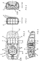
- FIG. 1 shows a UV-IR-LED pointer, which has 5 UV-LEDs in a housing 2, IR LEDs 3, LEDs in the visible wave range 4, and batteries 6 includes.
- the button 9 On the electronics 6 energy on the LEDs 2,3,4 voltage in the intended operating voltage level delivered and this stimulated to glow.
- the acoustic display 12 for emitting a signal by actuating with the appropriate spring force provided button 9 causes. Through this acoustic signal, as well the LED in the visible wave range ensures that none invisible radiation can escape from the LED's without warning signals be delivered in both optical and acoustic form.
- the levy The optical signal is used to trigger the closing reflex of the eye muscles.
- the emission of the ultraviolet or infrared radiation from the UV / IR LEDs serves to stimulate the luminescent security features of the checking value and security documents and objects. Due to the Excitation by ultraviolet or infrared light is given to the Security features a down-conversion energy transfer takes place which the safety features for radiation in the visible wavelength range stimulates.
- Figure 2 shows a plan view of the embodiment of Figure 1, the Top view is from the direction in which the emitted radiation from the LED's is directed. With this arrangement, several LEDs can be seen, which in one bundled state on the front side of the housing 5 of the UV-IR LED pointer are arranged.
- FIG. 3 shows a sectional view of a further embodiment of the Present invention, the LED combination UV-LED 2, IR-LED 3 and LEDs in the visible wave range 4 are shown as a single unit. Furthermore, the electronics 8 are the buttons 9 and the batteries 6 with the contacts 7 recognizable in the housing 5. The operation of this embodiment corresponds in principle the mode of operation of the previously described embodiment.
- FIG. 4 shows a vertical sectional view according to FIG. 3.
- the ergonomic design of the handy UV / IR LED pointer is clear in form recognizable.
- At the bottom of the case is an ergonomic one Grip recess 10 recognizable.
- FIG. 5 shows a sectional view through section A-A of FIG. 3.
- the arrangement of four batteries 6 in the housing 5 shown. These batteries are used to supply power to the UV LEDs IR-LED's, as well as the LED in the visible wave range and the acoustic Operating display 12.
- Figure 6 shows a sectional view according to section B-B of Figure 3.
- Housing 5 on the left side of the recessed grip 10 can be seen, which also in the Figure 4 is shown in the lower left area.
- Button 9 and the LED unit 2,3,4 shown for the LEDs.
- the electronics 8 are still parts of the electronics 8 recognizable
- FIG. 9 shows a front view of this inner part of this embodiment of the present invention.
- the button 9 is located behind it and an electronic component 8.
- the contacts 7 recognizable with their connections to the board.
Landscapes
- Health & Medical Sciences (AREA)
- General Health & Medical Sciences (AREA)
- Toxicology (AREA)
- Physics & Mathematics (AREA)
- Spectroscopy & Molecular Physics (AREA)
- General Physics & Mathematics (AREA)
- Testing Or Measuring Of Semiconductors Or The Like (AREA)
- Illuminated Signs And Luminous Advertising (AREA)
- Led Device Packages (AREA)
- Investigating, Analyzing Materials By Fluorescence Or Luminescence (AREA)
- Inspection Of Paper Currency And Valuable Securities (AREA)
- Credit Cards Or The Like (AREA)
- Burglar Alarm Systems (AREA)
Priority Applications (1)
| Application Number | Priority Date | Filing Date | Title |
|---|---|---|---|
| EP02025709A EP1291828A3 (fr) | 1998-10-23 | 1999-10-12 | Elément semi-conducteur électroluminescent pour le test de caractéristiques de sécurité luminescentes monté dans un boítier |
Applications Claiming Priority (2)
| Application Number | Priority Date | Filing Date | Title |
|---|---|---|---|
| DE19848858 | 1998-10-23 | ||
| DE19848858A DE19848858B4 (de) | 1998-10-23 | 1998-10-23 | Elektrolumineszierendes Halbleiterfestkörperelement in einer Vorrichtung als Prüfmittel für lumineszierende Sicherheitsmerkmale und Verfahren zu dessen Anwendung |
Related Child Applications (1)
| Application Number | Title | Priority Date | Filing Date |
|---|---|---|---|
| EP02025709A Division EP1291828A3 (fr) | 1998-10-23 | 1999-10-12 | Elément semi-conducteur électroluminescent pour le test de caractéristiques de sécurité luminescentes monté dans un boítier |
Publications (3)
| Publication Number | Publication Date |
|---|---|
| EP0996099A2 true EP0996099A2 (fr) | 2000-04-26 |
| EP0996099A3 EP0996099A3 (fr) | 2002-03-06 |
| EP0996099B1 EP0996099B1 (fr) | 2006-07-12 |
Family
ID=7885372
Family Applications (1)
| Application Number | Title | Priority Date | Filing Date |
|---|---|---|---|
| EP99120299A Expired - Lifetime EP0996099B1 (fr) | 1998-10-23 | 1999-10-12 | Elément semi-conducteur électroluminescent pour le test de caractéristiques de sécurité luminescentes |
Country Status (5)
| Country | Link |
|---|---|
| EP (1) | EP0996099B1 (fr) |
| JP (1) | JP2000322621A (fr) |
| AT (1) | ATE333130T1 (fr) |
| DE (1) | DE59913658D1 (fr) |
| ES (1) | ES2268822T3 (fr) |
Cited By (4)
| Publication number | Priority date | Publication date | Assignee | Title |
|---|---|---|---|---|
| JP2002071568A (ja) * | 2000-08-31 | 2002-03-08 | Japan Cash Machine Co Ltd | 紙葉類識別装置 |
| WO2001028006A3 (fr) * | 1999-10-12 | 2002-05-02 | Angstrom Technologies Inc | Sources de lumiere noire et procedes d'excitation de fluorescence |
| EP1220165A3 (fr) * | 2000-12-26 | 2004-03-10 | Glory Ltd. | Appareil pour détecter la fluorescence ultra-violet et méthode de détection correspondante |
| US9021953B2 (en) | 2002-12-04 | 2015-05-05 | De La Rue International Limited | Security device and its production method |
Families Citing this family (2)
| Publication number | Priority date | Publication date | Assignee | Title |
|---|---|---|---|---|
| KR100497143B1 (ko) * | 2002-10-11 | 2005-06-28 | 서울반도체 주식회사 | 카메라 조명용 발광 다이오드 소자 |
| US10180248B2 (en) | 2015-09-02 | 2019-01-15 | ProPhotonix Limited | LED lamp with sensing capabilities |
Family Cites Families (6)
| Publication number | Priority date | Publication date | Assignee | Title |
|---|---|---|---|---|
| US4567370A (en) * | 1984-02-21 | 1986-01-28 | Baird Corporation | Authentication device |
| GB9120848D0 (en) * | 1991-10-01 | 1991-11-13 | Innovative Tech Ltd | Banknote validator |
| IT1250847B (it) * | 1991-10-15 | 1995-04-21 | Urmet Spa | Apparecchio per la validazione di banconote |
| DE9403794U1 (de) * | 1994-03-07 | 1994-05-19 | Czewo Plast Kunststofftechnik Gmbh, 93073 Neutraubling | Wertpapier-Prüfgerät |
| DE29607075U1 (de) * | 1996-04-18 | 1996-07-04 | Erwin Sick Gmbh Optik-Elektronik, 79183 Waldkirch | Lumineszenztaster |
| DE19701513C3 (de) * | 1997-01-17 | 2003-12-24 | Hkr Sensorsysteme Gmbh | Prüfverfahren und Prüfeinrichtung für Echtheitskontrolle von Echtheitsmarken |
-
1999
- 1999-10-12 ES ES99120299T patent/ES2268822T3/es not_active Expired - Lifetime
- 1999-10-12 EP EP99120299A patent/EP0996099B1/fr not_active Expired - Lifetime
- 1999-10-12 AT AT99120299T patent/ATE333130T1/de not_active IP Right Cessation
- 1999-10-12 DE DE59913658T patent/DE59913658D1/de not_active Expired - Lifetime
- 1999-10-19 JP JP29740599A patent/JP2000322621A/ja active Pending
Cited By (4)
| Publication number | Priority date | Publication date | Assignee | Title |
|---|---|---|---|---|
| WO2001028006A3 (fr) * | 1999-10-12 | 2002-05-02 | Angstrom Technologies Inc | Sources de lumiere noire et procedes d'excitation de fluorescence |
| JP2002071568A (ja) * | 2000-08-31 | 2002-03-08 | Japan Cash Machine Co Ltd | 紙葉類識別装置 |
| EP1220165A3 (fr) * | 2000-12-26 | 2004-03-10 | Glory Ltd. | Appareil pour détecter la fluorescence ultra-violet et méthode de détection correspondante |
| US9021953B2 (en) | 2002-12-04 | 2015-05-05 | De La Rue International Limited | Security device and its production method |
Also Published As
| Publication number | Publication date |
|---|---|
| ATE333130T1 (de) | 2006-08-15 |
| JP2000322621A (ja) | 2000-11-24 |
| DE59913658D1 (de) | 2006-08-24 |
| ES2268822T3 (es) | 2007-03-16 |
| EP0996099A3 (fr) | 2002-03-06 |
| EP0996099B1 (fr) | 2006-07-12 |
Similar Documents
| Publication | Publication Date | Title |
|---|---|---|
| EP1300053A1 (fr) | Installation de signalisation routiere avec source lumineuse a diode electroluminescente | |
| EP0996099A2 (fr) | Elément semi-conducteur électroluminescent pour le test de caractéristiques de sécurité luminescentes | |
| DE102009060607B4 (de) | Rettungszeichenleuchte mit erhöhter Lichtausbeute | |
| EP1291828A2 (fr) | Elément semi-conducteur électroluminescent pour le test de caractéristiques de sécurité luminescentes monté dans un boítier | |
| DE19848858B4 (de) | Elektrolumineszierendes Halbleiterfestkörperelement in einer Vorrichtung als Prüfmittel für lumineszierende Sicherheitsmerkmale und Verfahren zu dessen Anwendung | |
| DE602005005095T2 (de) | Verfahren und Vorrichtung zur Zustandsüberwachung von LEDs | |
| EP4182846B1 (fr) | Corps de stratification comprenant un actionneur activable, et procédé de vérification du corps de stratification | |
| CH680321A5 (fr) | ||
| EP1490840B1 (fr) | Dispositif de verification de caracteristiques de securite | |
| WO2020053259A1 (fr) | Arrangement d'éclairage | |
| DE2725793A1 (de) | Diagnose-lampe, insbesondere fuer die zahnkontrolle | |
| EP4182847B1 (fr) | Élément de stratification à caractéristique de sécurité éclairée et son procédé de vérification | |
| DE10317467A1 (de) | Postkarte | |
| DE29608792U1 (de) | Geldtasche mit Beleuchtungseinrichtung | |
| EP0840560B1 (fr) | Porte-monnaie pourvu d'un dispositif d'eclairage | |
| DE9403794U1 (de) | Wertpapier-Prüfgerät | |
| EP4425456B1 (fr) | Dispositif de vérification d'au moins une caractéristique de sécurité sur des documents d'identité, de valeur ou de sécurité | |
| DE10232532B4 (de) | Geldbörse sowie Beleuchtungsvorrichtung für eine Geldbörse | |
| DE19934255B4 (de) | Durch elektronische Diebstahlsicherung geschütztes Elektrozaungerät | |
| WO1994028519A1 (fr) | Appareil de verification de billets de banque | |
| DE102009061739B3 (de) | Rettungszeichenleuchte mit erhöhter Lichtausbeute | |
| AT11272U1 (de) | Elektrisches teelicht mit farberkennung | |
| DE3910207A1 (de) | Lichtzeiger fuer demonstrationszwecke | |
| EP3613601A1 (fr) | Dispositif et procédé d'émulation d'un émetteur optique | |
| DE102008057511A1 (de) | Signalgeber mit einer akustischen Quelle und einer optischen Quelle |
Legal Events
| Date | Code | Title | Description |
|---|---|---|---|
| PUAI | Public reference made under article 153(3) epc to a published international application that has entered the european phase |
Free format text: ORIGINAL CODE: 0009012 |
|
| AK | Designated contracting states |
Kind code of ref document: A2 Designated state(s): AT BE CH CY DE DK ES FI FR GB GR IE IT LI LU MC NL PT SE |
|
| AX | Request for extension of the european patent |
Free format text: AL;LT;LV;MK;RO;SI |
|
| PUAL | Search report despatched |
Free format text: ORIGINAL CODE: 0009013 |
|
| AK | Designated contracting states |
Kind code of ref document: A3 Designated state(s): AT BE CH CY DE DK ES FI FR GB GR IE IT LI LU MC NL PT SE |
|
| AX | Request for extension of the european patent |
Free format text: AL;LT;LV;MK;RO;SI |
|
| 17P | Request for examination filed |
Effective date: 20020823 |
|
| AKX | Designation fees paid |
Free format text: AT BE CH CY DE DK ES FI FR GB GR IE IT LI LU MC NL PT SE |
|
| RAP1 | Party data changed (applicant data changed or rights of an application transferred) |
Owner name: BUNDESDRUCKEREI GMBH |
|
| 17Q | First examination report despatched |
Effective date: 20050407 |
|
| GRAP | Despatch of communication of intention to grant a patent |
Free format text: ORIGINAL CODE: EPIDOSNIGR1 |
|
| GRAS | Grant fee paid |
Free format text: ORIGINAL CODE: EPIDOSNIGR3 |
|
| GRAA | (expected) grant |
Free format text: ORIGINAL CODE: 0009210 |
|
| RIN1 | Information on inventor provided before grant (corrected) |
Inventor name: FRANZ-BURGHOLZ, ARNIM Inventor name: GUTMANN, ROLAND DR. Inventor name: AHLERS, BENEDIKT DR. Inventor name: KAPPE, FRANK |
|
| AK | Designated contracting states |
Kind code of ref document: B1 Designated state(s): AT BE CH CY DE DK ES FI FR GB GR IE IT LI LU MC NL PT SE |
|
| PG25 | Lapsed in a contracting state [announced via postgrant information from national office to epo] |
Ref country code: NL Free format text: LAPSE BECAUSE OF FAILURE TO SUBMIT A TRANSLATION OF THE DESCRIPTION OR TO PAY THE FEE WITHIN THE PRESCRIBED TIME-LIMIT Effective date: 20060712 Ref country code: IT Free format text: LAPSE BECAUSE OF FAILURE TO SUBMIT A TRANSLATION OF THE DESCRIPTION OR TO PAY THE FEE WITHIN THE PRESCRIBED TIME-LIMIT;WARNING: LAPSES OF ITALIAN PATENTS WITH EFFECTIVE DATE BEFORE 2007 MAY HAVE OCCURRED AT ANY TIME BEFORE 2007. THE CORRECT EFFECTIVE DATE MAY BE DIFFERENT FROM THE ONE RECORDED. Effective date: 20060712 Ref country code: IE Free format text: LAPSE BECAUSE OF FAILURE TO SUBMIT A TRANSLATION OF THE DESCRIPTION OR TO PAY THE FEE WITHIN THE PRESCRIBED TIME-LIMIT Effective date: 20060712 |
|
| REG | Reference to a national code |
Ref country code: GB Ref legal event code: FG4D Free format text: NOT ENGLISH |
|
| REG | Reference to a national code |
Ref country code: CH Ref legal event code: EP |
|
| REG | Reference to a national code |
Ref country code: IE Ref legal event code: FG4D Free format text: LANGUAGE OF EP DOCUMENT: GERMAN |
|
| REF | Corresponds to: |
Ref document number: 59913658 Country of ref document: DE Date of ref document: 20060824 Kind code of ref document: P |
|
| PG25 | Lapsed in a contracting state [announced via postgrant information from national office to epo] |
Ref country code: DK Free format text: LAPSE BECAUSE OF FAILURE TO SUBMIT A TRANSLATION OF THE DESCRIPTION OR TO PAY THE FEE WITHIN THE PRESCRIBED TIME-LIMIT Effective date: 20061012 |
|
| PG25 | Lapsed in a contracting state [announced via postgrant information from national office to epo] |
Ref country code: MC Free format text: LAPSE BECAUSE OF NON-PAYMENT OF DUE FEES Effective date: 20061031 Ref country code: LI Free format text: LAPSE BECAUSE OF NON-PAYMENT OF DUE FEES Effective date: 20061031 Ref country code: CH Free format text: LAPSE BECAUSE OF NON-PAYMENT OF DUE FEES Effective date: 20061031 |
|
| REG | Reference to a national code |
Ref country code: SE Ref legal event code: TRGR |
|
| GBT | Gb: translation of ep patent filed (gb section 77(6)(a)/1977) |
Effective date: 20061110 |
|
| PG25 | Lapsed in a contracting state [announced via postgrant information from national office to epo] |
Ref country code: PT Free format text: LAPSE BECAUSE OF FAILURE TO SUBMIT A TRANSLATION OF THE DESCRIPTION OR TO PAY THE FEE WITHIN THE PRESCRIBED TIME-LIMIT Effective date: 20061212 |
|
| NLV1 | Nl: lapsed or annulled due to failure to fulfill the requirements of art. 29p and 29m of the patents act | ||
| ET | Fr: translation filed | ||
| REG | Reference to a national code |
Ref country code: ES Ref legal event code: FG2A Ref document number: 2268822 Country of ref document: ES Kind code of ref document: T3 |
|
| PLBE | No opposition filed within time limit |
Free format text: ORIGINAL CODE: 0009261 |
|
| REG | Reference to a national code |
Ref country code: HK Ref legal event code: WD Ref document number: 1029003 Country of ref document: HK |
|
| STAA | Information on the status of an ep patent application or granted ep patent |
Free format text: STATUS: NO OPPOSITION FILED WITHIN TIME LIMIT |
|
| REG | Reference to a national code |
Ref country code: CH Ref legal event code: PL |
|
| 26N | No opposition filed |
Effective date: 20070413 |
|
| BERE | Be: lapsed |
Owner name: BUNDESDRUCKEREI G.M.B.H. Effective date: 20061031 |
|
| PG25 | Lapsed in a contracting state [announced via postgrant information from national office to epo] |
Ref country code: AT Free format text: LAPSE BECAUSE OF NON-PAYMENT OF DUE FEES Effective date: 20061012 |
|
| PG25 | Lapsed in a contracting state [announced via postgrant information from national office to epo] |
Ref country code: GR Free format text: LAPSE BECAUSE OF FAILURE TO SUBMIT A TRANSLATION OF THE DESCRIPTION OR TO PAY THE FEE WITHIN THE PRESCRIBED TIME-LIMIT Effective date: 20061013 |
|
| PG25 | Lapsed in a contracting state [announced via postgrant information from national office to epo] |
Ref country code: LU Free format text: LAPSE BECAUSE OF NON-PAYMENT OF DUE FEES Effective date: 20061012 |
|
| PG25 | Lapsed in a contracting state [announced via postgrant information from national office to epo] |
Ref country code: CY Free format text: LAPSE BECAUSE OF FAILURE TO SUBMIT A TRANSLATION OF THE DESCRIPTION OR TO PAY THE FEE WITHIN THE PRESCRIBED TIME-LIMIT Effective date: 20060712 |
|
| PG25 | Lapsed in a contracting state [announced via postgrant information from national office to epo] |
Ref country code: BE Free format text: LAPSE BECAUSE OF FAILURE TO SUBMIT A TRANSLATION OF THE DESCRIPTION OR TO PAY THE FEE WITHIN THE PRESCRIBED TIME-LIMIT Effective date: 20061031 |
|
| REG | Reference to a national code |
Ref country code: FR Ref legal event code: PLFP Year of fee payment: 17 |
|
| REG | Reference to a national code |
Ref country code: FR Ref legal event code: PLFP Year of fee payment: 18 |
|
| REG | Reference to a national code |
Ref country code: FR Ref legal event code: PLFP Year of fee payment: 19 |
|
| REG | Reference to a national code |
Ref country code: FR Ref legal event code: PLFP Year of fee payment: 20 |
|
| PGFP | Annual fee paid to national office [announced via postgrant information from national office to epo] |
Ref country code: SE Payment date: 20181025 Year of fee payment: 20 Ref country code: FI Payment date: 20181019 Year of fee payment: 20 Ref country code: DE Payment date: 20181024 Year of fee payment: 20 |
|
| PGFP | Annual fee paid to national office [announced via postgrant information from national office to epo] |
Ref country code: FR Payment date: 20181023 Year of fee payment: 20 Ref country code: ES Payment date: 20181122 Year of fee payment: 20 Ref country code: GB Payment date: 20181025 Year of fee payment: 20 |
|
| REG | Reference to a national code |
Ref country code: DE Ref legal event code: R071 Ref document number: 59913658 Country of ref document: DE |
|
| REG | Reference to a national code |
Ref country code: GB Ref legal event code: PE20 Expiry date: 20191011 |
|
| REG | Reference to a national code |
Ref country code: SE Ref legal event code: EUG |
|
| PG25 | Lapsed in a contracting state [announced via postgrant information from national office to epo] |
Ref country code: GB Free format text: LAPSE BECAUSE OF EXPIRATION OF PROTECTION Effective date: 20191011 |
|
| REG | Reference to a national code |
Ref country code: ES Ref legal event code: FD2A Effective date: 20200721 |
|
| PG25 | Lapsed in a contracting state [announced via postgrant information from national office to epo] |
Ref country code: ES Free format text: LAPSE BECAUSE OF EXPIRATION OF PROTECTION Effective date: 20191013 |