EP0996231B1 - Méthode et dispositif pour générer des blocs de données protégées contre des erreurs ainsi que support de données comprenant des blocs de données générées selon la méthode - Google Patents
Méthode et dispositif pour générer des blocs de données protégées contre des erreurs ainsi que support de données comprenant des blocs de données générées selon la méthode Download PDFInfo
- Publication number
- EP0996231B1 EP0996231B1 EP98119880A EP98119880A EP0996231B1 EP 0996231 B1 EP0996231 B1 EP 0996231B1 EP 98119880 A EP98119880 A EP 98119880A EP 98119880 A EP98119880 A EP 98119880A EP 0996231 B1 EP0996231 B1 EP 0996231B1
- Authority
- EP
- European Patent Office
- Prior art keywords
- polynomial
- words
- generating
- block
- parity words
- Prior art date
- Legal status (The legal status is an assumption and is not a legal conclusion. Google has not performed a legal analysis and makes no representation as to the accuracy of the status listed.)
- Expired - Lifetime
Links
- 238000000034 method Methods 0.000 title claims abstract description 22
- 230000009897 systematic effect Effects 0.000 claims description 3
- 125000004122 cyclic group Chemical group 0.000 claims description 2
- FGUUSXIOTUKUDN-IBGZPJMESA-N C1(=CC=CC=C1)N1C2=C(NC([C@H](C1)NC=1OC(=NN=1)C1=CC=CC=C1)=O)C=CC=C2 Chemical compound C1(=CC=CC=C1)N1C2=C(NC([C@H](C1)NC=1OC(=NN=1)C1=CC=CC=C1)=O)C=CC=C2 FGUUSXIOTUKUDN-IBGZPJMESA-N 0.000 claims 1
- 238000010586 diagram Methods 0.000 description 7
- 230000015654 memory Effects 0.000 description 7
- 230000008569 process Effects 0.000 description 7
- 230000015572 biosynthetic process Effects 0.000 description 4
- 238000013461 design Methods 0.000 description 3
- 239000011159 matrix material Substances 0.000 description 3
- 238000012360 testing method Methods 0.000 description 3
- 230000001419 dependent effect Effects 0.000 description 2
- 230000008901 benefit Effects 0.000 description 1
- 230000008859 change Effects 0.000 description 1
- 238000012937 correction Methods 0.000 description 1
- 238000001514 detection method Methods 0.000 description 1
- 230000014509 gene expression Effects 0.000 description 1
- 230000010365 information processing Effects 0.000 description 1
- 230000007246 mechanism Effects 0.000 description 1
- 230000009467 reduction Effects 0.000 description 1
- 230000009466 transformation Effects 0.000 description 1
- 238000013024 troubleshooting Methods 0.000 description 1
Images


Classifications
-
- H—ELECTRICITY
- H03—ELECTRONIC CIRCUITRY
- H03M—CODING; DECODING; CODE CONVERSION IN GENERAL
- H03M13/00—Coding, decoding or code conversion, for error detection or error correction; Coding theory basic assumptions; Coding bounds; Error probability evaluation methods; Channel models; Simulation or testing of codes
- H03M13/03—Error detection or forward error correction by redundancy in data representation, i.e. code words containing more digits than the source words
- H03M13/05—Error detection or forward error correction by redundancy in data representation, i.e. code words containing more digits than the source words using block codes, i.e. a predetermined number of check bits joined to a predetermined number of information bits
- H03M13/13—Linear codes
- H03M13/15—Cyclic codes, i.e. cyclic shifts of codewords produce other codewords, e.g. codes defined by a generator polynomial, Bose-Chaudhuri-Hocquenghem [BCH] codes
Definitions
- the invention relates to a method for generating error-protected Blocks of data by generating parity words.
- the focus here is on the compact disc system.
- the starting point is the error protection of digital user data [X], which are combined to form a data block [Y], also called a frame, and supplemented by parity data or parity words.
- Y data block
- the redundancy thus created offers the possibility of error detection and error correction.
- Errors can be corrected.
- a systematic code is proposed in DE 31 19 669, where systematic means that the input information symbols are contained in the output block without coding.
- the polynomials Q (q) and the elements ⁇ i for each GF (2 K ) are known.
- Coefficients of Q (q) are elements from GF (2).
- Q (q) is an irreducible polynomial over GF (2), which means that it cannot be split into a product of smaller order polynomials with the coefficients from GF (2).
- the invention has for its object a circuitry coding or calculation of the parity words easier to implement to enable, resulting in little effort at the same time sets higher data throughput.
- G (z) (z- ⁇ b ) (z- ⁇ b + 1 ) ... (z- ⁇ b + 2e-1 )
- the information data block [X] is expanded by the number 2e of the parity words so that the X i are shifted to the left by the number of parity words to release space.
- the parity words P i can now be determined by means of polynomial division by the generator polynomial G (z) and subsequent residual determination.
- the result of the division i.e. the quotient at the top right
- the result of the division is only important insofar as the individual coefficients ⁇ 2 , ⁇ 5 , ... are used for multiplication by individual terms of the generator polynomial can be used. It can be seen that the result obtained by multiplying the respective intermediate result by the individual terms of the generator polynomial need not be taken into account, since it does not apply to the subsequent addition (corresponding to the subtraction) defined in the GF (2 K ).
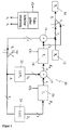
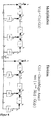
- FIG. 1 is considered, from the explanation of which then also the understanding of the circuit according to Figure 2 results by itself.
- S 2 , S 1 are switches for K signal lines with switch positions 1 and 2.
- T i One-cycle delay for K signal lines.
- the input data block [X] is contained completely or element by element in a register 12, at the output of which a value X i is present.
- the first five elements of the fail-safe data block [Y] consist of the elements of the input data block [X].
- Two parity words should now be added to the saved data block [Y].
- the individual values X i are given to the output at each division step via a switch S 1 in the "1" position, from which the error-protected data words are taken, shown here as an example as register 14.
- modulo 2 addition ( ⁇ ) by the exclusive-or elements corresponds to the following truth table (Table 3): X 1 X 2 Y 0 0 0 0 1 1 1 0 1 1 1 0
- the circuit according to FIG. 1 also contains two table memories 22 and 24, here additionally designated LUT 2 and LUT 1 , derived from the term look-up table.
- the number of memory locations in these table memories is 8 (2 K ).
- These table memories can be implemented either by commercially available electronic read-only memory modules or by programmable logic cells (PLD). Addresses A i (at the respective clock) are applied to the address inputs and, depending on the address that is created, a data word D i stored under this address is read out.
- each table memory contains for all possible values 0.1, ⁇ , ⁇ 2 .... the product result, which is obtained by multiplying the input value by the relevant coefficient of the generator polynomial. In the present case, the possible input values for the data value D 2 are multiplied by ⁇ 3 , for the data value D 1 by ⁇ .
- the ⁇ i as K-bit words can be found in the GF (2 K ) (see Table 1).
- the two switches S 1 and S 2 are initially in the "1" position.
- polynomial division steps are performed on each clock, and also the elements of [X] are given on the output for Y during the first five clocks.
- the intermediate results obtained depend on the existing data of the currently current clock and the data of the previous clock.
- the clock is generated by a clock generator in the form of a clock signal CL.
- the delay elements 18 and 20 shown in FIG. 1 each generate a delay by one clock, as can be seen from Table 2 above.
- the individual words of the input data block are transferred to the saved data block (output data block) in the first five cycles.
- the switches S 1 and S 2 are brought into the "2" position. Now the two parity words P 1 and P 2 at the output of the delay element 18 can be removed and added to the output data block.
- the switches are switched by a switch controller depending on the number of words within an input data block that is to be assumed to be known.
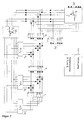
- Figure 2 shows a circuit for any values of 2e.
- the modulo 2 adders are bitwise shown for each of the K bits.
- the circuit can be set to one expand any number of bits, it can also be extended to any number Extend the value of 2e.
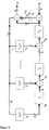
- Figure 3 shows a slightly compared to the circuit of Figure 2 modified embodiment, but on the individual representations of the individual bit lines was dispensed with.
- this circuit manages with only one switch S 1 .
- the data words are clocked into the register for the output data word Y via the two EXCLUSIVE-OR gates 17 and 16, while the switch S 1 is in the "1" position.
- the work processes in the remaining circuit correspond to the process explained above.
- the switch S 1 is set to the "2" position so that the parity words are added to the output data word Y.
- circuit shown in Figure 3 can also be carried out a modified method for the formation of parity words used as outlined below.
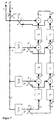
- FIG 4 a circuit is shown, which first determines the divisor C (z) by division and then the output polynomial Y (z) by multiplication, the division in the delay elements T 1 to T 2e and the multiplication in the Delay elements T 2e + 1 to T 4e is performed. Switch S 1 is moved from position 1 to position 2 immediately after the mth cycle at which the division has ended. Overall, m + 2e clocks are required to form the output polynomial Y (z).
- LUT Tables 4 and 5 can be used for this example.
- Switch S 1 is to be moved from position 1 to position 2 immediately after the nth cycle. To illustrate the sequence, the circuit parts are shown separately in FIG. 8.
- P (z) e.g. 2 e - X (z) - H (z)
- the circuit design of the method is shown in FIG. 6.
- the switches S 0 and S m-2e are in position 1 at the beginning of the operation.
- the multiplication of the input polynomial X (z) by the inverse polynomial H (z) according to step (1) is carried out using the tables LUT 1 to LUT m -2e and the K-fold one-stroke delay elements T 1 to T m-2e .
- step (1) is divided by the polynomial z m + 1 and the remainder is determined by switching the switches S 0 and S m-2e to position 2 immediately after the m-2 th clock.
- Division of the remainder Step (2) through the inverse polynomial H (z) takes place with the aid of the K-fold one-cycle delay elements T m-2e + 1 to T 2m-4e .
- the parity words [P] corresponding to the division words are appended directly to the information words [X].
- the advantage of the circuit is that only m-2e LUT tables be used, which is large with a number of 2e parity words compared to the number (m-2e) of information words in a block, leads to a reduction in circuitry.
- the inverse polynomial results in H (z) (z m + 1)
- G (z) z 3 + ⁇ 2 z 2 + z + ⁇ .
- the structure of the LUT tables for this example is as follows:
- the ⁇ i can be found as K-bit words from GF (2 K ).
- [X] [ ⁇ 5 ⁇ 2 ⁇ ]
- the inverse polynomial H (z) z 3 + ⁇ 2 z 2 + z + ⁇
- M 5 to M 10 represent the coefficients of the result polynomial after the multiplication step (1).
Landscapes
- Physics & Mathematics (AREA)
- Algebra (AREA)
- General Physics & Mathematics (AREA)
- Mathematical Physics (AREA)
- Pure & Applied Mathematics (AREA)
- Probability & Statistics with Applications (AREA)
- Engineering & Computer Science (AREA)
- Theoretical Computer Science (AREA)
- Error Detection And Correction (AREA)
- Detection And Correction Of Errors (AREA)
- Detection And Prevention Of Errors In Transmission (AREA)
- Signal Processing For Digital Recording And Reproducing (AREA)
Claims (3)
- Méthode pour générer des blocs de données protégés contre les erreurs par génération de 2e mots de parité associés respectivement à un bloc de données d'entrée [X], e représentant le nombre des erreurs à corriger par bloc, pour un code de bloc réduit ou non réduit, systématique, cyclique et de valeur 2K, dont les éléments sont des éléments de GF(2K) et dont le polynôme générateur G(z) est basé sur 2e zéros de GF(2K), caractérisée par les phases suivantes :a) Formation du polynôme générateur G(z) ;b) Formation d'un polynôme inverse H(z) par division du polynôme zm + 1 par le polynôme générateur G(z) ;c) Elargissement du bloc par déplacement du bloc d'entrée [X] = [Xi Xi-1 ... X2 X1] de 2e emplacements de mots pour libérer de la place pour les 2e mots de parité [P2e P2e-1 ... P2 P1], de sorte que le bloc de sortie a la forme [Y] = [Xi Xi-2 ... X2 X1 P2e P2e-1 ... P2 P1];d) Multiplication du polynôme d'entrée déplacé X(z), associé au bloc d'entrée [X], par le polynôme inverse H(z) suivant les règles de calcul de GF(2K);e) Division du résultat de la phase d) par le polynôme zm + 1 suivant les règles de calcul de GF(2K) et détermination du reste de cette division ;f) Division du reste de la phase e) par le polynôme inverse H(z) et détermination des mots diviseurs [C2e C2e-1 ... C2 C1] suivant les règles de calcul de GF(2K) etg) Obtention des mots de parité [P] = [P2e P2e-1 ... P2 P1] à partir des mots diviseurs obtenus dans la phase f) par l'identité [P] = [C2e C2e-1 ... C2 C1].
- Méthode suivant la revendication 1, caractérisée en ce que le polynôme générateur est formé par la multiplication, définie dans GF(2K), d'au total 2e expressions différentes, chaque expression résultant de l'addition, définie dans GF(2K), de l'opérateur de déplacement z et de l'un des éléments possibles différents de zéro de GF(2K).
- Méthode suivant la revendication 2, caractérisée en ce que le nombre i des mots dans un bloc d'entrée [X] = [Xi Xi-1 ... X2 X1] est i = 24 ou i = 28, le nombre 2e des mots de parité [P2e P2e-1 ... P2 P1] est 2e = 4, le polynôme générateur G(z) = (z+α0)(z+α1)(z+α2)(z+α3) = z4 + α75z3 + α249z2 + α78z + α6, et le champ de Galois à la base des opérations et des éléments est GF(2K) avec K = 8, αj étant une racine du polynôme générateur.
Priority Applications (5)
| Application Number | Priority Date | Filing Date | Title |
|---|---|---|---|
| DE59800859T DE59800859D1 (de) | 1998-10-20 | 1998-10-20 | Verfahren und Anordnung zum Erzeugen von fehlergesicherten Datenblöcken durch Erzeugen von Paritätsworten und Datenträger mit gemäss dem Verfahren erzeugten Datenblöcken |
| AT98119880T ATE202244T1 (de) | 1998-10-20 | 1998-10-20 | Verfahren und anordnung zum erzeugen von fehlergesicherten datenblöcken durch erzeugen von paritätsworten und datenträger mit gemäss dem verfahren erzeugten datenblöcken |
| EP98119880A EP0996231B1 (fr) | 1998-10-20 | 1998-10-20 | Méthode et dispositif pour générer des blocs de données protégées contre des erreurs ainsi que support de données comprenant des blocs de données générées selon la méthode |
| PCT/EP1999/007570 WO2000024130A1 (fr) | 1998-10-20 | 1999-10-08 | Procede et dispositif pour produire des blocs de donnees proteges contre les erreurs par production de mots de parite, et support de donnees comportant des blocs de donnees produits selon ledit procede |
| AU63367/99A AU6336799A (en) | 1998-10-20 | 1999-10-08 | Method and device for producing data blocks which are error-protected through production of parity words, and data medium comprising data blocks produced according to said method |
Applications Claiming Priority (1)
| Application Number | Priority Date | Filing Date | Title |
|---|---|---|---|
| EP98119880A EP0996231B1 (fr) | 1998-10-20 | 1998-10-20 | Méthode et dispositif pour générer des blocs de données protégées contre des erreurs ainsi que support de données comprenant des blocs de données générées selon la méthode |
Publications (2)
| Publication Number | Publication Date |
|---|---|
| EP0996231A1 EP0996231A1 (fr) | 2000-04-26 |
| EP0996231B1 true EP0996231B1 (fr) | 2001-06-13 |
Family
ID=8232827
Family Applications (1)
| Application Number | Title | Priority Date | Filing Date |
|---|---|---|---|
| EP98119880A Expired - Lifetime EP0996231B1 (fr) | 1998-10-20 | 1998-10-20 | Méthode et dispositif pour générer des blocs de données protégées contre des erreurs ainsi que support de données comprenant des blocs de données générées selon la méthode |
Country Status (5)
| Country | Link |
|---|---|
| EP (1) | EP0996231B1 (fr) |
| AT (1) | ATE202244T1 (fr) |
| AU (1) | AU6336799A (fr) |
| DE (1) | DE59800859D1 (fr) |
| WO (1) | WO2000024130A1 (fr) |
Family Cites Families (6)
| Publication number | Priority date | Publication date | Assignee | Title |
|---|---|---|---|---|
| JPS574629A (en) * | 1980-05-21 | 1982-01-11 | Sony Corp | Data transmitting method capable of correction of error |
| JPS62180617A (ja) * | 1986-02-04 | 1987-08-07 | Victor Co Of Japan Ltd | パリテイ生成回路 |
| US5040179A (en) * | 1989-08-18 | 1991-08-13 | Loral Aerospace Corp. | High data rate BCH encoder |
| US5140596A (en) * | 1990-02-20 | 1992-08-18 | Eastman Kodak Company | High speed encoder for non-systematic codes |
| US5285455A (en) * | 1992-02-03 | 1994-02-08 | Lsi Logic Corporation | Serial data encoder |
| EP0584864B1 (fr) * | 1992-08-21 | 1997-11-05 | Koninklijke Philips Electronics N.V. | Procédé sobre en hardware et dispositif pour le codage de codes BCH et notamment de codes Reed-Solomon |
-
1998
- 1998-10-20 DE DE59800859T patent/DE59800859D1/de not_active Expired - Fee Related
- 1998-10-20 AT AT98119880T patent/ATE202244T1/de not_active IP Right Cessation
- 1998-10-20 EP EP98119880A patent/EP0996231B1/fr not_active Expired - Lifetime
-
1999
- 1999-10-08 AU AU63367/99A patent/AU6336799A/en not_active Abandoned
- 1999-10-08 WO PCT/EP1999/007570 patent/WO2000024130A1/fr not_active Ceased
Also Published As
| Publication number | Publication date |
|---|---|
| ATE202244T1 (de) | 2001-06-15 |
| AU6336799A (en) | 2000-05-08 |
| WO2000024130A1 (fr) | 2000-04-27 |
| DE59800859D1 (de) | 2001-07-19 |
| EP0996231A1 (fr) | 2000-04-26 |
Similar Documents
| Publication | Publication Date | Title |
|---|---|---|
| DE69424877T2 (de) | Reed-solomon-dekoder | |
| DE2916710C2 (fr) | ||
| DE69320321T2 (de) | Verfahren und Gerät zum Nachprüfen von CRC-Koden, wobei CRC Teilkode kombiniert werden | |
| DE3852423T2 (de) | Kodierverfahren und Kodierer mit Reed-Solomon Fehlerkorrekturcode. | |
| DE2106314B2 (de) | Anordnung zur Fehlererkennung und -korrektur in einem aus b Bits bestehenden Byte eines K Datenbytes enthaltenden Datenblocks | |
| DE3882223T2 (de) | Ausgebreitete Fehlerkorrekturvorrichtung mit Einzel-Paket-Fehlerkorrektur und Doppel-Paket-Fehlerdetektionscoden. | |
| DE2159108A1 (de) | Anordnung zur Erzeugung zyklischer Redundanzprüfzeichen | |
| DE2834963A1 (de) | Verfahren und einrichtung zur fehlerkorrektur von uebertragenen daten | |
| DE69907566T2 (de) | Reed Solomon Kodierungsgerät und Reed Solomon Kodierungsverfahren | |
| EP0545498B1 (fr) | Procédé et circuit pour décoder des signaux codés en RS | |
| DE102012208711B4 (de) | Vorrichtung zum Erzeugen einer Prüfsumme | |
| DE3750526T2 (de) | Dekodierer. | |
| DE4220196C2 (de) | Halbleiterspeichervorrichtung und Verfahren zum Korrigieren eines Datenfehlers in einer Halbleiterspeichervorrichtung entsprechend einer vorbestimmten Hamming-Matrix | |
| DE4105860C2 (de) | Schaltungsanordnung zum Erkennen und Korrigieren von Fehlern in Datenworten | |
| DE69732076T2 (de) | Reed-Solomon Dekodierer mit universeller Prozessoreinheit und speziellen Schaltungen | |
| DE2217935A1 (de) | Anordnung und Verfahren zur Korrektur von Doppelfehlern | |
| DE102020110787B3 (de) | Schaltung und verfahren zum kodieren oder dekodieren eines datenworts | |
| DE3789266T2 (de) | Fehlerkorrekturgerät. | |
| DE4117726C2 (de) | Fehlerkorrekturverfahren und Einrichtung zu dessen Durchführung | |
| DE102006005817B4 (de) | Fehlererkennungsvorrichtung für einen Adressdecoder und Vorrichtung zur Fehlererkennung für einen Adressdecoder | |
| DE3702697C2 (fr) | ||
| EP0996231B1 (fr) | Méthode et dispositif pour générer des blocs de données protégées contre des erreurs ainsi que support de données comprenant des blocs de données générées selon la méthode | |
| DE3104762C2 (fr) | ||
| DE69026363T2 (de) | Multipositionsverschieber mit Paritätsbitgenerator | |
| DE4333382A1 (de) | Verfahren und Vorrichtung zum Bilden des Reziproken eines beliebigen Elementes in einem finiten Feld |
Legal Events
| Date | Code | Title | Description |
|---|---|---|---|
| PUAI | Public reference made under article 153(3) epc to a published international application that has entered the european phase |
Free format text: ORIGINAL CODE: 0009012 |
|
| 17P | Request for examination filed |
Effective date: 19981020 |
|
| AK | Designated contracting states |
Kind code of ref document: A1 Designated state(s): AT BE CH CY DE DK ES FI FR GB GR IE IT LI LU MC NL PT SE |
|
| AX | Request for extension of the european patent |
Free format text: AL;LT;LV;MK;RO;SI |
|
| GRAG | Despatch of communication of intention to grant |
Free format text: ORIGINAL CODE: EPIDOS AGRA |
|
| GRAG | Despatch of communication of intention to grant |
Free format text: ORIGINAL CODE: EPIDOS AGRA |
|
| GRAH | Despatch of communication of intention to grant a patent |
Free format text: ORIGINAL CODE: EPIDOS IGRA |
|
| AKX | Designation fees paid |
Free format text: AT BE CH CY DE DK ES FI FR GB GR IE IT LI LU MC NL PT SE |
|
| AXX | Extension fees paid |
Free format text: AL PAYMENT 20001010;LT PAYMENT 20001010;LV PAYMENT 20001010;MK PAYMENT 20001010;RO PAYMENT 20001010;SI PAYMENT 20001010 |
|
| GRAH | Despatch of communication of intention to grant a patent |
Free format text: ORIGINAL CODE: EPIDOS IGRA |
|
| GRAA | (expected) grant |
Free format text: ORIGINAL CODE: 0009210 |
|
| AK | Designated contracting states |
Kind code of ref document: B1 Designated state(s): AT BE CH CY DE DK ES FI FR GB GR IE IT LI LU MC NL PT SE |
|
| AX | Request for extension of the european patent |
Free format text: AL PAYMENT 20001010;LT PAYMENT 20001010;LV PAYMENT 20001010;MK PAYMENT 20001010;RO PAYMENT 20001010;SI PAYMENT 20001010 |
|
| LTIE | Lt: invalidation of european patent or patent extension | ||
| PG25 | Lapsed in a contracting state [announced via postgrant information from national office to epo] |
Ref country code: NL Free format text: LAPSE BECAUSE OF FAILURE TO SUBMIT A TRANSLATION OF THE DESCRIPTION OR TO PAY THE FEE WITHIN THE PRESCRIBED TIME-LIMIT Effective date: 20010613 Ref country code: IT Free format text: LAPSE BECAUSE OF FAILURE TO SUBMIT A TRANSLATION OF THE DESCRIPTION OR TO PAY THE FEE WITHIN THE PRESCRIBED TIME-LIMIT;WARNING: LAPSES OF ITALIAN PATENTS WITH EFFECTIVE DATE BEFORE 2007 MAY HAVE OCCURRED AT ANY TIME BEFORE 2007. THE CORRECT EFFECTIVE DATE MAY BE DIFFERENT FROM THE ONE RECORDED. Effective date: 20010613 Ref country code: IE Free format text: LAPSE BECAUSE OF FAILURE TO SUBMIT A TRANSLATION OF THE DESCRIPTION OR TO PAY THE FEE WITHIN THE PRESCRIBED TIME-LIMIT Effective date: 20010613 Ref country code: GB Free format text: LAPSE BECAUSE OF FAILURE TO SUBMIT A TRANSLATION OF THE DESCRIPTION OR TO PAY THE FEE WITHIN THE PRESCRIBED TIME-LIMIT Effective date: 20010613 Ref country code: FR Free format text: LAPSE BECAUSE OF FAILURE TO SUBMIT A TRANSLATION OF THE DESCRIPTION OR TO PAY THE FEE WITHIN THE PRESCRIBED TIME-LIMIT Effective date: 20010613 Ref country code: FI Free format text: LAPSE BECAUSE OF FAILURE TO SUBMIT A TRANSLATION OF THE DESCRIPTION OR TO PAY THE FEE WITHIN THE PRESCRIBED TIME-LIMIT Effective date: 20010613 Ref country code: CY Free format text: LAPSE BECAUSE OF NON-PAYMENT OF DUE FEES Effective date: 20010613 |
|
| REF | Corresponds to: |
Ref document number: 202244 Country of ref document: AT Date of ref document: 20010615 Kind code of ref document: T |
|
| REF | Corresponds to: |
Ref document number: 59800859 Country of ref document: DE Date of ref document: 20010719 |
|
| REG | Reference to a national code |
Ref country code: IE Ref legal event code: FG4D Free format text: GERMAN |
|
| PG25 | Lapsed in a contracting state [announced via postgrant information from national office to epo] |
Ref country code: SE Free format text: LAPSE BECAUSE OF FAILURE TO SUBMIT A TRANSLATION OF THE DESCRIPTION OR TO PAY THE FEE WITHIN THE PRESCRIBED TIME-LIMIT Effective date: 20010913 Ref country code: DK Free format text: LAPSE BECAUSE OF FAILURE TO SUBMIT A TRANSLATION OF THE DESCRIPTION OR TO PAY THE FEE WITHIN THE PRESCRIBED TIME-LIMIT Effective date: 20010913 |
|
| PG25 | Lapsed in a contracting state [announced via postgrant information from national office to epo] |
Ref country code: GR Free format text: LAPSE BECAUSE OF FAILURE TO SUBMIT A TRANSLATION OF THE DESCRIPTION OR TO PAY THE FEE WITHIN THE PRESCRIBED TIME-LIMIT Effective date: 20010914 |
|
| PG25 | Lapsed in a contracting state [announced via postgrant information from national office to epo] |
Ref country code: PT Free format text: LAPSE BECAUSE OF FAILURE TO SUBMIT A TRANSLATION OF THE DESCRIPTION OR TO PAY THE FEE WITHIN THE PRESCRIBED TIME-LIMIT Effective date: 20010917 |
|
| PG25 | Lapsed in a contracting state [announced via postgrant information from national office to epo] |
Ref country code: MC Free format text: LAPSE BECAUSE OF NON-PAYMENT OF DUE FEES Effective date: 20011020 Ref country code: LU Free format text: LAPSE BECAUSE OF NON-PAYMENT OF DUE FEES Effective date: 20011020 Ref country code: AT Free format text: LAPSE BECAUSE OF NON-PAYMENT OF DUE FEES Effective date: 20011020 |
|
| PG25 | Lapsed in a contracting state [announced via postgrant information from national office to epo] |
Ref country code: BE Free format text: LAPSE BECAUSE OF NON-PAYMENT OF DUE FEES Effective date: 20011031 |
|
| NLV1 | Nl: lapsed or annulled due to failure to fulfill the requirements of art. 29p and 29m of the patents act | ||
| GBV | Gb: ep patent (uk) treated as always having been void in accordance with gb section 77(7)/1977 [no translation filed] |
Effective date: 20010613 |
|
| PG25 | Lapsed in a contracting state [announced via postgrant information from national office to epo] |
Ref country code: ES Free format text: LAPSE BECAUSE OF FAILURE TO SUBMIT A TRANSLATION OF THE DESCRIPTION OR TO PAY THE FEE WITHIN THE PRESCRIBED TIME-LIMIT Effective date: 20011220 |
|
| EN | Fr: translation not filed | ||
| PLBE | No opposition filed within time limit |
Free format text: ORIGINAL CODE: 0009261 |
|
| STAA | Information on the status of an ep patent application or granted ep patent |
Free format text: STATUS: NO OPPOSITION FILED WITHIN TIME LIMIT |
|
| BERE | Be: lapsed |
Owner name: DIG MICROCODE G.M.B.H. Effective date: 20011031 |
|
| 26N | No opposition filed | ||
| PG25 | Lapsed in a contracting state [announced via postgrant information from national office to epo] |
Ref country code: DE Free format text: LAPSE BECAUSE OF NON-PAYMENT OF DUE FEES Effective date: 20020702 |
|
| PG25 | Lapsed in a contracting state [announced via postgrant information from national office to epo] |
Ref country code: LI Free format text: LAPSE BECAUSE OF NON-PAYMENT OF DUE FEES Effective date: 20021031 Ref country code: CH Free format text: LAPSE BECAUSE OF NON-PAYMENT OF DUE FEES Effective date: 20021031 |
|
| REG | Reference to a national code |
Ref country code: CH Ref legal event code: PL |