EP0996236A1 - Procédé et appareil de compensation de la distorsion dans un system de communication à access multiples - Google Patents
Procédé et appareil de compensation de la distorsion dans un system de communication à access multiples Download PDFInfo
- Publication number
- EP0996236A1 EP0996236A1 EP98402644A EP98402644A EP0996236A1 EP 0996236 A1 EP0996236 A1 EP 0996236A1 EP 98402644 A EP98402644 A EP 98402644A EP 98402644 A EP98402644 A EP 98402644A EP 0996236 A1 EP0996236 A1 EP 0996236A1
- Authority
- EP
- European Patent Office
- Prior art keywords
- user network
- central station
- network terminal
- distortions
- communication channel
- Prior art date
- Legal status (The legal status is an assumption and is not a legal conclusion. Google has not performed a legal analysis and makes no representation as to the accuracy of the status listed.)
- Withdrawn
Links
- 238000004891 communication Methods 0.000 title claims abstract description 77
- 238000000034 method Methods 0.000 title claims abstract description 26
- 230000001419 dependent effect Effects 0.000 claims abstract description 22
- 238000012937 correction Methods 0.000 claims description 36
- 238000012360 testing method Methods 0.000 claims description 25
- 238000000605 extraction Methods 0.000 claims description 22
- 230000001360 synchronised effect Effects 0.000 claims 2
- 108091006146 Channels Proteins 0.000 description 32
- 230000005540 biological transmission Effects 0.000 description 4
- 239000000835 fiber Substances 0.000 description 3
- 210000001550 testis Anatomy 0.000 description 3
- 230000003287 optical effect Effects 0.000 description 2
- 238000011144 upstream manufacturing Methods 0.000 description 2
- 230000003044 adaptive effect Effects 0.000 description 1
- 230000006735 deficit Effects 0.000 description 1
- 238000001914 filtration Methods 0.000 description 1
- 238000012549 training Methods 0.000 description 1
Images


Classifications
-
- H—ELECTRICITY
- H04—ELECTRIC COMMUNICATION TECHNIQUE
- H04J—MULTIPLEX COMMUNICATION
- H04J3/00—Time-division multiplex systems
- H04J3/02—Details
- H04J3/06—Synchronising arrangements
- H04J3/0635—Clock or time synchronisation in a network
- H04J3/0682—Clock or time synchronisation in a network by delay compensation, e.g. by compensation of propagation delay or variations thereof, by ranging
-
- H—ELECTRICITY
- H04—ELECTRIC COMMUNICATION TECHNIQUE
- H04B—TRANSMISSION
- H04B3/00—Line transmission systems
- H04B3/02—Details
- H04B3/04—Control of transmission; Equalising
Definitions
- the present invention relates to a method to compensate for distortions in a communications network, as is described in the preamble of claim 1, to a user network terminal to be used in such a communications network and adapted to perform such a method, as is described in the preamble of claim 6, to a central station of such a communications network as is described in the preamble of claim 11 and to a such a communications network as is described in the preamble of claim 17.
- Hybrid Fiber Coax hereafter abbreviated with HFC, network is described, including a head-end corresponding to the central station of the non-characteristic part of claims 1,6,11 and 17, and which is coupled by a common link consisting of an optical and a coaxial part, and respective individual links or drops, to a plurality of user network terminals such as set top boxes and cable modems, respectively abbreviated with STB and CDM in Figure 1 of the referred prior art document.
- the head-end of the described prior art communications system includes an adaptive equaliser corresponding to the equalisation device as described in the preamble of claims 11 and 17, in order to compensate for fast varying distortions such as ingress and impulse noise.
- each of the communication channels themselves introduces an additional distortion.
- This channel induced distortion is different for each user network terminal since each communication channel is different, because of the difference in length, diameter, number of inserted amplifiers etc., of each of these communication channels coupled between each user network terminal and the central station.
- system architecture by describing that amplitude and phase characteristic differences between subscribers are to be compensated, without however explicitly offering a solution to this problem.
- An object of the present invention is therefore to provide a method, a user network terminal, a central station and a communications network of the above known type wherein the problem of distortion compensation in general is solved.
- this object is achieved due to the fact that distortions which are particular to one respective communication channel coupled to a respective user network terminal, are compensated for in this respective user network terminal itself as is described in the characteristic part of claim 1, this particular user network terminal itself therefore including a pre-correction means, as is further described in the characteristic parts of claims 6 and 17, and that said central station only equalises distortions which are common to all communication channels, as is described in the characteristic part of claim 11.
- the transmission of the test signal by the user network terminals, and the subsequent determination of the correction parameters by the central station is performed once, for instance during initialisation of the user network terminal, or at predetermined instances.
- a synchronisation at symbol level results in timing-error-free data signals transmitted by this user network terminal to the central station.
- the necessary correction parameter for performing this timing or symbol synchronisation being a clock information signal
- the timing correction is performed within a timing control means of the pre-correction means, as is stated in claim 8, based on the clock information signal extracted from the test signal and returned back to the pre-correction means.
- a further characteristic feature of the present invention is that these distortions which are only dependent on one particular communication channel include frequency errors, which are compensated for by a frequency synchronisation operation between the respective user network terminal coupled to this particular communication channel and the central station, as is further described in claims 4, 9 and 14.
- a synchronisation operation at the frequency level results in frequency error-free data signals to be transmitted from the user network terminal to the central station.
- Frequency errors are in general related to the carrier with which the data signal is to be modulated.
- a carrier extraction means is included in this central station for extraction of this carrier information from a test signal transmitted by the user network terminal.
- This carrier information is consecutively retransmitted as a feedback signal to the user network terminal in which a frequency control means is adapted to synchronise all subsequent data signals at the frequency level using the correct carrier information.
- This operation may for instance consist of modulating the data signal with a carrier wave, the frequency of which was provided by the central station.
- these distortions which are only dependent on one particular communication channel include amplitude and phase errors, to be compensated for by an equalisation operation within the respective user network terminal coupled to this particular communication channel as is further described in claims 5 and 10, and whereby information necessary for performing this equalisation operation is extracted within the central station and provided by this central station to this respective user network terminal, as is further described in claim 15.
- the particular filter characteristic features of the communications channel itself such as amplitude and phase characteristics, are compensated within the user network terminal by filtering the data signals to be transmitted by the user network terminal, the resultant operation thus being an equalisation of these amplitude and phase errors.
- the filter or equaliser coefficients are thereby provided by the central station, again by extracting the necessary information from a test signal transmitted by the respective user network terminal, and by providing these coefficients back to the respective user network terminal, as stated in claim 5,10 and 15.
- the present invention also relates to a communication network including a plurality of user network terminals and including a central station, at least one user network terminal and said central station being adapted to perform the above described method, as is described in claim 17.
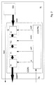
- a central station CS is coupled to each of a plurality of user network terminals T1,.., Ti,..Tn, via a common link L and a respective corresponding individual link denoted L1,...,Li,...,Ln.
- This communications network thus corresponds to a multiple access communications network with point to multipoint architecture in the downstream direction from central station to the user network terminals and with a multipoint to point architecture in the upstream direction from the user network terminals to the central station.
- Each user network terminal for instance terminal Ti, is thus connected to the central station via a unique communication channel Ci, consisting of the cascade connection of the common link L and the corresponding individual link, being Li for terminal Ti .
- Such communications networks can for instance consist of hybrid fiber coax, abbreviated with HFC, networks, or asynchronous passive optical, abbreviated with APON, networks, multi-user twisted pair networks and fixed point wireless networks.
- the individual network links or drops can significantly differ from each other in length, diameter, the number of inserted amplifiers, etc. Therefore the corresponding communication channels C1,...,Ci,..., Cn all have different characteristics, introducing a different delay, frequency shift, and amplitude and phase error with respect to identical test signals transmitted by each of the terminals T1 to Tn.
- this kind of channel inherent distortions hardly vary in function of the time.
- another type of distortions for instance consisting of impulse or ingress noise in HFC networks are present, as was already described in the prior art article referred to in the introductory part of this document.
- This kind of noise is highly variable as a function of the time, as was also shown in this prior art article. Yet this noise, seen from the central station, can be considered as terminal or channel independent. Summarised two types of distortions are present in such communications networks : on one hand the slowly varying, but communication channel dependent errors, on the other hand fast varying, but common channel characteristic noise errors.
- the first category of distortions namely channel dependent distortions, are, according to the present invention, compensated for within the individual user network terminals to which these communication channels are coupled.
- distortions related to communication channel Ci physically consisting of common link L and drop Li, are compensated in user network terminal Ti.
- signals generated within a signal source denoted SSi on Fig. 1 are pre-corrected by means of a pre-correction means CORi, before being transmitted towards the central station CS.
- SSi signal source
- CORi pre-correction means
- the pre-correction device CORi thereby consists of four main building blocks : a terminal equalisation means Ei, which itself is split into a filter Ai and an amplifier Pi, a timing control means TCi, a frequency control means Fi and a control device CONTRi.
- a terminal equalisation means Ei which itself is split into a filter Ai and an amplifier Pi
- TCi timing control means
- Fi frequency control means
- CONTRi control device CONTRi.
- the data generated by the signal source SSi and which are denoted datai
- a timing synchronisation operation is performed on the filtered data, the result of this operation being followed by a frequency synchronisation step, the result of which is finally amplified within a power control or amplifier device.
- the result of the complete correction operation being denoted as dataRFi.
- control device denoted CONTRi on Fig. 2.
- this control device thereby provides the filter coefficients, denoted coefi, to the programmable filter Ai, a clock information signal denoted clocki, to the timing control means TCi, a carrier information signal, denoted carfi, to the frequency control means Fi, and power information, denoted pi, to the power amplifier Pi.
- These control parameters are, in one variant of the method and embodiment of central station and user network terminal, either determined within the control device CONTRi itself. In another variant of the method and embodiment of the central station and user network terminal, these parameters are determined centrally within the central station CS.
- the signal source SSi of the user network terminal Ti transmits a test signal towards the central station CS.
- the latter receives this and merely transmits it back as a feedback signal.
- the control device which includes the necessary comparison and extraction devices in order to derive from the original test signal and from the re-transmitted test signal, the carrier information signal, the clock information signal and filter and power coefficients for subsequently providing this to the timing control means, frequency control means, programmable filter and power amplifier respectively.
- This solution may be used in case only a few user network terminals are part of the network since it is clear that in this case each control device of each user network terminal needs to incorporate the necessary comparing and extraction devices for extracting the correction parameters.
- This solution is used in the embodiment of the user network terminal depicted in Fig. 2, and of the central station depicted in Fig. 3.
- the user terminal signal source SSi thereby transmits a test signal, denoted testi , towards the central station CS.
- This central station CS includes a receive filter, denoted P*(f) which receives this test signal testi, thereon performs a filter operation, the resultant signal being tesfi.
- receive filters are commonly known by a person skilled in the art, and since these are not relevant to this invention, these will not be further described into detail in this document.
- the filtered test signal testfi is further transmitted towards a extraction means EXT included in the central station.
- This extraction means itself includes a clock extraction means, denoted TEXT, adapted to extract from the incoming filtered test signal testfi a clock information signal denoted clocki.
- TEXT further includes a carrier extraction means, denoted FEXT, adapted to extract from testfi a carrier information signal, denoted carfi, as well as a channel parameter extraction means denoted CHANP, adapted to extract from testfi channel modelling parameters, denoted coefi and Pi, and respectively related to the phase and amplitude errors.
- the three sets of information signals are combined within a combining device, denoted COM, of the extraction means EXT, to form a feedback signal denoted fbi, which is finally transmitted back towards the control device CONTRi of the pre-correction means CORi of the user network terminal Ti.
- the control device CONTRi is thus adapted to derive from the received feedback signal fbi, the individual correction parameters and to provide them to the appropriate previously described functional blocks within the pre-correction means.
- timing control means TCi may consist of an interpolator for performing the timing compensation.
- the frequency control means may consist of a complex mixer including a digital voltage controlled oscillator, for performing the frequency correction.
- the terminal equalisation means consists, as already mentioned in a previous paragraph of this document of a programmable filter together with a power amplifier.
- the transmission of the test signal testi by the user network terminal Ti are generally performed during start-up of the system, or start up of a particular terminal. In other variants of the method, this operation can be repeated at predetermined instances.
- the necessary correction parameters to be used in the pre-correction means are determined and transmitted to the control device of this pre-correction means, they are stored within this control device, and subsequently used for pre-correcting all data signals to be transmitted by the user network terminal. In this way, the transmitted signal dataRFi is thus compensated for channel-inherent distortions.
- the pre-corrected signal dataRFi is received by the central station CS, it is first filtered by the receive filter P*(f), as can be seen from Fig. 3, for thereby generating a filtered signal dataRFFI, of which the common noise is subsequently eliminated within the equalisation device ED.
Landscapes
- Engineering & Computer Science (AREA)
- Computer Networks & Wireless Communication (AREA)
- Signal Processing (AREA)
- Small-Scale Networks (AREA)
- Cable Transmission Systems, Equalization Of Radio And Reduction Of Echo (AREA)
- Maintenance And Management Of Digital Transmission (AREA)
- Synchronisation In Digital Transmission Systems (AREA)
Priority Applications (4)
| Application Number | Priority Date | Filing Date | Title |
|---|---|---|---|
| EP98402644A EP0996236A1 (fr) | 1998-10-23 | 1998-10-23 | Procédé et appareil de compensation de la distorsion dans un system de communication à access multiples |
| CA002284398A CA2284398A1 (fr) | 1998-10-23 | 1999-09-29 | Methode de compensation de distorsion dans un systeme de communications a acces multiple, et station terminale et station centrale faisant partie d'un tel systeme de communications pour l'application de cette methode |
| JP11289128A JP2000196649A (ja) | 1998-10-23 | 1999-10-12 | 多重アクセス通信システム内で歪みを補償する方法、およびそのような方法を行うそのような通信システム中に含まれる端末局と中央局 |
| AU56033/99A AU5603399A (en) | 1998-10-23 | 1999-10-22 | Method to compensate for distortions within a multiple access communications system, and terminal station and central station included in such a communications system for performing such a method |
Applications Claiming Priority (1)
| Application Number | Priority Date | Filing Date | Title |
|---|---|---|---|
| EP98402644A EP0996236A1 (fr) | 1998-10-23 | 1998-10-23 | Procédé et appareil de compensation de la distorsion dans un system de communication à access multiples |
Publications (1)
| Publication Number | Publication Date |
|---|---|
| EP0996236A1 true EP0996236A1 (fr) | 2000-04-26 |
Family
ID=8235538
Family Applications (1)
| Application Number | Title | Priority Date | Filing Date |
|---|---|---|---|
| EP98402644A Withdrawn EP0996236A1 (fr) | 1998-10-23 | 1998-10-23 | Procédé et appareil de compensation de la distorsion dans un system de communication à access multiples |
Country Status (4)
| Country | Link |
|---|---|
| EP (1) | EP0996236A1 (fr) |
| JP (1) | JP2000196649A (fr) |
| AU (1) | AU5603399A (fr) |
| CA (1) | CA2284398A1 (fr) |
Citations (4)
| Publication number | Priority date | Publication date | Assignee | Title |
|---|---|---|---|---|
| EP0334569A2 (fr) * | 1988-03-21 | 1989-09-27 | First Pacific Networks, Inc. | Procédé et système pour la transmission d'information |
| EP0624011A1 (fr) * | 1993-04-27 | 1994-11-09 | ALCATEL BELL Naamloze Vennootschap | Dispositif pour la compensation de dispersion |
| EP0768779A2 (fr) * | 1995-10-10 | 1997-04-16 | Motorola, Inc. | Suppression de distorsions et d'interference dans des systèmes de communication à acces multiple |
| GB2312362A (en) * | 1996-04-20 | 1997-10-22 | Northern Telecom Ltd | Channel equalisation in telecomms system |
-
1998
- 1998-10-23 EP EP98402644A patent/EP0996236A1/fr not_active Withdrawn
-
1999
- 1999-09-29 CA CA002284398A patent/CA2284398A1/fr not_active Abandoned
- 1999-10-12 JP JP11289128A patent/JP2000196649A/ja active Pending
- 1999-10-22 AU AU56033/99A patent/AU5603399A/en not_active Abandoned
Patent Citations (4)
| Publication number | Priority date | Publication date | Assignee | Title |
|---|---|---|---|---|
| EP0334569A2 (fr) * | 1988-03-21 | 1989-09-27 | First Pacific Networks, Inc. | Procédé et système pour la transmission d'information |
| EP0624011A1 (fr) * | 1993-04-27 | 1994-11-09 | ALCATEL BELL Naamloze Vennootschap | Dispositif pour la compensation de dispersion |
| EP0768779A2 (fr) * | 1995-10-10 | 1997-04-16 | Motorola, Inc. | Suppression de distorsions et d'interference dans des systèmes de communication à acces multiple |
| GB2312362A (en) * | 1996-04-20 | 1997-10-22 | Northern Telecom Ltd | Channel equalisation in telecomms system |
Non-Patent Citations (1)
| Title |
|---|
| HASPESLAGH, GORIS ET AL.: "Cable modem architectures adapted to the noise problem in the upstream direction for multiple access hybrid fiber coax network", PROCEEDINGS SYBEN 98, Zurich, pages 95 - 106, XP002099787 * |
Also Published As
| Publication number | Publication date |
|---|---|
| CA2284398A1 (fr) | 2000-04-23 |
| JP2000196649A (ja) | 2000-07-14 |
| AU5603399A (en) | 2000-05-04 |
Similar Documents
| Publication | Publication Date | Title |
|---|---|---|
| Sato | A method of self-recovering equalization for multilevel amplitude-modulation systems | |
| US8059769B2 (en) | Ingress noise reduction in a digital receiver | |
| USRE37569E1 (en) | High-speed modem synchronized to a remote codec | |
| US7599431B1 (en) | Combined decision feedback equalization and linear equalization | |
| US6735244B1 (en) | Data transmission system and receiver unit thereof | |
| US7218681B2 (en) | Method and apparatus for cross-talk mitigation through joint multiuser adaptive pre-coding | |
| US4489416A (en) | Equalization system for modems in a polled arrangement | |
| KR100668125B1 (ko) | 적응성 사전-등화 방법 및 장치 | |
| US6741551B1 (en) | Hybrid TDMA/CDMA system based on filtered multitone modulation | |
| KR20020072560A (ko) | 신호 수신 방법 및 수신기 | |
| AU739837B2 (en) | A data transmission/reception unit | |
| US6735221B1 (en) | Communication network system | |
| US20180343654A1 (en) | Method and Apparatus for Asynchronous OFDMA/SC-FDMA | |
| EP0845185B1 (fr) | Systeme de transmission numerique | |
| JP2001148643A (ja) | ウィンドウ制御離散マルチトーン形モデム受信機におけるビン(bin)毎に適応する等化処理 | |
| US20030215031A1 (en) | High speed modem for a communication network | |
| AU2015240287B2 (en) | Method and apparatus for asynchronous OFDMA/SC-FDMA | |
| US7035326B1 (en) | Method and apparatus for initializing modem communications | |
| EP0996236A1 (fr) | Procédé et appareil de compensation de la distorsion dans un system de communication à access multiples | |
| Drewes et al. | Broadband fixed radio access | |
| JP3514965B2 (ja) | 受信装置 | |
| CN110661736B (zh) | 信号处理方法及相关装置 | |
| Adams | Speech-band data modems | |
| MXPA97008609A (en) | Demodulator and a method of demodulation in a receiver | |
| Choudhury | An Efficient DOCSIS Upstream Equalizer |
Legal Events
| Date | Code | Title | Description |
|---|---|---|---|
| PUAI | Public reference made under article 153(3) epc to a published international application that has entered the european phase |
Free format text: ORIGINAL CODE: 0009012 |
|
| AK | Designated contracting states |
Kind code of ref document: A1 Designated state(s): BE DE ES FR GB IT SE |
|
| AX | Request for extension of the european patent |
Free format text: AL;LT;LV;MK;RO;SI |
|
| 17P | Request for examination filed |
Effective date: 20001026 |
|
| AKX | Designation fees paid |
Free format text: BE DE ES FR GB IT SE |
|
| STAA | Information on the status of an ep patent application or granted ep patent |
Free format text: STATUS: THE APPLICATION HAS BEEN WITHDRAWN |
|
| 18W | Application withdrawn |
Effective date: 20030117 |