EP0996748B1 - Dispositif de pivotement a bras et tige de commande - Google Patents
Dispositif de pivotement a bras et tige de commande Download PDFInfo
- Publication number
- EP0996748B1 EP0996748B1 EP98939597A EP98939597A EP0996748B1 EP 0996748 B1 EP0996748 B1 EP 0996748B1 EP 98939597 A EP98939597 A EP 98939597A EP 98939597 A EP98939597 A EP 98939597A EP 0996748 B1 EP0996748 B1 EP 0996748B1
- Authority
- EP
- European Patent Office
- Prior art keywords
- control rod
- boom
- arm
- cantilever arm
- swivelling device
- Prior art date
- Legal status (The legal status is an assumption and is not a legal conclusion. Google has not performed a legal analysis and makes no representation as to the accuracy of the status listed.)
- Expired - Lifetime
Links
- 230000008878 coupling Effects 0.000 claims abstract 3
- 238000010168 coupling process Methods 0.000 claims abstract 3
- 238000005859 coupling reaction Methods 0.000 claims abstract 3
- 238000005553 drilling Methods 0.000 claims description 14
- 239000004927 clay Substances 0.000 claims 1
- 230000005540 biological transmission Effects 0.000 description 8
- 210000000056 organ Anatomy 0.000 description 4
- 238000010079 rubber tapping Methods 0.000 description 4
- 238000005266 casting Methods 0.000 description 3
Images


Classifications
-
- C—CHEMISTRY; METALLURGY
- C21—METALLURGY OF IRON
- C21B—MANUFACTURE OF IRON OR STEEL
- C21B7/00—Blast furnaces
- C21B7/12—Opening or sealing the tap holes
Definitions
- the invention relates to a swivel device with boom, for Swiveling a work organ between a first and a second Position, and with a control rod for aligning the work organ in Dependence of the angular position of the boom.
- a swivel device with boom, for Swiveling a work organ between a first and a second Position, and with a control rod for aligning the work organ in Dependence of the angular position of the boom.
- Such a device will for example in a tap hole drilling machine or tap hole tapping machine on Blast furnace used.
- a classic tap hole drilling machine has a support structure in which a Boom with a first end is pivotally mounted about a first axis.
- a swivel drive creates a swiveling movement of the boom around it first axis, for example from a rest position to a first working position in front of a first tap hole, or in a second working position in front of one second tap hole, and each back to the rest position.
- a drill carriage is pivotable about a second axis with the second end of the boom connected.
- a control rod is about a first joint with a fixed point on the support structure and via a second joint with the swivel Drill mount connected so that a pivoting movement of the boom around the first axis, a pivoting movement of the drill carriage around the second axis generated.
- This control rod can consequently be used to align the Determine the drill carriage depending on the angular position of the boom.
- a disadvantage of these swivel devices is that the control rod Boom crosses when swiveling the drill carriage. It follows that this Control rod can be arranged either above or below the boom must, of course, what the space requirement (i.e. the required free height) for Swiveling of the boom increased. This can be especially true Space problems result when a tap hole drilling machine and a Taphole tamping machine arranged on the same side of the tapping trough are, and the boom of the tap hole drilling machine when pivoting the Taphole cannon must go under or over.
- Such a constellation is for example, described in U.S. Patent 4,195,825.
- the present invention has for its object a To create swivel device with boom and control rod, which a less free height needed to pivot the boom.
- a swivel device for carrying a work organ (such as a drill carriage or a cannon), in known Way, a support structure, a boom and a control rod.
- a work organ such as a drill carriage or a cannon
- On first end of the boom is pivotally mounted in the support structure, so that the boom is pivotable about a first axis relative to the support structure.
- the Work organ is pivotally attached to the second end of the boom, so that it is pivotable relative to the boom about a second axis.
- the Control rod is with a first end on the pivotable working member articulated. It is an important feature of the present invention that second end of the control rod is not as usual at a fixed point of the Support structure, but is hinged to a four-link gearbox.
- This four-link transmission includes the support structure as a frame and the boom as driven link.
- a first link is on the support structure hinged, and a second link is hinged to the boom. These two links are hinged together so that the four-link gearbox is closed.
- the control rod is included its second end on the first or second link of the Gearbox articulated.
- FIG. 1 shows a top view of the casting platform 8 of a blast furnace 12, a tap hole drilling machine 10 in the rest position, to the side of one Tapping gutter 13 of the blast furnace 12.
- This tap hole drilling machine 10 consists in essentially from a swivel device 14 according to the invention and a well-known drill carriage 16. The latter is not described further here.
- the pivoting device 14 comprises a support structure 18 for a boom 20.
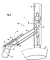
- This support structure can, as shown in Figure 3, for example, under a stage 21, which surrounds the blast furnace 12, be suspended. However, it could also be set up on the casting platform 8.
- One end of the boom 20 is in this Support structure 18 pivotally mounted.
- the location of the Pivot axis of the boom 20 in the support structure 18 through the Reference numeral 22 shown.
- the Drill mount 16 pivotally suspended.
- the location of the pivot axis of the Drill mount 16 in the boom 20 is shown by reference numeral 24.
- As a swivel drive of the boom is preferably a hydraulic motor, such as Example, a double-acting hydraulic cylinder 28 used.
- This Hydraulic cylinder 28 is Piston end is articulated on the boom 20.
- This hydraulic cylinder 28 thus enables Swiveling the boom 20 about its pivot axis 22, between the in the rest position shown in Figure 1, away from the tapping channel 13, and in Figure 2 shown working position, in the axial extension of the tap hole, directly above the launder 13.
- a control rod 30 is connected to the drilling mount 16 via a first swivel joint 32 connected.
- the other end is this control rod articulated to the support structure.
- the Control rod in the well-known tap hole drilling machine the drill carriage Swiveling between the rest position and the working position crosses, or in other words, that the boom pivots the control rod must run over or under.
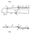
- the gear 34 is described in more detail with reference to FIGS. 4 and 5. It is a four-link transmission, the support structure 18 the Frame and the boom 20 form the driven member of the transmission.
- a first connecting link 36 is connected to the supporting structure via a swivel joint 38 18 connected.
- a second connecting member 40 is connected via a swivel joint 42 connected to the boom 20.
- These two links 36 and 40 are connected to each other via a swivel 40 so that they are the four-part Close transmission 34.
- the second end of the control rod 30 is by means of a Swivel joint 46 with the second connecting member 40 of the transmission 34 connected.
- control rod 30 the boom 20 when pivoting does not cross.
- the precise alignment of the drilling mount 16 in the working position is advantageous fixed by a length adjustment of the control rod 30.
- This The length of the control rod 30 can be adjusted, for example, by means of a and unscrewable threaded rod 48.
- the undercarriage Cantilever 20 When swiveling between its rest and work position, the undercarriage Cantilever 20 recognizes the first connecting link 36. From FIGS. 1 and 2 however, that the area of the boom 20 is that of the first Link 36 must be pivoted through, to a relative short section 50 in the immediate vicinity of the support structure 18 is limited. As can be seen from Figure 3, the connecting member 36 is in this Section 50 in a space between the bottom of the stage 21 and the Top of the boom 20 arranged. Right behind this area 50, the limit of which is indicated in FIG. 3 by the broken line 52, there is no longer any need to be provided above the boom 20. The boom 20 can consequently be graded in height, as shown in FIG. 3 with its front end 54 higher than its rear end 50.
- the Control rod 30 is located laterally in the swivel range of front end 54 (i.e. in a space that, when the boom 20 is pivoted, between Lower edge 56 and upper edge 58 of the front end 54 of the boom 20 lies). Consequently, it does not require any additional effort when pivoting Free space.
- reference numeral 60 shows that below the boom 20 swiveling taphole cannon. It is clearly evident that without one arrangement of the control rod 30 according to the invention, the free height between Platform and casting platform would not be sufficient to the boom 20 with the To pass under taphole cannon 60.
- Links 36 and 40 is just one of many possibilities. So for example, these links 36, 40 could be below the boom 20 may be arranged. It is also conceivable for the boom 20 in the area 50 to be provided with a recess through which the connecting member 36 is carried out. Such a recess is shown schematically in FIG a dashed line 62 is indicated. In these two cases, the Boom 20 of course not to be graded in height.
Landscapes
- Engineering & Computer Science (AREA)
- Chemical & Material Sciences (AREA)
- Manufacturing & Machinery (AREA)
- Materials Engineering (AREA)
- Metallurgy (AREA)
- Organic Chemistry (AREA)
- Earth Drilling (AREA)
- Jib Cranes (AREA)
- Forklifts And Lifting Vehicles (AREA)
- Blast Furnaces (AREA)
- Agricultural Machines (AREA)
- Pivots And Pivotal Connections (AREA)
- Vehicle Body Suspensions (AREA)
- Mechanical Control Devices (AREA)
- Massaging Devices (AREA)
Claims (8)
- Dispositif pivotant pour porter un organe de travail (16), comprenant :caractérisé parune structure porteuse (18) ;un bras (20), dont la première extrémité est logée de façon à pouvoir pivoter dans la structure porteuse (18), de sorte que le bras (20) peut pivoter relativement à la structure porteuse (18) autour d'un premier axe (22), l'organe de travail (16) étant relié à la deuxième extrémité du bras (20) de sorte qu'il peut pivoter autour d'un deuxième axe (24) relativement au bras (20); etune tige de commande (30) qui est articulée avec une première extrémité sur l'organe de travail (16) pouvant pivoter ;un mécanisme à quatre membres (34) comme point d'articulation pour la deuxième extrémité de la tige de commande (30), comprenant :a) la structure porteuse (18) comme bâti,b) le bras (20) comme membre actionné,c) un premier membre de liaison (36), qui est articulé avec une extrémité sur la structure porteuse (18), etd) un deuxième membre de liaison (40) qui est articulé avec une extrémité sur le bras (20) ;le premier et le deuxième membre de liaison (36 et 40) étant reliés ensemble de façon articulée, si bien que le mécanisme à quatre membres est fermé, et la tige de commande (30) étant articulée par sa deuxième extrémité au premier ou au deuxième membre de liaison (36 ou 40) du mécanisme (34).
- Dispositif pivotant selon la revendication 1, caractérisé en ce que la tige de commande (30) est disposée dans la zone pivotante du bras (20).
- Dispositif pivotant selon la revendication 2, caractérisé en ce que le premier membre de liaison (36) est disposé au-dessus ou au-dessous du bras (20).
- Dispositif pivotant selon la revendication 2, caractérisé en ce que le deuxième membre de liaison (40) est disposé avec le premier membre de liaison (36) soit au-dessus, soit au-dessous du bras (20).
- Dispositif pivotant selon l'une des revendications 1 à 4, caractérisé en ce que le bras (20) est étagé en hauteur.
- Dispositif pivotant selon l'une des revendications 1 à 5, caractérisé en ce que la tige de commande (30) est réglable en longueur.
- Dispositif pivotant selon l'une des revendications 1 à 6, caractérisé en ce que l'organe de travail est un affût de perçage (16).
- Dispositif pivotant selon l'une des revendications 1 à 6, caractérisé en ce que l'organe de travail est un canon à boucher le trou de coulée.
Applications Claiming Priority (3)
| Application Number | Priority Date | Filing Date | Title |
|---|---|---|---|
| LU90089 | 1997-07-09 | ||
| LU90089A LU90089B1 (de) | 1997-07-09 | 1997-07-09 | Schwenkvorrichtung mit Ausleger und Steuerstange |
| PCT/EP1998/004064 WO1999002738A1 (fr) | 1997-07-09 | 1998-07-01 | Dispositif de pivotement a bras et tige de commande |
Publications (2)
| Publication Number | Publication Date |
|---|---|
| EP0996748A1 EP0996748A1 (fr) | 2000-05-03 |
| EP0996748B1 true EP0996748B1 (fr) | 2001-12-12 |
Family
ID=19731698
Family Applications (1)
| Application Number | Title | Priority Date | Filing Date |
|---|---|---|---|
| EP98939597A Expired - Lifetime EP0996748B1 (fr) | 1997-07-09 | 1998-07-01 | Dispositif de pivotement a bras et tige de commande |
Country Status (8)
| Country | Link |
|---|---|
| US (1) | US6251338B1 (fr) |
| EP (1) | EP0996748B1 (fr) |
| AT (1) | ATE210737T1 (fr) |
| AU (1) | AU8805198A (fr) |
| BR (1) | BR9810573A (fr) |
| DE (1) | DE59802455D1 (fr) |
| LU (1) | LU90089B1 (fr) |
| WO (1) | WO1999002738A1 (fr) |
Families Citing this family (1)
| Publication number | Priority date | Publication date | Assignee | Title |
|---|---|---|---|---|
| GB2468910B (en) | 2009-03-27 | 2011-05-11 | Siemens Vai Metals Tech Ltd | A taphole drill |
Family Cites Families (10)
| Publication number | Priority date | Publication date | Assignee | Title |
|---|---|---|---|---|
| US1676530A (en) * | 1928-07-10 | Stopper | ||
| US1647052A (en) * | 1927-10-25 | Sotting apparatus | ||
| US1661745A (en) * | 1928-03-06 | brosius | ||
| NL162432C (nl) * | 1970-11-27 | 1980-05-16 | Wurth Anciens Ets Paul | Inrichting voor het stoppen van het afsteekgat van een schachtoven. |
| DE2822605C2 (de) | 1978-05-24 | 1987-01-15 | Dango & Dienenthal Maschinenbau GmbH, 5900 Siegen | Schwenkvorrichtung, insbesondere für Stichlochstopfmaschinen |
| US4247088A (en) | 1978-10-05 | 1981-01-27 | Ishikawajima-Harima Jukogyo Kabushiki Kaisha | Mud gun |
| LU86612A1 (de) * | 1986-09-30 | 1988-04-05 | Wurth Paul Sa | Aufhaengungs-und verankerungsvorrichtung fuer eine schienengebunden verfahrbare stopfmaschine an metallurgischen oefen |
| LU87926A1 (fr) * | 1991-04-26 | 1992-11-16 | Wurth Paul Sa | Procede de bouchage du trou de coulee d'un four a cuve et machine de bouchage pour la mise en oeuvre de ce procede |
| LU88023A1 (fr) * | 1991-10-30 | 1993-05-17 | Arbed | Lance de soufflage |
| DE19630078C2 (de) * | 1996-07-26 | 2003-03-27 | Dango & Dienenthal Maschbau | Hubvorrichtung für Stichloch-Bohrmaschinen |
-
1997
- 1997-07-09 LU LU90089A patent/LU90089B1/xx active
-
1998
- 1998-07-01 BR BR9810573-6A patent/BR9810573A/pt active Search and Examination
- 1998-07-01 WO PCT/EP1998/004064 patent/WO1999002738A1/fr not_active Ceased
- 1998-07-01 US US09/462,689 patent/US6251338B1/en not_active Expired - Fee Related
- 1998-07-01 DE DE59802455T patent/DE59802455D1/de not_active Expired - Lifetime
- 1998-07-01 AT AT98939597T patent/ATE210737T1/de active
- 1998-07-01 EP EP98939597A patent/EP0996748B1/fr not_active Expired - Lifetime
- 1998-07-01 AU AU88051/98A patent/AU8805198A/en not_active Abandoned
Also Published As
| Publication number | Publication date |
|---|---|
| EP0996748A1 (fr) | 2000-05-03 |
| WO1999002738A1 (fr) | 1999-01-21 |
| ATE210737T1 (de) | 2001-12-15 |
| BR9810573A (pt) | 2000-09-19 |
| US6251338B1 (en) | 2001-06-26 |
| LU90089B1 (de) | 1999-01-11 |
| DE59802455D1 (de) | 2002-01-24 |
| AU8805198A (en) | 1999-02-08 |
Similar Documents
| Publication | Publication Date | Title |
|---|---|---|
| DE2815454A1 (de) | Befestigungsanordnung fuer ein gegengewicht | |
| EP1593294B1 (fr) | Dispositif d'accouplement pour faucheuse | |
| EP1636503B1 (fr) | Palier entre des composants de machines de construction | |
| DE2602142A1 (de) | Schwenkbolzen fuer bagger-bauteile sowie verfahren zu dessen einbau | |
| DE2448367A1 (de) | Grubendeckenstuetze | |
| DE1658032A1 (de) | Materialbehandlungsmaschine | |
| EP0996748B1 (fr) | Dispositif de pivotement a bras et tige de commande | |
| DE1484758A1 (de) | Hydraulischer Bagger,insbesondere Planierbagger | |
| DE3148982A1 (de) | Hydraulisch betaetigbare einrichtung an greifern zum daempfen von schwingbewegungen des greiferarmrahmens | |
| DE60016356T2 (de) | Multifunktions-Steuermechanismus und Fahrzeug mit einem Steuermechanismus | |
| EP0321902B1 (fr) | Dispositif de fixation d'un outil sur un engin de terrassement | |
| CH665237A5 (en) | Bulldozer blade mounting - has double acting rams with linkage on horizontal vehicle axis to blade end hinge | |
| DE69520119T2 (de) | Gezogenes landwirtschaftliches Gerät | |
| DE2625680C3 (de) | Fahrbarer Hydraulikbagger | |
| DE102005024469A1 (de) | Vorrichtung zum Bearbeiten von Strassenbauflächen | |
| DE2928278A1 (de) | Front- oder hecklader | |
| DE60217565T2 (de) | Raupenfahrzeug mit oszillierenden Gleiskettenlaufwerken | |
| WO1998032881A1 (fr) | Foreuse a trous de coulee | |
| AT407422B (de) | Schrämmaschine | |
| DE2501177A1 (de) | Verfahren zum umsetzen einer fuehrerkabine einer baumaschine, sowie baumaschine zur durchfuehrung dieses verfahrens | |
| DE19611582C2 (de) | Mähfahrzeug mit einem Sammelbehälter | |
| DE69914424T2 (de) | Frontladerausleger | |
| DE3447192C2 (de) | Hobel für die untertägige Gewinnung | |
| DE19514013A1 (de) | Vorrichtung zum Anbau eines Vorbauarbeitsgerätes | |
| DE3233581A1 (de) | Anstellwinkelsteuerung der grabschaufel einer hydraulikbagger-tiefloeffelausruestung |
Legal Events
| Date | Code | Title | Description |
|---|---|---|---|
| PUAI | Public reference made under article 153(3) epc to a published international application that has entered the european phase |
Free format text: ORIGINAL CODE: 0009012 |
|
| 17P | Request for examination filed |
Effective date: 19991122 |
|
| AK | Designated contracting states |
Kind code of ref document: A1 Designated state(s): AT DE GB IT |
|
| GRAG | Despatch of communication of intention to grant |
Free format text: ORIGINAL CODE: EPIDOS AGRA |
|
| 17Q | First examination report despatched |
Effective date: 20010329 |
|
| GRAG | Despatch of communication of intention to grant |
Free format text: ORIGINAL CODE: EPIDOS AGRA |
|
| GRAH | Despatch of communication of intention to grant a patent |
Free format text: ORIGINAL CODE: EPIDOS IGRA |
|
| GRAH | Despatch of communication of intention to grant a patent |
Free format text: ORIGINAL CODE: EPIDOS IGRA |
|
| GRAA | (expected) grant |
Free format text: ORIGINAL CODE: 0009210 |
|
| AK | Designated contracting states |
Kind code of ref document: B1 Designated state(s): AT DE GB IT |
|
| PG25 | Lapsed in a contracting state [announced via postgrant information from national office to epo] |
Ref country code: IT Free format text: LAPSE BECAUSE OF FAILURE TO SUBMIT A TRANSLATION OF THE DESCRIPTION OR TO PAY THE FEE WITHIN THE PRE;WARNING: LAPSES OF ITALIAN PATENTS WITH EFFECTIVE DATE BEFORE 2007 MAY HAVE OCCURRED AT ANY TIME BEFORE 2007. THE CORRECT EFFECTIVE DATE MAY BE DIFFERENT FROM THE ONE RECORDED.SCRIBED TIME-LIMIT Effective date: 20011212 |
|
| REF | Corresponds to: |
Ref document number: 210737 Country of ref document: AT Date of ref document: 20011215 Kind code of ref document: T |
|
| REG | Reference to a national code |
Ref country code: GB Ref legal event code: IF02 |
|
| GBT | Gb: translation of ep patent filed (gb section 77(6)(a)/1977) |
Effective date: 20011212 |
|
| REF | Corresponds to: |
Ref document number: 59802455 Country of ref document: DE Date of ref document: 20020124 |
|
| PLBE | No opposition filed within time limit |
Free format text: ORIGINAL CODE: 0009261 |
|
| STAA | Information on the status of an ep patent application or granted ep patent |
Free format text: STATUS: NO OPPOSITION FILED WITHIN TIME LIMIT |
|
| 26N | No opposition filed | ||
| REG | Reference to a national code |
Ref country code: HK Ref legal event code: WD Ref document number: 1027600 Country of ref document: HK |
|
| PGFP | Annual fee paid to national office [announced via postgrant information from national office to epo] |
Ref country code: GB Payment date: 20140617 Year of fee payment: 17 |
|
| PGFP | Annual fee paid to national office [announced via postgrant information from national office to epo] |
Ref country code: DE Payment date: 20140617 Year of fee payment: 17 |
|
| PGFP | Annual fee paid to national office [announced via postgrant information from national office to epo] |
Ref country code: AT Payment date: 20140618 Year of fee payment: 17 |
|
| REG | Reference to a national code |
Ref country code: DE Ref legal event code: R119 Ref document number: 59802455 Country of ref document: DE |
|
| REG | Reference to a national code |
Ref country code: AT Ref legal event code: MM01 Ref document number: 210737 Country of ref document: AT Kind code of ref document: T Effective date: 20150701 |
|
| GBPC | Gb: european patent ceased through non-payment of renewal fee |
Effective date: 20150701 |
|
| PG25 | Lapsed in a contracting state [announced via postgrant information from national office to epo] |
Ref country code: GB Free format text: LAPSE BECAUSE OF NON-PAYMENT OF DUE FEES Effective date: 20150701 Ref country code: DE Free format text: LAPSE BECAUSE OF NON-PAYMENT OF DUE FEES Effective date: 20160202 |
|
| PG25 | Lapsed in a contracting state [announced via postgrant information from national office to epo] |
Ref country code: AT Free format text: LAPSE BECAUSE OF NON-PAYMENT OF DUE FEES Effective date: 20150701 |