EP0996832B1 - Double volant amortisseur de torsion, notamment pour vehicule automobile - Google Patents
Double volant amortisseur de torsion, notamment pour vehicule automobile Download PDFInfo
- Publication number
- EP0996832B1 EP0996832B1 EP99918022A EP99918022A EP0996832B1 EP 0996832 B1 EP0996832 B1 EP 0996832B1 EP 99918022 A EP99918022 A EP 99918022A EP 99918022 A EP99918022 A EP 99918022A EP 0996832 B1 EP0996832 B1 EP 0996832B1
- Authority
- EP
- European Patent Office
- Prior art keywords
- hub
- mass
- flange
- flywheel according
- washer
- Prior art date
- Legal status (The legal status is an assumption and is not a legal conclusion. Google has not performed a legal analysis and makes no representation as to the accuracy of the status listed.)
- Expired - Lifetime
Links
Images


Classifications
-
- F—MECHANICAL ENGINEERING; LIGHTING; HEATING; WEAPONS; BLASTING
- F16—ENGINEERING ELEMENTS AND UNITS; GENERAL MEASURES FOR PRODUCING AND MAINTAINING EFFECTIVE FUNCTIONING OF MACHINES OR INSTALLATIONS; THERMAL INSULATION IN GENERAL
- F16F—SPRINGS; SHOCK-ABSORBERS; MEANS FOR DAMPING VIBRATION
- F16F15/00—Suppression of vibrations in systems; Means or arrangements for avoiding or reducing out-of-balance forces, e.g. due to motion
- F16F15/10—Suppression of vibrations in rotating systems by making use of members moving with the system
- F16F15/12—Suppression of vibrations in rotating systems by making use of members moving with the system using elastic members or friction-damping members, e.g. between a rotating shaft and a gyratory mass mounted thereon
- F16F15/131—Suppression of vibrations in rotating systems by making use of members moving with the system using elastic members or friction-damping members, e.g. between a rotating shaft and a gyratory mass mounted thereon the rotating system comprising two or more gyratory masses
- F16F15/13164—Suppression of vibrations in rotating systems by making use of members moving with the system using elastic members or friction-damping members, e.g. between a rotating shaft and a gyratory mass mounted thereon the rotating system comprising two or more gyratory masses characterised by the supporting arrangement of the damper unit
-
- F—MECHANICAL ENGINEERING; LIGHTING; HEATING; WEAPONS; BLASTING
- F16—ENGINEERING ELEMENTS AND UNITS; GENERAL MEASURES FOR PRODUCING AND MAINTAINING EFFECTIVE FUNCTIONING OF MACHINES OR INSTALLATIONS; THERMAL INSULATION IN GENERAL
- F16F—SPRINGS; SHOCK-ABSORBERS; MEANS FOR DAMPING VIBRATION
- F16F15/00—Suppression of vibrations in systems; Means or arrangements for avoiding or reducing out-of-balance forces, e.g. due to motion
- F16F15/10—Suppression of vibrations in rotating systems by making use of members moving with the system
- F16F15/12—Suppression of vibrations in rotating systems by making use of members moving with the system using elastic members or friction-damping members, e.g. between a rotating shaft and a gyratory mass mounted thereon
- F16F15/131—Suppression of vibrations in rotating systems by making use of members moving with the system using elastic members or friction-damping members, e.g. between a rotating shaft and a gyratory mass mounted thereon the rotating system comprising two or more gyratory masses
- F16F15/133—Suppression of vibrations in rotating systems by making use of members moving with the system using elastic members or friction-damping members, e.g. between a rotating shaft and a gyratory mass mounted thereon the rotating system comprising two or more gyratory masses using springs as elastic members, e.g. metallic springs
- F16F15/134—Wound springs
- F16F15/13407—Radially mounted springs
Definitions
- second fixing means intervene between the outer peripheries of the disc support and the support flange.
- a plate is attached to the flange for allow the friction means to increase in its thickness.
- the support disc extends radially above the reaction plate and has a shape tortuous. The aforementioned plate is interposed between the flange and the support disc.
- This extension then presents at its free end ventilation fins.
- the first hub internally advantageously serves as housing at the hub of the clutch friction disc friction to which the reaction plate belongs.
- the pilot bearing is carried internally by the first hub via a self-adjusting ring comprising at least a slit. This ring avoids recovery operations and allows to use a thin tubular hub.
- This double steering wheel has at least three parts, namely the starter ring support disc, which can be in one piece with this disc, the support flange and a guide washer or a closing washer integral with the end of the flange of the support flange.
- the support disc can be standard whatever the type of double steering wheel.
- the guide washer or the closing washer have a large internal diameter.
- the support flange is centered by the first hub being fixed on the first hub.
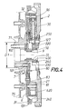
- FIG. 4 is a view analogous to FIG. 3 with bearing means in the form of plain bearing
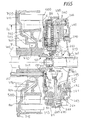
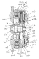
- FIGS. 5 and 6 are views similar to the Figure 3 with the presence of an electric machine.
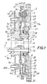
- the bearing means intervene here between the outer periphery of the first hub 5, 50 and the periphery internal of the second mass 2 hole centrally for this purpose.
- the coating is a quasi-crystalline coating.
- the bearing means 4, 40 consist of ball bearings.
- the first hub 5, 50 is, at its outer periphery, stepped in diameter to form a shoulder allowing the ring to be axially aligned in one direction internal of ball bearing 4, 40 fitted on end free of smaller diameter of the first hub 5, 50.
- the inner ring of the bearing 4, 40 is axially fixed respectively by a support washer 51 ( Figures 1 and 2) and by a circlip 260 ( Figure 3) mounted in a groove made at the free end of the first hub 50.
- the second mass 2 has at its internal periphery a internal hub 22 ( Figures 1 and 2), 220 ( Figure 3) shouldered internally above the support washer 51 or circlips 260 for mounting in its internal bore of the ring outside of ball bearing 4, 40 and axial setting thereof in a sense.
- the two masses 1, 2 are mounted movable in rotation relative to each other at against elastic members 3 (Figures 1 and 2), 30 ( Figure 3) and friction means 8 ( Figures 1 and 2), 80 ( Figure 3) with axial action.
- the elastic members 30 work in compression and can naturally be replaced by tension springs.
- the organs elastic 3, 30 are coil springs.
- the first mass 1 is intended for be attached to the vehicle engine crankshaft.
- This first mass 1 is connected elastically to the second mass by the elastic members 3, 30, which, as a variant, may consist of blocks of elastic material such as the elastomer.
- a torsion damper with elastic members 3, 30 therefore intervenes between the two masses 1, 2.
- the damper of torsion is therefore installed axially between the two masses.
- the axial action friction means 8, 80 belong to this torsional damper and have a friction washer driven, possibly after catching a game, by the second mass 2 and rubbing against two surfaces of the first mass 1.
- the friction washer is carried by the first mass.
- the second mass 2 is therefore disengageably connected to the input shaft of the gearbox by the disc of friction with a central hub at its internal periphery internally grooved for its rotational connection to the shaft input of the gearbox.
- the first hub 5, 50 extends the second axially hub 7.
- These hubs 5, 50-7 have the same axis of axial symmetry namely the X-X axis. They have a cylindrical shape here and are axial orientation.
- Centering means operate between the first hub 5, 50 and the second hub 7 to center the hubs 5, 50-7 relative to each other so that these have the same axis of axial symmetry X-X.
- pilot bearing 9 is worn internally by the first hub 5, 50, while in the figure 2, the pilot bearing 9 is carried internally by the second hub 7.
- the sleeve comes from one of the elements, first hub 5, 50-second hub 7 and cooperate with the inner periphery of the other of the second hub elements 7-first hub 5, 50 says ci after second element.
- the outer periphery of the sleeve is in intimate contact with the internal periphery of the second element formed by the internal bore of the second element.
- the sleeve goes inside the second element and carries inside the pilot bearing 9, which, as a variant, can be replaced by a plain bearing with a low coefficient of friction or by a carbon diamond amorphous coating.
- the sleeve carries, in all cases, a bearing pilot 9 for the free end of the input shaft of the gearbox of speeds or, generally for the free end of a led tree.
- the sleeve 76 surrounds the recess so that it is formed an annular cavity thanks to the hollow 71 and the sleeve 76.
- a seal sealing 77 in elastic contact with the second hub 7 and immobilized axially and in rotation by the bush 76. It is thus formed a joint 77, called a rotating joint, preventing engine oil to escape.
- the end of the leading tree, here the crankshaft is therefore simplified by the fact that the seal seal 77 is not in contact with the crankshaft, which, thus, is shorter axially.
- the second hub 7 is here metallic being in a less expensive material than that of crankshaft whose free end is provided for example with a toothing for a movement transmission belt. The second hub partially penetrates inside the housing of the internal combustion engine.
- the second hub 7 is in sintered material.
- the second hub 7 is made of moldable material.
- the wall 74 forms a plug for the holes 70, because that it extends at its outer periphery facing them.
- the hub 7 is therefore also a protective hub against any pollution, a hole closure hub 70, a contact hub for seal 77, and a contact hub stop for the flange 6.
- the support disk 32 double in thickness the flange 6 and this, radially above the wall 74, generally of the same thickness at its periphery external than that of the support disc 32, here thick constant.
- the inertia of the first mass 1 is therefore increased simply and economically, especially since the crown starter 31, having teeth 131 intended to cooperate with the vehicle starter when starting the engine vehicle, is located at the outer periphery of the disc 32.
- the said channel is therefore delimited by the wall 75, by the disc 32 and the wall 74.
- This annular channel is blind; the bottom of this channel being formed by the two grooves 72 and 73 of the second hub.
- the wall 75 is parallel to the disc 32 and to the support flange 6.
- the second groove 73 is deeper than the first groove 72.
- This second groove 73 is also more wide than the first groove 72 so that the second groove 73 has a size larger than the first recovery throat 72 oil leaks.
- the second hub 7 has a extra thickness in which the first groove 72 is formed thus extending radially above the second groove 73, and the wall 74 is shorter and extends radially below holes 70 opposite the internal periphery of the flange 6 axially offset towards the reaction plate.
- the internal periphery of the flange 6 is connected to the part main flange by an inclined or rounded area forming deflector and extending above the wall 74. Thus, the holes 70 are protected.
- the support disc 32 has at its external periphery a peripheral section (not referenced) axially offset towards the reaction plate 21 by compared to the main part of this disc 32 extending transversely, that is to say perpendicular to the axis X-X.
- the teeth of the crown 31 are parallel to the X-X axis.
- This crown 31 is hollowed out at its internal periphery at its face facing away from the reaction plate 21.
- the disc 32 by its peripheral section penetrates into this hollow. Welding is carried out between the periphery internal of the crown 31 and the face of the disc 32 facing the reaction plate 21, and this just above the holes 36, which thus guarantee good flatness.
- the flange external device 25 of the reaction plate 21 extends radially above the annular rim 61, 610 of the flange 6 and is directed axially towards the crown 31.
- the support disc 32 can have at its outer periphery an axial orientation zone with two separate sections offset radially from one another the other as described for example in document FR-A-2 526 106.
- one of the axial sections wears the starter ring gear 31, while the other axial section carries an ignition target, in this case, the one closest to the reaction plateau 21.
- the target is an integral part of the axial zone, which connects to the main transverse orientation part of the disc 32 by an inclined connection area.
- the axial zone alternatively can carry fins at its free end ventilation.
- the second mass 2 presents at its inner periphery, radially below; the face of friction 29, plate 21, ventilation holes 23 ( Figures 1 and 2), 230 ( Figure 3), so that an air flow, favored by the fins 240, takes place between the internal face of the plate of reaction 21, turned away from the friction face 29, and the first mass 1.
- the plate 21, as well as the bearing means 4, 40 are well cooled.
- the fins 240 are very effective from the fact that, apart from crown 31, they are installed, as well as the rim 25, radially above of the first mass 1 on a circumference of large diameter. In this figure 3, the fins 240 are located radially below the teeth of the crown 31.
- riveting can be replaced by a welding, for example transparency welding using a laser.
- a first internal fixing zone 34 therefore intervenes between the flange 6 here metallic and the support disc 32 here metallic.
- the disc 32 is attached to the flange 6.
- the disc 32 is in contact with the flange 6 only at these internal fixing zones 34 and external 33, so that a good transverse orientation of the flange 6.
- the flange 6 has zones support planes 37 at its outer periphery for fixing the disc 32 using rivets 33.
- the rivets internal fixing 34 of Figures 1 and 2 are aligned axially with the ventilation holes 23, which may have a flared shape towards the first mass 1.
- the holes 23 may be cylindrical or circumferentially shaped oblong.
- the second hub 7 locally presents a series of recesses (not referenced) for housing rivet heads 53 passing through axially aligned holes in the flange 6, the first hub 5 and the washer 51.
- a subassembly forming a double damping flywheel torsion comprising the first mass 1, coupled the second mass 2 by the above-mentioned torsional damper, which then add using the screws 10 on the second hub 7 and the crankshaft.
- the flange 6 is fixed by welding. More specifically, a weld bead 54 intervenes between the internal periphery of the flange 6 and the periphery outer of the first tubular hub 50.
- the weld bead 54 is located on the side of the flange 6 opposite the second hub 7.
- the first hub 50 carries the bearing at its free axial end 40.
- the fixing is carried out by crimping, the flange 6 having teeth on its internal cutting edge grooves in the hub 50 having a support shoulder for the flange 6. By crushing the material of the hub 50 in contact of the flange 6, the flange is fixed.
- the ring 55 is mounted inside the tubular hub 50, at the front or back of it.
- the ring 55 is shouldered to cooperate here with the edge of the axial end of the hub 50 opposite the bearing 40.
- the ring has at least one slot and is interposed radially between the internal periphery of the hub 50 and the outer periphery of the pilot bearing. This provision is applicable in Figures 1 and 2.
- the ring 55 reduces the thickness of the tube 50 constituting as much as possible the first hub and avoids having to machine the first hub.
- the ventilation holes 230 have another function. They have a cylindrical shape and allow the passage of at least one tool for the screwing of fixing 101 used to assemble the flange 6, and therefore the first mass 1, at the second hub 7.
- the screws 101 are short.
- the screw heads 101 have indentations for the or the screwing tools.
- the double damping flywheel with its two masses 1, 2 is attached by the screws 101 on the second hub 7 with centering between the two hubs 7, 50 thanks to the first hub 50 extending in axial projection relative to the flange 6, to form in the aforementioned manner, a sleeve centering.
- the second hub 7 is fixed in advance to the crankshaft of the vehicle engine using the aforementioned fasteners 100 or any other means of attachment.
- These organs 100 consist here in screws 100 shorter than those of Figures 1 and 2.
- the screws 100 are longer than the screws 101, which may have a diameter smaller than that of the screws 100. Indeed, the screws 100 only pass through the second hub 7 to screw into the crankshaft.
- the second hub 7 is hollowed out locally at its internal periphery for housing the screw heads 100, here at cylindrical heads with indentations like screws 101.
- the flange 6 covers the screw head 100 and that the first hub 50 is centered in the second hub 7.
- the first hub 5 presents at its inner periphery, on the side opposite to the bearing 4, a sleeve 60 axial, serving as a centering device for the flange 6 by its periphery external in intimate contact with the internal periphery of the flange 6.
- the outer periphery of the sleeve 60 is in intimate contact with the inner periphery (the inner bore) of the second hub 7 coming to center on the sleeve 60 before its fixing to the crankshaft.
- the flange 6 is centered by the first hub 5, 50.
- the first hub 5 and the second hub 7 have internal bores stepped in diameter for a except that the friction disc hub can penetrate the first hub 5 and, on the other hand, for mounting the pilot bearing 9 with an outer diameter smaller than that of the disc hub friction.
- the first hub 5 therefore has an additional internal bore small diameter at its end near the second hub and an internal bore of larger diameter at its end for penetration of the friction disc hub.
- the change in diameter of the bore internal of the first hub 50 is produced by means of the ring 55, which thus avoids having to internally store the first hub 50 and therefore simplifies manufacturing.
- the machining is advantageously reduced, the ring 55 has several slots evenly distributed.
- the double damping flywheel of the Figures 1 to 3 can also be seen on the crankshaft with or not a centering sleeve 160.
- the end of the crankshaft has a hole centrally when for the relative centering between the first hub 5, 50 and the crankshaft in an identical manner to the embodiments of FIGS. 1 to 3.
- we form a unitary double flywheel torsional damper thanks to fixing, using rivets 53 or welding the flange 6 on the first hub. The subset is then fixed either on a second hub or on the crankshaft.
- This double steering wheel can be fitted with elastic members 3, 30.
- double steering wheel is for example of the type described in the document FR-A-2 736 116 to which reference may be made for further details.
- the outer periphery of the web 26 is axially offset towards the flange 6 relative to the internal periphery of the web 6 in contact with the internal face of the internal hub.
- the rivets 27 are opposite holes 70.
- the springs 3 are pre-bent and have a curved shape.
- the veil 26 has arms inside the housing 63, for example in FIG. 2 of document FR-A-2 736 116.
- the arms and therefore the web 26 extend radially between the flange 6 and the guide washer 62.
- the washer seal 66 is fixed on the flange 6 in a characteristic using internal rivets 34 for fixing the disc 32 at the flange 6.
- the washer 66 is inclined in the direction of the web 26 and is supported at its outer periphery on this web 26.
- the sealing washer 67 is fixed to the web 26 using a series of rivets 134 implanted opposite the holes 23 in axial alignment therewith.
- the rivets 134 are formed by extrusion from the web 26 here in sheet metal Pressed.
- the washer 67 is supported at its outer periphery on the guide washer 62 at the internal periphery thereof being located radially above the rivets 134, 34, 27.
- the washer 67 is generally flat.
- the wall 74 replaces the plugs known for example from document FR-A-2 736 116 and the rivets 27 has a hollow head forming a pin 28 to drive in rotation, possibly after catching a game circumferential, a friction washer belonging to friction means with axial action 8.
- These means 8 are for example type of those described in document FR-A-2 736 116 and therefore have a friction washer provided at its periphery external notches into which penetrate, without play or with circumferential play, the pins 28 for driving in rotation of the friction washer by the second mass 2.
- the friction washer bears against the transverse shoulder of the first hub 5 and against a application washer linked in rotation to the first hub at the favor of radial lugs, forming tenons, penetrating into axial grooves, forming mortises, produced in a extra thickness 52 with an external diameter greater than that of the free end of the first hub carrying the bearing 4.
- the application washer is subjected to the action of a washer elastic with axial action, here a Belleville washer, in support on a locking circlip mounted in an annular groove made in the extra thickness 52 of the first hub 5.
- the spring washer clamps the friction washer between two faces or surfaces of the first mass 1 and during a movement relative between the two masses 1, 2, the friction washer, driven by the second mass 2, rubs against the two surfaces of the first mass 1.
- the flange 61 of the flange is stepped in diameter at its outer periphery and has a section at its free end external of larger diameter connected by a shoulder to the rim 61 proper.
- the shoulder is used for axial setting in one direction of the guide washer 62 mounted inside the outer section of the flange 6.
- the guide washer 62 at its outer periphery, is in intimate contact, therefore centered, with the inner periphery of the outer section of the flange 61.
- the fixing from the washer 62 to the rim 61 of the flange 6 is produced by welding of the free ends of the outer section of the flange 6 and of the axial orientation ring that the washer 62 has its outer periphery. It is this ring which is threaded to inside the outer section of the rim 61 and allows the centering of the washer 62.
- Welding consists of a weld bead.
- the tray reaction 21 has an internal face, directed towards the first mass 1, dug in 24 to reduce the size axial.
- the recess 24 has a trapezoidal shape. At a relative angular movement between the two masses, the web 26 moves relative to the flange 6 and the guide washer 62 with compression of the springs 3.
- the presence of the washer ring 62 allows stiffening of said washer 62.
- the zones 37 belong to the top of the stampings 68 of the flange 6, directed outwards in the opposite direction to the sail 26.
- the stampings 68 are connected to a part transverse 164 in the plane of the deformations 64.
- the part 164 is therefore extended by the deformations 64 spring support and is connected at its internal periphery to the inner periphery of the flange 6, which is in the plane of the supports 37.
- the friction means 80 are worn by the flange 6 for supporting the first mass 1. These means 80 extend radially above the bearing 40 and the screws fixing 100, 101.
- These means 80 include pins 128 belonging to pins 127 shaped to form rivets at their ends opposite the pawn.
- the flange 6 has holes axially in with respect to the pins 128. These non-referenced holes are closed by the free axial end of the second hub 7.
- the journals 127 through holes through the internal hub 220 as described for example in document EP-A-0 798 490.
- the pins 127 therefore pass through an elastic washer with axial action (not referenced) and have a crushed head in contact with the washer elastic and a locking collar in contact with the face of the internal hub 220, directed towards the flange 6.
- the washer elastic with axial action belongs to the torque limiter 250.
- the washer has here at its outer periphery a part inclined in the shape of a Belleville washer. This part is connected at its internal periphery to a connection part it even connected to the inner periphery of the spring washer crossed by the pins 127.
- connection part has holes (not referenced) in which engage, in a complementary manner, internal tabs, belonging to an application washer (not referenced).
- the application washer belongs to torque limiter 250 and is linked in rotation by its legs internal to the axial action spring washer.
- the application washer forms one of the lateral flanks a groove into which an internal ring engages (not referenced) of transverse orientation that includes the reaction 21 at its internal periphery.
- the axial action resilient washer of the torque 250 is supported on the application washer to tighten the inner ring of the reaction plate between the sides sides of the groove, i.e. between the washer of application and the veil of the internal hub.
- the tightening of the spring washer is such that no movement of rotation does not occur between the internal hub 220 and the plate reaction 21, rotatably mounted on the bottom of the groove. In case of overcut, a relative slip occurs between the plate 21 and the hub 220.
- the closing washer 620 is fixed by a cord of welding at the free end of the flange 610.
- spacers 81 stepped in diameter, connect the closing washer 620 to the flange 6. Rivets 82 through the holes through the spacers 81, the flange 6 and the washer 620 to secure the spacers to the flange 6 and the washer 620 thus fixed by two zones of fastening, offset radially from each other, to the flange 6.
- the spacers 81 extend radially above the internal fixing rivets 34.
- Rivets 34 pass through axially openings aligned made in the disc 32, the flange 6, a plate 83 metallic and a cover washer 84.
- the rivets 34 ensure therefore also the attachment of parts 83, 84 to the flange 6.
- the disc 32 and the plate 83 here in stamped sheet metal, are arranged on either side of the flange 6, radially above of the wall 74 of the second hub 7.
- the washer 84 is axially elastic and belongs to the friction means to axial action 80.
- the elasticity of the washer 84 is obtained for example by endowing the intermediate portion of the washer 84 with slots oblong.
- the washer 84 has a frustoconical shape in the free state and is inclined towards the flange 6.
- the plate 83 is also fixed to the flange 6 in favor spacers 81.
- the spacers 81 and the plate 83 therefore allow to further increase the inertia of the first mass and this, simple and economical way.
- the disc 32 is drilled opposite the rivets 82, while the washer 620 is hollowed out for housing the feet of the rivets 82.
- the spacers 81 and the rivets 82 secure the washer 620 and the plate 83 at the flange 6.
- the plate 83 at its outer periphery axially offset in the direction of the mass to clear the area for connecting the rim 610 to the flange 6.
- the plate 83 has notches at its periphery internal which engage radial legs that has an application washer at its internal periphery.
- the application washer belongs to the means of friction 80 and provides a friction face to a washer of friction in contact with the internal face of the flange 6 turned towards the second mass 2.
- a first friction washer is clamped between the inner face of the flange 6 and the application washer under the action of a resilient washer with axial action, here a Belleville washer not referenced, based on the cover washer 84 to apply the application washer, axially movable in the direction of the flange 6.
- a resilient washer with axial action here a Belleville washer not referenced
- the cover washer 84 bears on its internal periphery on a second friction washer to stress axially this in the direction of the internal face of the flange 6.
- the second friction washer is made of material synthetic and meshes at its inner periphery with pawns 128. To do this, the second friction washer has its internal periphery of the notches in which penetrate in addition, the pawns 128.
- the second washer of friction has male teeth, while the first friction washer has at its inner periphery a female teeth.
- Each set of teeth has alternating teeth and advantageously notches of trapezoidal shape.
- the teeth of the male teeth penetrate play in the notches of female teeth and screws. It is thus formed means of circumferential backlash.
- the first friction washer is delayed after taking up the circumferential play of the meshing means at play.
- the springs 30 therefore work in compression during a relative movement between the two masses and belong to cassettes comprising the housing 87, the piston 88 and the rod 89.
- the springs 30 can be replaced by extension springs with end loops engaged on the pins 127.86.
- the disc 32 can come very close screw heads 200 projecting from the wall 75 of the casing of the internal combustion engine.
- chutes can be interposed between the outer periphery of the springs 3 and the housing 63.
- the first hub 50 is a tube and therefore forms at its end opposite to the bearing 40 a centering sleeve like sleeve 60 of the Figure 1.
- the first hub 50 is therefore very thin which allows on the one hand to further reduce the size of the means bearing 40 located below the ventilation holes 230 and passage of at least one tool for fixing the screws 100, 101 and on the other hand, to further lengthen the cassettes and the springs 30.
- the springs 3 may not be lubricated as described for example in document FR-A-2 166 604.
- the cassettes of the springs 30 are distributed circumferentially evenly in a star.
- the cassettes alternate circumferentially with the spacers 81 increasing the inertia of the primary mass.
- the second hub 7 constitutes, by its free end, an axial support stop for the flange of support 6, more precisely for the internal periphery of the support flange.
- the screws 100, 101 can be implanted on different diameters instead of being distributed so circumferentially alternated globally on the same circumference (figure 3).
- the rim 25 of the reaction plate 21 can be extended axially in the direction of the starter ring 31 by ventilation fins 340 distributed circumferentially from on a regular basis.
- the fins 340 extend radially partly above the crown 31.
- the crown of starter 31 can have fins 440 in association with the fins of the second mass.
- the fins of the tray reaction 21 are then shorter axially.
- the fins are inclined or curved for good performance.
- the hollow 71 is formed by changing the diameter of the second hub 7, which thus has an end adjacent to the crankshaft of lower diameter D1.
- the crankshaft therefore has one end of diameter D1 less than the main part of the second hub 7.
- the second hub 7 therefore has a size greater than that of the end of the crankshaft.
- first hub of figure 4 does not differ not that of FIG. 3, starting from the axial elongation of the bearing surface bearing 400 axially blocked by the circlip 260 and the change in diameter as in Figure 3.
- the plate 83 can easily be accommodated 80 between the flange 6 and the spring cassettes 30 without increase in axial dimensions.
- the second hub 7 can present a pawn engaging in the flange 6 and / or the first hub 5 to form a polarizer.
- This rotor 500 and the stator 700 are coaxial parts mounted radially one above the other with presence an air gap 800 between the rotor 500 and the stator 700.
- Ribs 704 connect the ends of the sleeve to the second veil 701.
- the second hub 7 carries second bearing means 710, here a ball bearing, located at the root of the veil 701 of the side of it facing the drive shaft 300.
- the inner ring of the bearing 710 is fitted on the second hub, while the outer ring of the bearing is fitted into a shoulder socket 711 belonging to the outer periphery of a load-bearing part 712, having at its outer periphery a skirt 713 and ears with holes 715 for attachment of part 712 to the fixed wall of the motor housing (not shown) using screws (not shown).
- the number depends on the application.
- Part 712 has a tortuous shape to come at most near the rotor 500, the sleeve 702 and the web 701.
- This part 712 is ribbed in 714 and is intended to be fix on the engine block of the vehicle using screws (not visible).
- the air gap between the rotor 500 and the stator 700 is thus precise thanks to the second bearing means 710.
- the second hub 7 can enter the motor as in Figures 1 to 4 and have a recess, for receiving a seal, as well as a first throat.
- the skirt 713 and the sleeve 702 have conical parts as well as packets of sheets.
- the stator 700 has windings of electric wires connected to a control and power unit. So the machine 600 forms an alternator and a starter for the combustion engine internal.
- the machine here of the asynchronous type can be of the type synchronous and therefore present magnets mounted in the air gap 800 or buried.
- Machine 600 can be radial flow or axial.
- the machine is magnet flux switching single or hybrid, brushless claw, variable reluctance, single and double existences, transverse effect flow varnished.
- This machine 600 filters vibrations, brake and accelerate the vehicle's engine. For more details, see document WO98 / 05832.
- the first mass of the double torsional damping flywheel therefore carries, via the second hub 7, the rotor 500 an electric machine 600.
- the first mass of the double torsional damping flywheel therefore carries, via the second hub 7, the rotor 500 an electric machine 600.
- 260 we see in 260 the linings of friction of the friction disc 261 having a hub 302 rotatably coupled to the driven shaft 301.
- the linings of friction 261 are integral with a support 262 fixed by riveting on a web 263 fixed by crimping on the hub 302.
- the linings 260 are therefore rigidly coupled to the hub 302.
- 264 we see at 264 the pressure plate linked at rotation, with axial mobility, to the cover 265 by tangential tabs 266.
- the reaction plate 21 has at its periphery external an annular skirt 350 of axial orientation coming here from molding with the plate 21.
- the skirt 350 is directed axially in the opposite direction with respect to the edge 25 of FIG. 3.
- the cover 265 has at its outer periphery a radial flange 267 drilled for fixing by screws 268 to the skirt 350 surrounding the linings 260.
- the cover 265 carries pivotally the diaphragm 269; here, using posts 270 axially passing through the diaphragm 269 for wear a rolled crown with support to rivet secondary 271 at the diaphragm 269 opposite a primary support 272 formed by stamping in the cover 269.
- a clutch release bearing shown schematically in 273
- the diaphragm 269 is pivoted to disengage the clutch.
- the support flange 6 is integral with the plate 83 as in Figure 3, but disk 32 is modified and is implanted on the other side of the flange 6.
- the disc 32 is of a in one piece with the closing washer 620 forming with the puddle 6 of the cages in which the spacers are mounted 81, with the presence of two sets of rivets 34, 82 as in the Figure 3.
- the plate 83 is sandwiched between the disc 32 and the flange 6.
- Rivets 82 are only used to fix the spacers 81, flange 6, single piece disc 32 - washer closing 620.
- This part 32-620 is made of stamped sheet metal.
- the washer closure 620, and therefore disc 32 present at its periphery external an annular rim of axial orientation surrounding the skirt 350.
- the rest of the torsion damping flywheel is identical to that of FIG. 3.
- a series of screws 10 fixes the hubs 50, 7 to crankshaft 300, as in figure 2.
- the first hub 50 has a radial web 150.
- the flange 6 bears against the face of the sail 150 facing away from the second hub.
- the screws 10 pass through the flange 6, the web 150 and the second hub 7 for screw into the crankshaft.
- the flange 6 is associated with the first hub 50.
- the flange 6 can be fixed by welding or gluing on the veil 150.
- the flange 6 is riveted to the web 150, the second hub 7 then having recesses as in the figure 1 for housing the heads of the fixing rivets.
- the flange 6 is free.
- the machine 600 is transformed into a starter.
- the machine forms an alternator producing an alternating current which is rectified. All the combinations are possible. So the double steering wheel torsion damper of figure 5 can be of the type of that Figures 1 or 2.
- the stator 500 is here fixed to the sleeve 702 radially in below the outer diameter D1 of the linings 260 and radially above the internal diameter of the linings 260 and of the face friction 29.
- the shaft 301 carries a cage 306 fitted in the first hub 50 and containing a pilot bearing and a seal dynamic sealing.
- the rotor 500 can be fixed lower radially below the friction face 29 and we can combine the different figures together.
- the stator therefore surrounds the rotor.
- the clutch is of the bidisc type so that it has two discs of friction of the type of that of FIG. 5 with a plate of intermediate pressure between the friction linings of the two discs.
- the reaction tray skirt is then longer axially as well as the rotor mounted for example by rubbing on the outer periphery of the skirt. The radial size of the clutch is thus reduced.
- the support flange can be deleted and replaced by a massive part. So at Figure 6 the first hub 50 is in one piece with a tray 900.
- This flange 900 replaces parts 6, 83, 81 of the figures 3 to 5.
- the flange 900 is here molded with the first hub 50, being for example made of cast iron or based on aluminum.
- the face of the flange 900 facing the second mass 2 forms a friction face for the friction means to axial action 80 of the type of that of FIGS. 3 to 5.
- the second hub 7 directly carries the rotor 500 of the electric machine 600.
- the rotor 500 is surrounded by the stator 700 secured to the motor 901 of the motor vehicle for example by screwing.
- the second veil 701 ' is here of orientation transverse and therefore has a simpler shape than the flange 701 in Figure 5.
- the flange 701 has openings (not referenced) to notably lighten the second hub assembly 7 - flange 701 '- rotor 500.
- the bearing 710 in FIG. 5 is deleted so that the axial size is reduced.
- the flange 701 ', the sleeve 702, the shoulder 703 and the second hub 7 are in one piece by coming for example from molding.
- the first mass 1 door therefore the rotor 500 via the second hub 7.
- the second mass 2 is similar to that of FIG. 5.
- the columns 270 have heads profiles 271 directly forming the secondary support of the diaphragm 269.
- the veil 263 is simplified and has no shape tortuous in this embodiment.
- the support 262 has at its internal periphery a fold and is fixed as in Figure 5 to its inner periphery on the outer periphery of the support 262 here by riveting.
- the cover 265 - the tray pressure 264 and diaphragm 269 form a unitary assembly called clutch mechanism which we just relate by its cover 269 on the reaction plate 21, here by screwing as seen at the top of Figure 6.
- This unitary assembly can be equipped with a wear compensation to at least compensate for the wear of the friction pads of the friction disc.
- a wear compensation to at least compensate for the wear of the friction pads of the friction disc.
- this device includes ramps and counter-ramps.
- the ramps being associated with a ring serving as a support to the diaphragm while the counter-ramps are associated either pressure plate ( Figures 28 to 34), i.e. the cover ( Figures 1 to 27, Figures 35 and 36).
- first unitary module including the clutch mechanism and the double flywheel the exception of the second hub 7 due to the fact that the flange 900 is integral with the first hub 50. It is the same in the others embodiments. For this it suffices to carry out apertures in axial coincidence in the diaphragm 269 - in the web 263 of the friction disc and in the second mass 2 (here in the internal hub). Thanks to its openings you can access at least using a tool to the fixing screws 10 (or alternatively the screws 101 of Figures 3 and 4) to fix this first unit module on the crankshaft with insertion of a second module comprising the second hub 7 and the rotor 500 of the machine.
- the second module 7 - 500 is fixed by advance on the crankshaft using screws of the screw type 100 of Figure 3 and we fix the first module on the second module 7 - 500 using shorter screws like screws 101 of the figure 3.
- the diameter of the diaphragm openings 269 is less than that of the heads of the screws 10 or 101.11 can be the same with regard to the disc openings of friction and internal hub.
- the fixing screws 10, 101 are thus captive.
- the two hubs for riveting, gluing, screwing, crimping, etc. to form a sub-assembly forming a whole before fixing the screw on the crankshaft.
Landscapes
- Engineering & Computer Science (AREA)
- General Engineering & Computer Science (AREA)
- Physics & Mathematics (AREA)
- Acoustics & Sound (AREA)
- Aviation & Aerospace Engineering (AREA)
- Mechanical Engineering (AREA)
- Mechanical Operated Clutches (AREA)
- Arrangement Or Mounting Of Propulsion Units For Vehicles (AREA)
- Vibration Prevention Devices (AREA)
Description
Claims (21)
- Double volant amortisseur de torsion comportant deux masses coaxiales (1,2) montées mobiles en rotation l'une par rapport à l'autre à l'encontre d'organes élastiques (3,30), dans lequel l'une des masses, dite première masse (1), est destinée à être fixée à un arbre menant, tandis que l'autre masse, dite seconde masse (2) comporte un plateau de réaction (21) pour sa liaison en rotation à un arbre mené, et dans lequel la première masse (1) présente centralement un moyeu (5, 50-7) s'étendant en saillie axiale et portant des moyens de paliers (4, 40) intervenant entre la seconde masse (2) et le moyeu (5, 50-7) pour montage rotatif de la seconde masse (2) sur la première masse (1), le moyeu (5, 50-7) étant en deux parties coaxiales axialement alignées, à savoir un premier moyeu (5, 50) supportant à rotation la seconde masse (2) par l'intermédiaire des moyens de palier (4, 40) portés par ce premier moyeu (5, 50)et un second moyeu (7), caractérisé en ce que le second moyeu (7) forme une entretoise axiale pour intervention entre l'arbre menant et le premier moyeu (4, 40) pour fixation à l'arbre menant.
- Double volant selon la revendication 1, caractérisé en ce que le second moyeu (7) a une forme cylindrique et présente à sa périphérie externe une creusure (71) pour logement d'un joint d'étanchéité (77) pour intervention entre le second moyeu (7) et une paroi fixe (775, 36).
- Double volant selon la revendication 2, caractérisé en ce que le second moyeu (7) présente à sa périphérie externe une première gorge (72) adjacente à la creusure (71).
- Double volant selon la revendication 3, caractérisé en ce que le second moyeu (7) présente une deuxième gorge (73) de taille supérieure à la première gorge (72).
- Double volant selon la revendication 4, caractérisé en ce que la seconde gorge (73) est délimitée latéralement par un flanc incliné.
- Double volant selon la revendication 5, caractérisé en ce que le flanc incliné appartient à une paroi (74) s'étendant en saillie radiale vers l'extérieur à l'extrémité libre du second moyeu (7) opposée à la creusure.
- Double volant selon la revendication 1, caractérisé en ce que le second moyeu (7) porte le rotor (500) d'une machine électrique (600).
- Double volant selon la revendication 7 caractérisé en ce que le rotor (500) est monté sur un manchon (702) solidaire d'un voile (701) que présente le second moyeu (7) en saillie radiale.
- Double volant selon la revendication 7 caractérisé en ce que le second moyeu (7) porte des seconds moyens de palier (710) portant le stator (700) de la machine électrique.
- Double volant selon la revendication 9 caractérisé en ce que les seconds paliers sont implantés à la racine du voile (701).
- Double volant selon la revendication 1, caractérisé en ce que la première masse (1) comporte un flasque de support (6) associé au premier moyeu (5, 50).
- Double volant selon la revendication 11, caractérisé en ce que le flasque du support (6) est centré par le premier moyeu (5, 50).
- Double volant selon la revendication 11, caractérisé en ce que le premier moyeu (5,50) et le flasque de support (6) sont traversés par des premiers organes de fixation (100, 101-10).
- Double volant selon la revendication 13, caractérisé en ce que les premiers organes de fixation (10) traversent le second moyeu (7) pour fixation à l'arbre menant.
- Double volant selon la revendication 13, caractérisé en ce que les premiers organes de fixation (101) se fixent dans le second moyeu (7) et alternent circonférentiellement avec des seconds organes de fixation (100) fixant le second moyeu (7) à l'arbre menant.
- Double volant selon la revendication 11, caractérisé en ce que le flasque de support (6) est fixé par des premiers organes de fixation (101) au second moyeu (7), et en ce que des seconds moyens de fixation (100), sont prévus pour fixer le second moyeu (7) à l'arbre menant.
- Double volant selon la revendication 11, caractérisé en ce que l'un des éléments premier moyeu (5, 50) - second moyeu (7) porte intérieurement un palier pilote (9) pour supporter l'extrémité de l'arbre mené.
- Double volant selon la revendication 11, caractérisé en ce qu'un disque de support (32) est fixé intérieurement au flasque de support (6) radialement au-dessus du second moyeu (7) et du côté du flasque de support (6) tourné à l'opposé de la seconde masse (2).
- Double volant selon la revendication 18, caractérisé en ce qu'une rondelle de fermeture (620) est solidaire du disque de support (32) et la rondelle de fermeture (620) portent des seconds tourillons (86) pour le montage à articulation d'organes élastiques (30) intervenant radialement entre les deux masses (1, 2).
- Double volant selon la revendication 19, caractérisé en ce que la seconde masse porte à sa périphérie interne des premiers tourillons (127) pour le montage à articulation desdits organes élastiques (30).
- Double volant selon la revendication 1, caractérisé en ce que la deuxième masse (2) est en deux parties coaxiales à savoir un plateau de réaction (21) monté rotatif sur un moyeu interne (220) décalé axialement par rapport au plateau de réaction (21) en direction de la première masse et en ce qu'un limiteur de couple (250) du type à friction intervient entre le plateau de réaction (21) et le moyeu interne (220).
Applications Claiming Priority (5)
| Application Number | Priority Date | Filing Date | Title |
|---|---|---|---|
| FR9805652A FR2778441B1 (fr) | 1998-05-05 | 1998-05-05 | Double volant amortisseur de torsion, notamment pour vehicule automobile |
| FR9805652 | 1998-05-05 | ||
| FR9809638A FR2778442B1 (fr) | 1998-05-05 | 1998-07-28 | Double volant amortisseur de torsion, notamment pour vehicule automobile |
| FR9809638 | 1998-07-28 | ||
| PCT/FR1999/001066 WO1999057456A1 (fr) | 1998-05-05 | 1999-05-05 | Double volant amortisseur de torsion, notamment pour vehicule automobile |
Publications (2)
| Publication Number | Publication Date |
|---|---|
| EP0996832A1 EP0996832A1 (fr) | 2000-05-03 |
| EP0996832B1 true EP0996832B1 (fr) | 2003-08-06 |
Family
ID=26234308
Family Applications (1)
| Application Number | Title | Priority Date | Filing Date |
|---|---|---|---|
| EP99918022A Expired - Lifetime EP0996832B1 (fr) | 1998-05-05 | 1999-05-05 | Double volant amortisseur de torsion, notamment pour vehicule automobile |
Country Status (10)
| Country | Link |
|---|---|
| EP (1) | EP0996832B1 (fr) |
| JP (1) | JP2002513895A (fr) |
| KR (1) | KR100599242B1 (fr) |
| AU (1) | AU3609399A (fr) |
| BR (1) | BR9906423A (fr) |
| DE (2) | DE19981058T1 (fr) |
| ES (1) | ES2205810T3 (fr) |
| FR (1) | FR2778442B1 (fr) |
| HU (1) | HUP0003941A3 (fr) |
| WO (1) | WO1999057456A1 (fr) |
Cited By (1)
| Publication number | Priority date | Publication date | Assignee | Title |
|---|---|---|---|---|
| DE10117709B4 (de) * | 2000-05-17 | 2007-04-05 | Heidelberger Druckmaschinen Ag | Tilger zur Schwingungsdämpfung eines rotierenden Bauteiles, insbesondere in einer Rotationsdruckmaschine |
Families Citing this family (11)
| Publication number | Priority date | Publication date | Assignee | Title |
|---|---|---|---|---|
| KR20020044225A (ko) * | 2000-12-05 | 2002-06-15 | 이계안 | 인장 스프링을 이용한 다중 질량 진동 감쇠 플라이휠 |
| DE10290286B4 (de) * | 2001-02-02 | 2020-08-06 | Rohs-Voigt Patentverwertungsgesellschaft Mbh | Torsionsschwingungsdämpfer |
| KR100512491B1 (ko) * | 2002-11-25 | 2005-09-07 | 현대자동차주식회사 | 차량용 듀얼매스 플라이 휠 |
| DE10331371A1 (de) * | 2003-07-11 | 2005-01-27 | Zf Friedrichshafen Ag | Synchronmaschine |
| DE502004001516D1 (de) * | 2003-07-28 | 2006-11-02 | Luk Lamellen & Kupplungsbau | Drehschwingungsdämpfer |
| KR100921296B1 (ko) * | 2007-10-30 | 2009-10-09 | 현대자동차주식회사 | 하이브리드 자동차의 자동 변속기용 토셔널 댐퍼 |
| JP5338616B2 (ja) * | 2009-10-28 | 2013-11-13 | アイシン精機株式会社 | ダンパ装置 |
| CN104391505B (zh) * | 2014-08-13 | 2017-02-22 | 北京工业大学 | 一种变惯量反作用飞轮 |
| MX2018000866A (es) | 2015-07-23 | 2018-05-15 | Colgate Palmolive Co | Implemento para el cuidado bucal. |
| DE102015225110A1 (de) * | 2015-12-14 | 2017-06-14 | Zf Friedrichshafen Ag | Zweimassenschwungrad |
| DE102017119724A1 (de) | 2017-08-29 | 2019-02-28 | Schaeffler Technologies AG & Co. KG | Drehschwingungsdämpfer |
Family Cites Families (8)
| Publication number | Priority date | Publication date | Assignee | Title |
|---|---|---|---|---|
| US5048657A (en) * | 1989-12-26 | 1991-09-17 | Dyneer Corporation | Centrifugal clutch with vibration dampening means |
| FR2660038B1 (fr) * | 1990-03-26 | 1994-07-08 | Valeo | Double volant amortisseur, notamment pour vehicule automobile. |
| FR2660037B1 (fr) * | 1990-03-26 | 1992-06-05 | Valeo | Double volant amortisseur, notamment pour vehicule automobile. |
| KR100241398B1 (ko) * | 1990-05-31 | 2000-03-02 | 로테르 게르하르트 | 자동차용 토크전달장치 |
| US5611416A (en) * | 1995-12-26 | 1997-03-18 | Ford Motor Company | Speed limiting accessory drive and crankshaft damper |
| DE19645174B4 (de) * | 1996-03-08 | 2006-04-20 | Zf Sachs Ag | Schwungmassenvorrichtung mit einer Gleitlagerung |
| DE69707733T2 (de) * | 1996-03-28 | 2003-03-13 | Valeo, Paris | Zweimassen-Schwungrad, insbesondere für Kraftfahrzeuge |
| US6119839A (en) * | 1996-07-05 | 2000-09-19 | Luk Lamellen Und Kupplungsbau Gmbh | Torsional vibration damper |
-
1998
- 1998-07-28 FR FR9809638A patent/FR2778442B1/fr not_active Expired - Fee Related
-
1999
- 1999-05-05 JP JP2000547380A patent/JP2002513895A/ja active Pending
- 1999-05-05 DE DE19981058T patent/DE19981058T1/de not_active Withdrawn
- 1999-05-05 EP EP99918022A patent/EP0996832B1/fr not_active Expired - Lifetime
- 1999-05-05 KR KR1020007000076A patent/KR100599242B1/ko not_active Expired - Fee Related
- 1999-05-05 HU HU0003941A patent/HUP0003941A3/hu unknown
- 1999-05-05 AU AU36093/99A patent/AU3609399A/en not_active Abandoned
- 1999-05-05 BR BR9906423-5A patent/BR9906423A/pt not_active IP Right Cessation
- 1999-05-05 ES ES99918022T patent/ES2205810T3/es not_active Expired - Lifetime
- 1999-05-05 WO PCT/FR1999/001066 patent/WO1999057456A1/fr not_active Ceased
- 1999-05-05 DE DE69910141T patent/DE69910141D1/de not_active Expired - Lifetime
Cited By (1)
| Publication number | Priority date | Publication date | Assignee | Title |
|---|---|---|---|---|
| DE10117709B4 (de) * | 2000-05-17 | 2007-04-05 | Heidelberger Druckmaschinen Ag | Tilger zur Schwingungsdämpfung eines rotierenden Bauteiles, insbesondere in einer Rotationsdruckmaschine |
Also Published As
| Publication number | Publication date |
|---|---|
| AU3609399A (en) | 1999-11-23 |
| ES2205810T3 (es) | 2004-05-01 |
| DE69910141D1 (de) | 2003-09-11 |
| HUP0003941A2 (hu) | 2001-04-28 |
| WO1999057456A1 (fr) | 1999-11-11 |
| JP2002513895A (ja) | 2002-05-14 |
| KR100599242B1 (ko) | 2006-07-13 |
| DE19981058T1 (de) | 2000-09-28 |
| FR2778442A1 (fr) | 1999-11-12 |
| FR2778442B1 (fr) | 2001-02-09 |
| BR9906423A (pt) | 2000-07-11 |
| HUP0003941A3 (en) | 2002-01-28 |
| KR20010021520A (ko) | 2001-03-15 |
| EP0996832A1 (fr) | 2000-05-03 |
Similar Documents
| Publication | Publication Date | Title |
|---|---|---|
| FR2778441A1 (fr) | Double volant amortisseur de torsion, notamment pour vehicule automobile | |
| EP0341133B1 (fr) | Dispositif amortisseur de torsion à flans élastiques, notamment pour véhicule automobile | |
| FR2690722A1 (fr) | Double volant amortisseur, notamment pour véhicule automobile. | |
| WO2000006897A2 (fr) | Embrayage a friction portant le rotor d'une machine electrique, notamment pour vehicule automobile | |
| EP0685046A1 (fr) | Volant amortisseur, notamment pour vehicule automobile | |
| FR2778442A1 (fr) | Double volant amortisseur de torsion, notamment pour vehicule automobile | |
| FR2844856A1 (fr) | Filtre pour transmission a changement de rapport automatise, continu ou non, notamment pour vehicule automobile | |
| FR2726618A1 (fr) | Amortisseur de torsion, notamment friction d'embrayage pour vehicule automobile | |
| FR2583479A1 (fr) | Embrayage a circulation d'huile, notamment pour vehicule automobile | |
| EP0833076B1 (fr) | Double volant à roulement à billes, notamment pour véhicule automobile | |
| WO2000056565A1 (fr) | Ensemble constitue d'un embrayage associe a une machine electrique, notamment pour vehicule automobile | |
| FR2687749A1 (fr) | Dispositif amortisseur de torsion, notamment double volant amortisseur et disque de friction d'embrayage, pour vehicules automobiles. | |
| WO2015075365A2 (fr) | Ensemble de transmission pour vehicule hybride equipe d'un amortisseur | |
| EP0698751B1 (fr) | Amortisseur de torsion, notamment pour véhicule automobile | |
| FR2644538A1 (fr) | Amortisseur de torsion, en particulier double volant amortisseur pour vehicule automobile | |
| FR2718210A1 (fr) | Appareil d'accouplement hydrocinétique, notamment pour véhicules automobiles. | |
| WO2000020777A1 (fr) | Double volant amortisseur, notamment pour vehicule automobile | |
| FR2660037A1 (fr) | Double volant amortisseur, notamment pour vehicule automobile. | |
| FR2804185A1 (fr) | Embrayage a friction comportant un plateau de reaction portant un rotor d'une machine electrique tournante, notamment pour vehicule automobile | |
| EP0697074B1 (fr) | Dispositif amortisseur de torsion, notamment pour vehicules automobiles | |
| FR2783292A1 (fr) | Embrayage a friction portant le rotor d'une machine electrique, notamment pour vehicule automobile | |
| FR2517006A1 (fr) | Dispositif amortisseur de torsion, en particulier friction d'embrayage, notamment pour vehicule automobile | |
| FR2837755A1 (fr) | Montage de machine electrique tournante pour vehicule automobile | |
| FR2804184A1 (fr) | Embrayage a friction comportant un plateau de reaction portant un rotor d'une machine electrique tournante, notamment pour vehicule automobile, l'encombrement radial dudit embrayage etant reduit | |
| FR2845141A1 (fr) | Amortisseur de torsion, notamment d'embrayage pour vehicule automobile |
Legal Events
| Date | Code | Title | Description |
|---|---|---|---|
| PUAI | Public reference made under article 153(3) epc to a published international application that has entered the european phase |
Free format text: ORIGINAL CODE: 0009012 |
|
| 17P | Request for examination filed |
Effective date: 20000120 |
|
| AK | Designated contracting states |
Kind code of ref document: A1 Designated state(s): DE ES FR GB IT |
|
| GRAH | Despatch of communication of intention to grant a patent |
Free format text: ORIGINAL CODE: EPIDOS IGRA |
|
| RAP1 | Party data changed (applicant data changed or rights of an application transferred) |
Owner name: VALEO EMBRAYAGES S.A.S. |
|
| GRAH | Despatch of communication of intention to grant a patent |
Free format text: ORIGINAL CODE: EPIDOS IGRA |
|
| GRAA | (expected) grant |
Free format text: ORIGINAL CODE: 0009210 |
|
| AK | Designated contracting states |
Designated state(s): DE ES FR GB IT |
|
| REG | Reference to a national code |
Ref country code: GB Ref legal event code: FG4D Free format text: NOT ENGLISH |
|
| REF | Corresponds to: |
Ref document number: 69910141 Country of ref document: DE Date of ref document: 20030911 Kind code of ref document: P |
|
| GBT | Gb: translation of ep patent filed (gb section 77(6)(a)/1977) | ||
| PG25 | Lapsed in a contracting state [announced via postgrant information from national office to epo] |
Ref country code: DE Free format text: LAPSE BECAUSE OF FAILURE TO SUBMIT A TRANSLATION OF THE DESCRIPTION OR TO PAY THE FEE WITHIN THE PRESCRIBED TIME-LIMIT Effective date: 20031107 |
|
| REG | Reference to a national code |
Ref country code: ES Ref legal event code: FG2A Ref document number: 2205810 Country of ref document: ES Kind code of ref document: T3 |
|
| PLBE | No opposition filed within time limit |
Free format text: ORIGINAL CODE: 0009261 |
|
| STAA | Information on the status of an ep patent application or granted ep patent |
Free format text: STATUS: NO OPPOSITION FILED WITHIN TIME LIMIT |
|
| 26N | No opposition filed |
Effective date: 20040507 |
|
| PGFP | Annual fee paid to national office [announced via postgrant information from national office to epo] |
Ref country code: ES Payment date: 20080522 Year of fee payment: 10 |
|
| PGFP | Annual fee paid to national office [announced via postgrant information from national office to epo] |
Ref country code: IT Payment date: 20080528 Year of fee payment: 10 |
|
| PGFP | Annual fee paid to national office [announced via postgrant information from national office to epo] |
Ref country code: GB Payment date: 20080506 Year of fee payment: 10 |
|
| GBPC | Gb: european patent ceased through non-payment of renewal fee |
Effective date: 20090505 |
|
| REG | Reference to a national code |
Ref country code: FR Ref legal event code: ST Effective date: 20100129 |
|
| PG25 | Lapsed in a contracting state [announced via postgrant information from national office to epo] |
Ref country code: FR Free format text: LAPSE BECAUSE OF NON-PAYMENT OF DUE FEES Effective date: 20090602 |
|
| PGFP | Annual fee paid to national office [announced via postgrant information from national office to epo] |
Ref country code: FR Payment date: 20080430 Year of fee payment: 10 |
|
| PG25 | Lapsed in a contracting state [announced via postgrant information from national office to epo] |
Ref country code: GB Free format text: LAPSE BECAUSE OF NON-PAYMENT OF DUE FEES Effective date: 20090505 |
|
| REG | Reference to a national code |
Ref country code: ES Ref legal event code: FD2A Effective date: 20090506 |
|
| PG25 | Lapsed in a contracting state [announced via postgrant information from national office to epo] |
Ref country code: ES Free format text: LAPSE BECAUSE OF NON-PAYMENT OF DUE FEES Effective date: 20090506 |
|
| PG25 | Lapsed in a contracting state [announced via postgrant information from national office to epo] |
Ref country code: IT Free format text: LAPSE BECAUSE OF NON-PAYMENT OF DUE FEES Effective date: 20090505 |