EP0997205A2 - Dispositif pour débosseler les collerettes de tonneaux métalliques - Google Patents
Dispositif pour débosseler les collerettes de tonneaux métalliques Download PDFInfo
- Publication number
- EP0997205A2 EP0997205A2 EP99120604A EP99120604A EP0997205A2 EP 0997205 A2 EP0997205 A2 EP 0997205A2 EP 99120604 A EP99120604 A EP 99120604A EP 99120604 A EP99120604 A EP 99120604A EP 0997205 A2 EP0997205 A2 EP 0997205A2
- Authority
- EP
- European Patent Office
- Prior art keywords
- conveyor
- roller
- metal
- collar
- metal drums
- Prior art date
- Legal status (The legal status is an assumption and is not a legal conclusion. Google has not performed a legal analysis and makes no representation as to the accuracy of the status listed.)
- Granted
Links
- 239000002184 metal Substances 0.000 title claims abstract description 67
- 238000000034 method Methods 0.000 claims description 6
- 238000001514 detection method Methods 0.000 claims description 3
- 238000005452 bending Methods 0.000 claims description 2
- 238000006073 displacement reaction Methods 0.000 claims description 2
- 230000001360 synchronised effect Effects 0.000 claims 1
- 238000011144 upstream manufacturing Methods 0.000 claims 1
- 230000004888 barrier function Effects 0.000 description 4
- 210000000078 claw Anatomy 0.000 description 3
- 238000013461 design Methods 0.000 description 2
- 238000013000 roll bending Methods 0.000 description 2
- 238000005406 washing Methods 0.000 description 2
- 235000013405 beer Nutrition 0.000 description 1
- 235000013361 beverage Nutrition 0.000 description 1
- 238000005352 clarification Methods 0.000 description 1
- 238000004140 cleaning Methods 0.000 description 1
- 230000006835 compression Effects 0.000 description 1
- 238000007906 compression Methods 0.000 description 1
- 238000011161 development Methods 0.000 description 1
- 238000005429 filling process Methods 0.000 description 1
- 238000011010 flushing procedure Methods 0.000 description 1
- 230000007257 malfunction Effects 0.000 description 1
- 238000012544 monitoring process Methods 0.000 description 1
- 210000000056 organ Anatomy 0.000 description 1
- 229910001220 stainless steel Inorganic materials 0.000 description 1
- 239000010935 stainless steel Substances 0.000 description 1
- 238000012360 testing method Methods 0.000 description 1
- 238000012546 transfer Methods 0.000 description 1
Images



Classifications
-
- B—PERFORMING OPERATIONS; TRANSPORTING
- B21—MECHANICAL METAL-WORKING WITHOUT ESSENTIALLY REMOVING MATERIAL; PUNCHING METAL
- B21D—WORKING OR PROCESSING OF SHEET METAL OR METAL TUBES, RODS OR PROFILES WITHOUT ESSENTIALLY REMOVING MATERIAL; PUNCHING METAL
- B21D1/00—Straightening, restoring form or removing local distortions of sheet metal or specific articles made therefrom; Stretching sheet metal combined with rolling
- B21D1/06—Removing local distortions
- B21D1/08—Removing local distortions of hollow bodies made from sheet metal
Definitions
- the invention relates to a device for bulging Collar (13) on metal drums (10) with a Bulge device with a pressure roller (40), at least two support rollers (38, 39) and a holding device (21) for holding the metal drums (10) during bulging.
- Beer and other beverages are supplied by the breweries etc. increasingly in so-called KEG barrels at restaurants and other major customers delivered.
- the KEG barrels are Metal barrels made of stainless steel on their lower and Have a foot or head collar on the top. This Collars have one on their free faces tubular ring.
- the KEG barrels on an operator Machine frame placed and rotatable here about its axis clamped.
- the collar is then replaced by a radial pressure roller arranged on the inside and two radially on the outside arranged, interacting with the pressure roller Back-up rolls based on the principle of three-roll bending bulged.
- the KEG barrel is rotating for this purpose driven.
- EP 0 377 219 B1 Another device for denting metal drums describes EP 0 377 219 B1, which relates to FR 2 542 646 A1 refers.
- the device after the FR 2 542 646 A1 perceived as disadvantageous that the KEG barrel must be driven in rotation, which is a separate Drive requires, as well as that the pressure roller obliquely is directed inside, mostly to the inside dented collar to be able to dent what the Device only suitable for KEG barrels with a high collar lets appear.
- the device according to EP 0 377 219 B1 therefore leaves the principle of three-roller bending.
- the barrel will also manually upright on a machine frame set and clamped.
- the collar is then through a claw reaching into the collar bulged out by the Claw is pulled radially outwards.
- An abutment The outside of the collar prevents it from closing is strongly pulled outwards.
- the barrel always exactly with the lowest point of the bump through the Operator is set in the device. This does the bulge with this device accordingly complex.
- a disadvantage of the devices both after the FR 2 542 646 A1 and EP 0 377 219 B1 is that the KEG barrels manually into the by an operator Devices or their machine frame are provided have to.
- the devices according to the prior art can not be in a fully automatic system incorporate.
- the respective bulge in the collar is exactly Claw must be positioned, making for one fully automatic operation additional monitoring organs would be required.
- the invention is based on the problem of a Device of the type mentioned above to train that they are in a fully automated system can be incorporated.
- the invention Device characterized by a conveyor, by which the metal drums can be transferred to the holding device are.
- the invention leaves that through EP 0 377 219 B1 path and returns to the three-roller bend back.
- the discharged from the bottling plant Metal drums are thus possibly over a Intermediate conveyor through the conveyor to the Pass holding device that takes over the metal barrel and positioned to dent. After denting you can hand the metal drums back to the conveyor and if necessary via a second intermediate conveyor again be sluiced back into the normal filling process.
- the device according to the invention can thus be part a fully automated system. Manual Intervention by an operator is no longer necessary required.
- the conveyor is preferably a turning device for assigned the metal barrels. This allows both Collar, namely the foot collar and the head collar bulge the device according to the invention. After one the collar has bulged, the metal barrel is on returned the conveyor, turned it over and then put it back on passed the holding device and finally bulged.
- the conveyor itself can expediently be a roller conveyor seen in the conveying direction is preferably V-shaped.
- the sponsor a magazine for temporarily storing metal drums and / or downstream. With a high volume of too Repairing barrels can be found in this magazine cached and then at a lower one Volume to be processed. The same can be done under Circumstances that have already been repaired may be appropriate store them in the filling plant.
- Printing roller and the backup rollers on a roller guide stored, which in turn rotating around its axis is drivable, while the metal barrel in the Holding device is clamped.
- Different from the The device according to FR 2 542 646 A1 is thus Metal drum silent while the roller guide with the Printing roller and the support rollers rotates. This gives a simpler design effort, because the rotating drive of the metal barrels on the model the FR 2 542 646 A1 large frictional forces between one Drive roller and the metal barrel are required. This In practice, friction forces can hardly be represented.
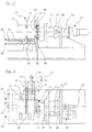
- Fig. 1 shows a plant part of a filling plant for Metal drums, so-called KEG drums.
- the empty ones Metal drums 10 are one by a feed conveyor 11 Barrel detection 12 supplied.
- metal barrels 10 recognized with dented collar 13 and then computer-controlled on a subsequent switch 14 one Transfer intermediate conveyor 15. Not damaged Metal drums 10 pass the switch 14 on a by-pass conveyor 16 directly to barrel cleaning and Bottling line.
- the metal drum 10 passes on the intermediate conveyor 15 a light barrier 17. This actuates a stopper 18, the possibly subsequent metal drums 10 stops.
- the Metal drum 10 then passes into a turning device 19.
- the metal drum 10 is in the turning device 19 tensioned, raised and then 90 ° with the damaged, bulging collar 13 forward filed again.
- the metal barrel then reaches one Roller conveyor 20, the metal barrel 10 in the Area of a holding device 21 transported. Here the metal barrel 10 is gripped by the holding device 21 and excited and then in more detail later descriptively bulged.
- the barrel After bulging the collar 13, the barrel is again from the holding device 21 on the roller conveyor 20 filed. Should the opposite collar 13 of the Metal barrel 10 damaged, the barrel will then rotated again by the turning device 19 by 180 ° and the denting process in the form described above fed. Are both collars 13 of a metal barrel 10 bulged, the barrel is turned by the turning device 19 90 ° in the upright position and by means of a Switch 22 to a second intermediate conveyor 23 postponed.
- the repaired metal barrel 10 passes here a second light barrier 24, which the stopper 18th actuated so that a new metal barrel 10 to be repaired is released.
- a further stopper may be provided, so that the intermediate conveyor 23, as well as the Intermediate conveyor 15 as a magazine for temporary storage of metal drums 10 can serve.
- the roller conveyor 20 is V-shaped in cross section educated. It consists of two rows 25, 26 in each case V-shaped rollers 27, 28. The metal barrel 10 is thereby always exactly in the middle fed.
- roller conveyor 20 is V-shaped in cross section is arranged in front of the turning device 19 Intermediate conveyor 15 and the intermediate conveyor 23 just are.
- the metal barrels 10 namely in the area of Intermediate conveyor 15 and 23 transported upright, while being transported by the roller conveyor 20 lying down become.
- they can also Intermediate conveyor 15 and / or 23 V-shaped if the metal drums 10 also in this area to be transported lying down.
- the holding device 21 has two below one another arranged pairs of gripper arms 29 and 30.
- This Gripping arms 29, 30 are articulated via hinge pins 31, 32 connected with holders 33 on the machine frame.
- the Gripping arms 29, 30 are non-rotatable with the hinge pin 31 or 32 connected.
- the hinge pins 31 and 32 are in turn rotatably supported in the holders 33.
- Between the two upper gripper arms 29 is a turning test with the upper pivot pin 31 connected actuating lever 34 arranged.
- This is at its free end with one Actuating cylinder 35, preferably one double-acting hydraulic cylinder, connected.
- the drive of the lower Gripping arms 30 in the opening and closing direction take place via a gear connection with the upper gripper arms 29.
- intermeshing gears 36, 37 provided that also rotatably on the hinge pin 31, 32 are stored.
- the actual bulging of the collar 13 takes place through a total of four rollers, namely two backup rollers 38, 39, a pressure roller 40 and a calibration roller 41.
- the four Rollers 38, 39, 40, 41 are each on one Roller guide 42 mounted and in the radial direction Roller guide 42 adjustable.
- the platen roller 40 is in Radially seen the inside of the collar 13 and the support rollers 38, 39 and the calibration roller 41 of the Assigned outside of the collar 13.
- rollers 38, 39 and Calibration roller 41 on the one hand and the pressure roller 40 on the other hand By delivering the support rollers 38, 39 and Calibration roller 41 on the one hand and the pressure roller 40 on the other hand, during the rotation of the lathe chuck 44 bumps in the collar 13 are gradually bulged out, the rollers 38..41 initially as radial straightening rollers Act. It only comes in the final phase of the delivery movement for the so-called three-roll bending through the support rolls 38, 39 and the pressure roller 40.
- the roundness of the collar 13 is determined by suitable means supervised. This can be optoelectical sensors or mechanical sensors that are used during the Denting process, in-process, the roundness of the collar 13 monitor. As soon as the collar 13 is round again the lathe chuck 44 stopped and the rollers 38..41 open. The metal barrel 10 is now in the mentioned way back on the roller conveyor 20 Opening of the gripper arms 29, 30 lowered and can Roller conveyor 20 are transported away. As before mentioned, the metal barrel 10 is optionally by the Turning device 19 rotated and the other collar 13 of the Metal barrel 10 can be dented.
- the Printing roller 40 is such by a recess 48 profiled that they behind a tubular ring 49 on Collar 13 engages.
- the collars are usually 13 namely not only radially inwards, but also in Seen axial direction of the metal barrel 10, bent. Out for this reason the pressure roller 40 is also axial slidably mounted on a journal 50.
- a Compression spring specifically a plate spring assembly 51, tensions the Pressure roller 40 in the desired position of the collar 13 or his ring 49 before. 8 shows the pressure roller 40 in this position where they are in their far right Position.
- the system should also Metal drums bulged 10 different diameters can be.
- the diameter of each Metal barrel 10 also detected and to a computer Control of the dent process reported. This can be due to particularly simple way of delivering the Gripping arms 29, 30 on a corresponding angle encoder of the gears 36 or 37 or by a displacement sensor on Actuation cylinder take place.
- About the corresponding Norms of the metal barrels 10 is then the respective one Radius of rotation of the foot and head collar of the metal barrel 10 known. Then the feed movement of the rollers 38..41 via an automatic adjustment 53.
- Adjustment 53 should be sufficient.
Landscapes
- Engineering & Computer Science (AREA)
- Mechanical Engineering (AREA)
- Specific Conveyance Elements (AREA)
- Rollers For Roller Conveyors For Transfer (AREA)
- Filling Or Discharging Of Gas Storage Vessels (AREA)
- Rolls And Other Rotary Bodies (AREA)
- Finish Polishing, Edge Sharpening, And Grinding By Specific Grinding Devices (AREA)
- Processing And Handling Of Plastics And Other Materials For Molding In General (AREA)
Applications Claiming Priority (2)
| Application Number | Priority Date | Filing Date | Title |
|---|---|---|---|
| DE19847930A DE19847930A1 (de) | 1998-10-19 | 1998-10-19 | Vorrichtung zum Ausbeulen von Kragen an Metallfässern |
| DE19847930 | 1998-10-19 |
Publications (3)
| Publication Number | Publication Date |
|---|---|
| EP0997205A2 true EP0997205A2 (fr) | 2000-05-03 |
| EP0997205A3 EP0997205A3 (fr) | 2002-01-30 |
| EP0997205B1 EP0997205B1 (fr) | 2004-09-01 |
Family
ID=7884805
Family Applications (1)
| Application Number | Title | Priority Date | Filing Date |
|---|---|---|---|
| EP99120604A Expired - Lifetime EP0997205B1 (fr) | 1998-10-19 | 1999-10-18 | Dispositif pour débosseler les collerettes de tonneaux métalliques |
Country Status (4)
| Country | Link |
|---|---|
| EP (1) | EP0997205B1 (fr) |
| AT (1) | ATE275008T1 (fr) |
| DE (2) | DE19847930A1 (fr) |
| ES (1) | ES2227948T3 (fr) |
Cited By (2)
| Publication number | Priority date | Publication date | Assignee | Title |
|---|---|---|---|---|
| CN112705591A (zh) * | 2020-11-23 | 2021-04-27 | 湖南兵器资江机器有限公司 | 一种筒形薄壁零件转圆装置 |
| CN118788793A (zh) * | 2024-09-03 | 2024-10-18 | 江苏铭丰电子材料科技有限公司 | 一种多层复合铜箔生产用表面压平装置 |
Families Citing this family (1)
| Publication number | Priority date | Publication date | Assignee | Title |
|---|---|---|---|---|
| WO2012088550A1 (fr) * | 2010-12-23 | 2012-06-28 | Gramany Kanniappen Verrsamy | Unité de réparation de cylindre |
Citations (2)
| Publication number | Priority date | Publication date | Assignee | Title |
|---|---|---|---|---|
| FR2542646A1 (fr) | 1983-03-14 | 1984-09-21 | Jacques Maxel | Machine a reformer les futs |
| EP0377219B1 (fr) | 1989-01-04 | 1993-03-03 | Dtm Drucklufttechnik Maschinenbau Gmbh | Dispositif pour faire des bosses dans les bords de tonneaux en métal |
Family Cites Families (5)
| Publication number | Priority date | Publication date | Assignee | Title |
|---|---|---|---|---|
| DE2119633B2 (de) * | 1971-04-22 | 1976-10-07 | Moeller & Neumann Gmbh, 6670 St Ingbert | Rollgang mit mehreren behandlungs- oder bearbeitungsstationen |
| DE2442093A1 (de) * | 1974-09-03 | 1976-03-18 | Schmitz Soehne Gmbh J H | Kugelrollgang fuer rundmaterialtransport und rundmaterial-drehung |
| US3941255A (en) * | 1974-11-25 | 1976-03-02 | Gulf & Western Manufacturing Company | Article turning device |
| DE3723521A1 (de) * | 1987-07-16 | 1989-01-26 | C A Neubecker Gmbh & Co Kg Mas | Vorrichtung zur drehung eines stueckgutes um seine achsen |
| IL100279A (en) * | 1991-12-08 | 1994-05-30 | Meir Kuzhik | Apparatus and method for repairing containers |
-
1998
- 1998-10-19 DE DE19847930A patent/DE19847930A1/de not_active Withdrawn
-
1999
- 1999-10-18 AT AT99120604T patent/ATE275008T1/de not_active IP Right Cessation
- 1999-10-18 ES ES99120604T patent/ES2227948T3/es not_active Expired - Lifetime
- 1999-10-18 DE DE59910384T patent/DE59910384D1/de not_active Expired - Fee Related
- 1999-10-18 EP EP99120604A patent/EP0997205B1/fr not_active Expired - Lifetime
Patent Citations (2)
| Publication number | Priority date | Publication date | Assignee | Title |
|---|---|---|---|---|
| FR2542646A1 (fr) | 1983-03-14 | 1984-09-21 | Jacques Maxel | Machine a reformer les futs |
| EP0377219B1 (fr) | 1989-01-04 | 1993-03-03 | Dtm Drucklufttechnik Maschinenbau Gmbh | Dispositif pour faire des bosses dans les bords de tonneaux en métal |
Cited By (2)
| Publication number | Priority date | Publication date | Assignee | Title |
|---|---|---|---|---|
| CN112705591A (zh) * | 2020-11-23 | 2021-04-27 | 湖南兵器资江机器有限公司 | 一种筒形薄壁零件转圆装置 |
| CN118788793A (zh) * | 2024-09-03 | 2024-10-18 | 江苏铭丰电子材料科技有限公司 | 一种多层复合铜箔生产用表面压平装置 |
Also Published As
| Publication number | Publication date |
|---|---|
| DE19847930A1 (de) | 2000-04-20 |
| EP0997205A3 (fr) | 2002-01-30 |
| ATE275008T1 (de) | 2004-09-15 |
| ES2227948T3 (es) | 2005-04-01 |
| EP0997205B1 (fr) | 2004-09-01 |
| DE59910384D1 (de) | 2004-10-07 |
Similar Documents
| Publication | Publication Date | Title |
|---|---|---|
| EP0611363B1 (fr) | Dispositif de changement de bobines | |
| DE2628254C2 (de) | Vorrichtung zur Behandlung von mit Öffnungen versehenen Gegenständen | |
| DE69216308T2 (de) | Warenbaumwechsler für eine Webmaschine | |
| DE102014222168A1 (de) | Verfahren und Vorrichtung zur Handhabung von auf Rollen aufgewickeltem Flach- und/oder Folienmaterial | |
| EP0145640A2 (fr) | Dispositif pour appliquer des étiquettes sur des récipients ronds | |
| CH617876A5 (fr) | ||
| EP0997205B1 (fr) | Dispositif pour débosseler les collerettes de tonneaux métalliques | |
| DE2602944C3 (de) | Maschine zum Herstellen von Behältern aus Glasrohren | |
| EP0881041A2 (fr) | Machine d'écrouissage pour vilbrequins | |
| EP2110353B1 (fr) | Dispositif destiné au traitement de bandes d'étiquettes | |
| DE911347C (de) | Vorrichtung zum Zufuehren gleichartiger, laengs uebereinandergeschichteter Werkstuecke, z.B. Bolzen | |
| DE2457859A1 (de) | Vorrichtung zum erfassen und freigeben von werkstuecken | |
| DE3422810A1 (de) | Schmiedepresse | |
| CH677655A5 (fr) | ||
| EP3600709B1 (fr) | Procédé de cintrage de découpes de tôle pour des unités d'emballage et machine à souder à cordon longitudinal pour la fabrication de corps de boîtes comprenant un poste de cintrage | |
| DE3717423C2 (fr) | ||
| EP2998258B1 (fr) | Dispositif d'enroulement de feuille pour une machine d'emballage | |
| EP4273077A1 (fr) | Dispositif de transport de récipients et procédé associé | |
| DE2836480B2 (de) | Vorrichtung zum Aufnehmen und Drehen eines Bandbundes | |
| EP0027106A1 (fr) | Dispositif pour amener automatiquement du matériau en tiges à une machine à cintrer des brides d'armature de béton | |
| DE2946719C2 (fr) | ||
| DE4411366B4 (de) | Verfahren zum Aufnehmen und Transportieren einer Rolle aus aufgewickeltem Streifenmaterial zwischen zwei Funktionsstationen | |
| DE3925987A1 (de) | Verfahren und vorrichtung zum drehen eines kopses, der aufrechtstehend auf dem aufsteckdorn einer palette aufgesteckt ist | |
| CH686832A5 (de) | Hubeinrichtung. | |
| CH685632A5 (de) | Transportfahrzeug für Wattewickel. |
Legal Events
| Date | Code | Title | Description |
|---|---|---|---|
| PUAI | Public reference made under article 153(3) epc to a published international application that has entered the european phase |
Free format text: ORIGINAL CODE: 0009012 |
|
| AK | Designated contracting states |
Kind code of ref document: A2 Designated state(s): AT BE CH CY DE DK ES FI FR GB GR IE IT LI LU MC NL PT SE |
|
| AX | Request for extension of the european patent |
Free format text: AL;LT;LV;MK;RO;SI |
|
| PUAL | Search report despatched |
Free format text: ORIGINAL CODE: 0009013 |
|
| AK | Designated contracting states |
Kind code of ref document: A3 Designated state(s): AT BE CH CY DE DK ES FI FR GB GR IE IT LI LU MC NL PT SE |
|
| AX | Request for extension of the european patent |
Free format text: AL;LT;LV;MK;RO;SI |
|
| 17P | Request for examination filed |
Effective date: 20020701 |
|
| AKX | Designation fees paid |
Free format text: AT BE CH CY DE DK ES FI FR GB GR IE IT LI LU MC NL PT SE |
|
| GRAP | Despatch of communication of intention to grant a patent |
Free format text: ORIGINAL CODE: EPIDOSNIGR1 |
|
| GRAS | Grant fee paid |
Free format text: ORIGINAL CODE: EPIDOSNIGR3 |
|
| GRAA | (expected) grant |
Free format text: ORIGINAL CODE: 0009210 |
|
| AK | Designated contracting states |
Kind code of ref document: B1 Designated state(s): AT BE CH CY DE DK ES FI FR GB GR IE IT LI LU MC NL PT SE |
|
| PG25 | Lapsed in a contracting state [announced via postgrant information from national office to epo] |
Ref country code: NL Free format text: LAPSE BECAUSE OF FAILURE TO SUBMIT A TRANSLATION OF THE DESCRIPTION OR TO PAY THE FEE WITHIN THE PRESCRIBED TIME-LIMIT Effective date: 20040901 Ref country code: IT Free format text: LAPSE BECAUSE OF FAILURE TO SUBMIT A TRANSLATION OF THE DESCRIPTION OR TO PAY THE FEE WITHIN THE PRE;WARNING: LAPSES OF ITALIAN PATENTS WITH EFFECTIVE DATE BEFORE 2007 MAY HAVE OCCURRED AT ANY TIME BEFORE 2007. THE CORRECT EFFECTIVE DATE MAY BE DIFFERENT FROM THE ONE RECORDED.SCRIBED TIME-LIMIT Effective date: 20040901 Ref country code: IE Free format text: LAPSE BECAUSE OF FAILURE TO SUBMIT A TRANSLATION OF THE DESCRIPTION OR TO PAY THE FEE WITHIN THE PRESCRIBED TIME-LIMIT Effective date: 20040901 Ref country code: FR Free format text: LAPSE BECAUSE OF FAILURE TO SUBMIT A TRANSLATION OF THE DESCRIPTION OR TO PAY THE FEE WITHIN THE PRESCRIBED TIME-LIMIT Effective date: 20040901 Ref country code: FI Free format text: LAPSE BECAUSE OF FAILURE TO SUBMIT A TRANSLATION OF THE DESCRIPTION OR TO PAY THE FEE WITHIN THE PRESCRIBED TIME-LIMIT Effective date: 20040901 Ref country code: CY Free format text: LAPSE BECAUSE OF FAILURE TO SUBMIT A TRANSLATION OF THE DESCRIPTION OR TO PAY THE FEE WITHIN THE PRESCRIBED TIME-LIMIT Effective date: 20040901 |
|
| REG | Reference to a national code |
Ref country code: GB Ref legal event code: FG4D Free format text: NOT ENGLISH |
|
| REG | Reference to a national code |
Ref country code: CH Ref legal event code: EP |
|
| REG | Reference to a national code |
Ref country code: IE Ref legal event code: FG4D Free format text: GERMAN |
|
| REF | Corresponds to: |
Ref document number: 59910384 Country of ref document: DE Date of ref document: 20041007 Kind code of ref document: P |
|
| PG25 | Lapsed in a contracting state [announced via postgrant information from national office to epo] |
Ref country code: LU Free format text: LAPSE BECAUSE OF NON-PAYMENT OF DUE FEES Effective date: 20041018 |
|
| PG25 | Lapsed in a contracting state [announced via postgrant information from national office to epo] |
Ref country code: MC Free format text: LAPSE BECAUSE OF NON-PAYMENT OF DUE FEES Effective date: 20041031 Ref country code: LI Free format text: LAPSE BECAUSE OF NON-PAYMENT OF DUE FEES Effective date: 20041031 Ref country code: CH Free format text: LAPSE BECAUSE OF NON-PAYMENT OF DUE FEES Effective date: 20041031 |
|
| PG25 | Lapsed in a contracting state [announced via postgrant information from national office to epo] |
Ref country code: SE Free format text: LAPSE BECAUSE OF FAILURE TO SUBMIT A TRANSLATION OF THE DESCRIPTION OR TO PAY THE FEE WITHIN THE PRESCRIBED TIME-LIMIT Effective date: 20041201 Ref country code: GR Free format text: LAPSE BECAUSE OF FAILURE TO SUBMIT A TRANSLATION OF THE DESCRIPTION OR TO PAY THE FEE WITHIN THE PRESCRIBED TIME-LIMIT Effective date: 20041201 Ref country code: DK Free format text: LAPSE BECAUSE OF FAILURE TO SUBMIT A TRANSLATION OF THE DESCRIPTION OR TO PAY THE FEE WITHIN THE PRESCRIBED TIME-LIMIT Effective date: 20041201 |
|
| GBT | Gb: translation of ep patent filed (gb section 77(6)(a)/1977) |
Effective date: 20041216 |
|
| NLV1 | Nl: lapsed or annulled due to failure to fulfill the requirements of art. 29p and 29m of the patents act | ||
| REG | Reference to a national code |
Ref country code: ES Ref legal event code: FG2A Ref document number: 2227948 Country of ref document: ES Kind code of ref document: T3 |
|
| REG | Reference to a national code |
Ref country code: IE Ref legal event code: FD4D |
|
| REG | Reference to a national code |
Ref country code: CH Ref legal event code: PL |
|
| PLBE | No opposition filed within time limit |
Free format text: ORIGINAL CODE: 0009261 |
|
| STAA | Information on the status of an ep patent application or granted ep patent |
Free format text: STATUS: NO OPPOSITION FILED WITHIN TIME LIMIT |
|
| 26N | No opposition filed |
Effective date: 20050602 |
|
| EN | Fr: translation not filed | ||
| PGFP | Annual fee paid to national office [announced via postgrant information from national office to epo] |
Ref country code: GB Payment date: 20051014 Year of fee payment: 7 |
|
| PGFP | Annual fee paid to national office [announced via postgrant information from national office to epo] |
Ref country code: BE Payment date: 20051024 Year of fee payment: 7 Ref country code: AT Payment date: 20051024 Year of fee payment: 7 |
|
| PGFP | Annual fee paid to national office [announced via postgrant information from national office to epo] |
Ref country code: DE Payment date: 20051031 Year of fee payment: 7 |
|
| PGFP | Annual fee paid to national office [announced via postgrant information from national office to epo] |
Ref country code: ES Payment date: 20051107 Year of fee payment: 7 |
|
| PG25 | Lapsed in a contracting state [announced via postgrant information from national office to epo] |
Ref country code: AT Free format text: LAPSE BECAUSE OF NON-PAYMENT OF DUE FEES Effective date: 20061018 |
|
| PG25 | Lapsed in a contracting state [announced via postgrant information from national office to epo] |
Ref country code: DE Free format text: LAPSE BECAUSE OF NON-PAYMENT OF DUE FEES Effective date: 20070501 |
|
| GBPC | Gb: european patent ceased through non-payment of renewal fee |
Effective date: 20061018 |
|
| PG25 | Lapsed in a contracting state [announced via postgrant information from national office to epo] |
Ref country code: GB Free format text: LAPSE BECAUSE OF NON-PAYMENT OF DUE FEES Effective date: 20061018 |
|
| BERE | Be: lapsed |
Owner name: THOMAS *ELLMERS G.M.B.H. Effective date: 20061031 |
|
| PG25 | Lapsed in a contracting state [announced via postgrant information from national office to epo] |
Ref country code: PT Free format text: LAPSE BECAUSE OF NON-PAYMENT OF DUE FEES Effective date: 20050201 |
|
| REG | Reference to a national code |
Ref country code: ES Ref legal event code: FD2A Effective date: 20061019 |
|
| PG25 | Lapsed in a contracting state [announced via postgrant information from national office to epo] |
Ref country code: ES Free format text: LAPSE BECAUSE OF NON-PAYMENT OF DUE FEES Effective date: 20061019 |
|
| PG25 | Lapsed in a contracting state [announced via postgrant information from national office to epo] |
Ref country code: BE Free format text: LAPSE BECAUSE OF FAILURE TO SUBMIT A TRANSLATION OF THE DESCRIPTION OR TO PAY THE FEE WITHIN THE PRESCRIBED TIME-LIMIT Effective date: 20061031 |