EP0997257A1 - Verfahren zum Steuern eines Bewegungsablaufs eines bewegbaren Bauteils einer Kunststoff-Spritzgiessmaschine - Google Patents
Verfahren zum Steuern eines Bewegungsablaufs eines bewegbaren Bauteils einer Kunststoff-Spritzgiessmaschine Download PDFInfo
- Publication number
- EP0997257A1 EP0997257A1 EP99118334A EP99118334A EP0997257A1 EP 0997257 A1 EP0997257 A1 EP 0997257A1 EP 99118334 A EP99118334 A EP 99118334A EP 99118334 A EP99118334 A EP 99118334A EP 0997257 A1 EP0997257 A1 EP 0997257A1
- Authority
- EP
- European Patent Office
- Prior art keywords
- time
- movable component
- movement
- measure
- movable
- Prior art date
- Legal status (The legal status is an assumption and is not a legal conclusion. Google has not performed a legal analysis and makes no representation as to the accuracy of the status listed.)
- Granted
Links
Images


Classifications
-
- G—PHYSICS
- G05—CONTROLLING; REGULATING
- G05B—CONTROL OR REGULATING SYSTEMS IN GENERAL; FUNCTIONAL ELEMENTS OF SUCH SYSTEMS; MONITORING OR TESTING ARRANGEMENTS FOR SUCH SYSTEMS OR ELEMENTS
- G05B19/00—Program-control systems
- G05B19/02—Program-control systems electric
- G05B19/18—Numerical control [NC], i.e. automatically operating machines, in particular machine tools, e.g. in a manufacturing environment, so as to execute positioning, movement or co-ordinated operations by means of program data in numerical form
- G05B19/182—Numerical control [NC], i.e. automatically operating machines, in particular machine tools, e.g. in a manufacturing environment, so as to execute positioning, movement or co-ordinated operations by means of program data in numerical form characterised by the machine tool function, e.g. thread cutting, cam making, tool direction control
-
- B—PERFORMING OPERATIONS; TRANSPORTING
- B23—MACHINE TOOLS; METAL-WORKING NOT OTHERWISE PROVIDED FOR
- B23Q—DETAILS, COMPONENTS, OR ACCESSORIES FOR MACHINE TOOLS, e.g. ARRANGEMENTS FOR COPYING OR CONTROLLING; MACHINE TOOLS IN GENERAL CHARACTERISED BY THE CONSTRUCTION OF PARTICULAR DETAILS OR COMPONENTS; COMBINATIONS OR ASSOCIATIONS OF METAL-WORKING MACHINES, NOT DIRECTED TO A PARTICULAR RESULT
- B23Q1/00—Members which are comprised in the general build-up of a form of machine, particularly relatively large fixed members
- B23Q1/25—Movable or adjustable work or tool supports
- B23Q1/26—Movable or adjustable work or tool supports characterised by constructional features relating to the co-operation of relatively movable members; Means for preventing relative movement of such members
-
- B—PERFORMING OPERATIONS; TRANSPORTING
- B23—MACHINE TOOLS; METAL-WORKING NOT OTHERWISE PROVIDED FOR
- B23Q—DETAILS, COMPONENTS, OR ACCESSORIES FOR MACHINE TOOLS, e.g. ARRANGEMENTS FOR COPYING OR CONTROLLING; MACHINE TOOLS IN GENERAL CHARACTERISED BY THE CONSTRUCTION OF PARTICULAR DETAILS OR COMPONENTS; COMBINATIONS OR ASSOCIATIONS OF METAL-WORKING MACHINES, NOT DIRECTED TO A PARTICULAR RESULT
- B23Q16/00—Equipment for precise positioning of tool or work into particular locations not otherwise provided for
- B23Q16/008—Cushioning the abutting movement
-
- B—PERFORMING OPERATIONS; TRANSPORTING
- B23—MACHINE TOOLS; METAL-WORKING NOT OTHERWISE PROVIDED FOR
- B23Q—DETAILS, COMPONENTS, OR ACCESSORIES FOR MACHINE TOOLS, e.g. ARRANGEMENTS FOR COPYING OR CONTROLLING; MACHINE TOOLS IN GENERAL CHARACTERISED BY THE CONSTRUCTION OF PARTICULAR DETAILS OR COMPONENTS; COMBINATIONS OR ASSOCIATIONS OF METAL-WORKING MACHINES, NOT DIRECTED TO A PARTICULAR RESULT
- B23Q5/00—Driving or feeding mechanisms; Control arrangements therefor
- B23Q5/54—Arrangements or details not restricted to group B23Q5/02 or group B23Q5/22 respectively, e.g. control handles
- B23Q5/58—Safety devices
-
- B—PERFORMING OPERATIONS; TRANSPORTING
- B29—WORKING OF PLASTICS; WORKING OF SUBSTANCES IN A PLASTIC STATE IN GENERAL
- B29C—SHAPING OR JOINING OF PLASTICS; SHAPING OF MATERIAL IN A PLASTIC STATE, NOT OTHERWISE PROVIDED FOR; AFTER-TREATMENT OF THE SHAPED PRODUCTS, e.g. REPAIRING
- B29C45/00—Injection moulding, i.e. forcing the required volume of moulding material through a nozzle into a closed mould; Apparatus therefor
- B29C45/14—Injection moulding, i.e. forcing the required volume of moulding material through a nozzle into a closed mould; Apparatus therefor incorporating preformed parts or layers, e.g. injection moulding around inserts or for coating articles
- B29C45/14008—Inserting articles into the mould
-
- B—PERFORMING OPERATIONS; TRANSPORTING
- B29—WORKING OF PLASTICS; WORKING OF SUBSTANCES IN A PLASTIC STATE IN GENERAL
- B29C—SHAPING OR JOINING OF PLASTICS; SHAPING OF MATERIAL IN A PLASTIC STATE, NOT OTHERWISE PROVIDED FOR; AFTER-TREATMENT OF THE SHAPED PRODUCTS, e.g. REPAIRING
- B29C45/00—Injection moulding, i.e. forcing the required volume of moulding material through a nozzle into a closed mould; Apparatus therefor
- B29C45/17—Component parts, details or accessories; Auxiliary operations
- B29C45/40—Removing or ejecting moulded articles
- B29C45/42—Removing or ejecting moulded articles using means movable from outside the mould between mould parts, e.g. robots
-
- B—PERFORMING OPERATIONS; TRANSPORTING
- B29—WORKING OF PLASTICS; WORKING OF SUBSTANCES IN A PLASTIC STATE IN GENERAL
- B29C—SHAPING OR JOINING OF PLASTICS; SHAPING OF MATERIAL IN A PLASTIC STATE, NOT OTHERWISE PROVIDED FOR; AFTER-TREATMENT OF THE SHAPED PRODUCTS, e.g. REPAIRING
- B29C45/00—Injection moulding, i.e. forcing the required volume of moulding material through a nozzle into a closed mould; Apparatus therefor
- B29C45/17—Component parts, details or accessories; Auxiliary operations
- B29C45/76—Measuring, controlling or regulating
- B29C45/7626—Measuring, controlling or regulating the ejection or removal of moulded articles
-
- F—MECHANICAL ENGINEERING; LIGHTING; HEATING; WEAPONS; BLASTING
- F16—ENGINEERING ELEMENTS AND UNITS; GENERAL MEASURES FOR PRODUCING AND MAINTAINING EFFECTIVE FUNCTIONING OF MACHINES OR INSTALLATIONS; THERMAL INSULATION IN GENERAL
- F16C—SHAFTS; FLEXIBLE SHAFTS; ELEMENTS OR CRANKSHAFT MECHANISMS; ROTARY BODIES OTHER THAN GEARING ELEMENTS; BEARINGS
- F16C29/00—Bearings for parts moving only linearly
- F16C29/02—Sliding-contact bearings
-
- F—MECHANICAL ENGINEERING; LIGHTING; HEATING; WEAPONS; BLASTING
- F16—ENGINEERING ELEMENTS AND UNITS; GENERAL MEASURES FOR PRODUCING AND MAINTAINING EFFECTIVE FUNCTIONING OF MACHINES OR INSTALLATIONS; THERMAL INSULATION IN GENERAL
- F16F—SPRINGS; SHOCK-ABSORBERS; MEANS FOR DAMPING VIBRATION
- F16F7/00—Vibration-dampers; Shock-absorbers
- F16F7/12—Vibration-dampers; Shock-absorbers using plastic deformation of members
-
- G—PHYSICS
- G05—CONTROLLING; REGULATING
- G05B—CONTROL OR REGULATING SYSTEMS IN GENERAL; FUNCTIONAL ELEMENTS OF SUCH SYSTEMS; MONITORING OR TESTING ARRANGEMENTS FOR SUCH SYSTEMS OR ELEMENTS
- G05B19/00—Program-control systems
- G05B19/02—Program-control systems electric
- G05B19/18—Numerical control [NC], i.e. automatically operating machines, in particular machine tools, e.g. in a manufacturing environment, so as to execute positioning, movement or co-ordinated operations by means of program data in numerical form
- G05B19/416—Numerical control [NC], i.e. automatically operating machines, in particular machine tools, e.g. in a manufacturing environment, so as to execute positioning, movement or co-ordinated operations by means of program data in numerical form characterised by control of velocity, acceleration or deceleration
-
- B—PERFORMING OPERATIONS; TRANSPORTING
- B29—WORKING OF PLASTICS; WORKING OF SUBSTANCES IN A PLASTIC STATE IN GENERAL
- B29C—SHAPING OR JOINING OF PLASTICS; SHAPING OF MATERIAL IN A PLASTIC STATE, NOT OTHERWISE PROVIDED FOR; AFTER-TREATMENT OF THE SHAPED PRODUCTS, e.g. REPAIRING
- B29C45/00—Injection moulding, i.e. forcing the required volume of moulding material through a nozzle into a closed mould; Apparatus therefor
- B29C45/17—Component parts, details or accessories; Auxiliary operations
- B29C45/76—Measuring, controlling or regulating
- B29C45/7626—Measuring, controlling or regulating the ejection or removal of moulded articles
- B29C2045/7633—Take out or gripping means
-
- B—PERFORMING OPERATIONS; TRANSPORTING
- B29—WORKING OF PLASTICS; WORKING OF SUBSTANCES IN A PLASTIC STATE IN GENERAL
- B29C—SHAPING OR JOINING OF PLASTICS; SHAPING OF MATERIAL IN A PLASTIC STATE, NOT OTHERWISE PROVIDED FOR; AFTER-TREATMENT OF THE SHAPED PRODUCTS, e.g. REPAIRING
- B29C2945/00—Indexing scheme relating to injection moulding, i.e. forcing the required volume of moulding material through a nozzle into a closed mould
- B29C2945/76—Measuring, controlling or regulating
- B29C2945/76003—Measured parameter
- B29C2945/76066—Time
- B29C2945/76076—Time duration
-
- B—PERFORMING OPERATIONS; TRANSPORTING
- B29—WORKING OF PLASTICS; WORKING OF SUBSTANCES IN A PLASTIC STATE IN GENERAL
- B29C—SHAPING OR JOINING OF PLASTICS; SHAPING OF MATERIAL IN A PLASTIC STATE, NOT OTHERWISE PROVIDED FOR; AFTER-TREATMENT OF THE SHAPED PRODUCTS, e.g. REPAIRING
- B29C2945/00—Indexing scheme relating to injection moulding, i.e. forcing the required volume of moulding material through a nozzle into a closed mould
- B29C2945/76—Measuring, controlling or regulating
- B29C2945/76177—Location of measurement
- B29C2945/76254—Mould
- B29C2945/76257—Mould cavity
- B29C2945/7626—Mould cavity cavity walls
- B29C2945/76264—Mould cavity cavity walls movable
-
- B—PERFORMING OPERATIONS; TRANSPORTING
- B29—WORKING OF PLASTICS; WORKING OF SUBSTANCES IN A PLASTIC STATE IN GENERAL
- B29C—SHAPING OR JOINING OF PLASTICS; SHAPING OF MATERIAL IN A PLASTIC STATE, NOT OTHERWISE PROVIDED FOR; AFTER-TREATMENT OF THE SHAPED PRODUCTS, e.g. REPAIRING
- B29C2945/00—Indexing scheme relating to injection moulding, i.e. forcing the required volume of moulding material through a nozzle into a closed mould
- B29C2945/76—Measuring, controlling or regulating
- B29C2945/76494—Controlled parameter
- B29C2945/76595—Velocity
-
- B—PERFORMING OPERATIONS; TRANSPORTING
- B29—WORKING OF PLASTICS; WORKING OF SUBSTANCES IN A PLASTIC STATE IN GENERAL
- B29C—SHAPING OR JOINING OF PLASTICS; SHAPING OF MATERIAL IN A PLASTIC STATE, NOT OTHERWISE PROVIDED FOR; AFTER-TREATMENT OF THE SHAPED PRODUCTS, e.g. REPAIRING
- B29C2945/00—Indexing scheme relating to injection moulding, i.e. forcing the required volume of moulding material through a nozzle into a closed mould
- B29C2945/76—Measuring, controlling or regulating
- B29C2945/76494—Controlled parameter
- B29C2945/76648—Sequence, e.g. the order in which operations are conducted
-
- B—PERFORMING OPERATIONS; TRANSPORTING
- B29—WORKING OF PLASTICS; WORKING OF SUBSTANCES IN A PLASTIC STATE IN GENERAL
- B29C—SHAPING OR JOINING OF PLASTICS; SHAPING OF MATERIAL IN A PLASTIC STATE, NOT OTHERWISE PROVIDED FOR; AFTER-TREATMENT OF THE SHAPED PRODUCTS, e.g. REPAIRING
- B29C2945/00—Indexing scheme relating to injection moulding, i.e. forcing the required volume of moulding material through a nozzle into a closed mould
- B29C2945/76—Measuring, controlling or regulating
- B29C2945/76655—Location of control
- B29C2945/76732—Mould
- B29C2945/76735—Mould cavity
- B29C2945/76739—Mould cavity cavity walls
- B29C2945/76742—Mould cavity cavity walls movable
-
- B—PERFORMING OPERATIONS; TRANSPORTING
- B29—WORKING OF PLASTICS; WORKING OF SUBSTANCES IN A PLASTIC STATE IN GENERAL
- B29C—SHAPING OR JOINING OF PLASTICS; SHAPING OF MATERIAL IN A PLASTIC STATE, NOT OTHERWISE PROVIDED FOR; AFTER-TREATMENT OF THE SHAPED PRODUCTS, e.g. REPAIRING
- B29C2945/00—Indexing scheme relating to injection moulding, i.e. forcing the required volume of moulding material through a nozzle into a closed mould
- B29C2945/76—Measuring, controlling or regulating
- B29C2945/76929—Controlling method
- B29C2945/76939—Using stored or historical data sets
- B29C2945/76943—Using stored or historical data sets compare with thresholds
-
- F—MECHANICAL ENGINEERING; LIGHTING; HEATING; WEAPONS; BLASTING
- F16—ENGINEERING ELEMENTS AND UNITS; GENERAL MEASURES FOR PRODUCING AND MAINTAINING EFFECTIVE FUNCTIONING OF MACHINES OR INSTALLATIONS; THERMAL INSULATION IN GENERAL
- F16C—SHAFTS; FLEXIBLE SHAFTS; ELEMENTS OR CRANKSHAFT MECHANISMS; ROTARY BODIES OTHER THAN GEARING ELEMENTS; BEARINGS
- F16C2322/00—Apparatus used in shaping articles
- F16C2322/39—General buildup of machine tools, e.g. spindles, slides, actuators
-
- G—PHYSICS
- G05—CONTROLLING; REGULATING
- G05B—CONTROL OR REGULATING SYSTEMS IN GENERAL; FUNCTIONAL ELEMENTS OF SUCH SYSTEMS; MONITORING OR TESTING ARRANGEMENTS FOR SUCH SYSTEMS OR ELEMENTS
- G05B2219/00—Program-control systems
- G05B2219/30—Nc systems
- G05B2219/45—Nc applications
- G05B2219/45244—Injection molding
-
- G—PHYSICS
- G05—CONTROLLING; REGULATING
- G05B—CONTROL OR REGULATING SYSTEMS IN GENERAL; FUNCTIONAL ELEMENTS OF SUCH SYSTEMS; MONITORING OR TESTING ARRANGEMENTS FOR SUCH SYSTEMS OR ELEMENTS
- G05B2219/00—Program-control systems
- G05B2219/30—Nc systems
- G05B2219/50—Machine tool, machine tool null till machine tool work handling
- G05B2219/50234—Synchronize two spindles, axis, electronic transmission, line shafting
Definitions
- the present invention relates to a method for control a movement sequence of a first movable component Plastic injection molding machine, its trajectory from the trajectory a second movable component of the plastic injection molding machine is at least partially overlapped, whereby the movement of the first movable component depending on a representing a state of motion of the second movable component Release signal is started and at least a measure of time is determined.
- the invention also relates to a plastic injection molding machine with a first and a second movable component, whose trajectories overlap at least partially with a control unit for generating an enable signal for the Movement of the first movable component depending on a State of movement of the second movable component and by means to determine at least one measure of time.
- the injection mold belongs to a plastic injection molding machine and has at least one movable mold open and close can.
- the handling device sometimes called a robot, has a gripping tool that can be used, for example, to remove a manufactured tool Workpiece between at least two, in which case then open molds can be retracted and extended.
- a gripping tool that can be used, for example, to remove a manufactured tool Workpiece between at least two, in which case then open molds can be retracted and extended.
- the gripping tool is part of the plastic injection molding machine itself is.
- the safest way to achieve the latter is to start the movements of each of the two tools only if the second tool the trajectory of each first left.
- this has the disadvantage that due to the resulting dead times are the cycle time of the machine is very large.
- the cycle time is the time that the plastic injection molding machine for a complete work cycle needed by the time they get back ready to manufacture the next workpiece.
- the measurement of the time interval that the second tool is used to Traversing the route between the two sensors assigned to it provides a guarantee that the release signal is only generated if the second tool is with a speed corresponding to normal operation at a certain position moves.
- due to Mass inertia can be assumed that the second tool at least one in the event of a fault Distance traveled that there is no collision.
- the worst case that can occur is that the Drive of the second tool fails at the moment when the release signal for the first tool is generated. In this Fall, the first tool starts moving, while the second tool is the trajectory of the first tool not at the speed specified in normal operation can leave.
- this task becomes solved in that a first measure of time and a second Time measure determined and compared with each other, the first time measure the time span between the time of generation of the release signal and the time at which the first movable component the movement path of the second movable component reached, and the second measure of time between the time of generation of the release signal and indicates the time at which the second movable component Leaves trajectory of the first movable member, and that the sequence of movements of the first movable component in dependence is controlled by the comparison of the two times, that the difference of the second measure of time and the first measure of time is less than a predetermined, minimum tolerance value.
- the plastic injection molding machine according to the invention is thereby characterized in that a first measure of time is a period between the time of generation of the release signal and the time indicates to which the first movable component the movement path reached the second movable member, and that a second measure of time between the time of generation of the release signal and the time at which the second movable component the movement path of the first movable Component leaves, and that further the control unit Has means to the difference of the first time measure and the second time measure and depending on the difference to generate the release signal.
- the inventor of the present invention has recognized that the problem described at the outset is very good in the form of a lets formulate temporal relationship. He also recognized that such a wording goes very well with that the optimization of the cycle time of the injection molding machine also a problem in a temporal dimension is. By the inventor now the two mentioned in the task Formulated conditions in the same physical dimension has it been possible for him to introduce an optimization regulation in one common condition. Based on this knowledge can be a simple and optimal Achieve control of the motion sequences of the movable components.
- the tolerance value by which the second measure of time is always smaller indicates how much temporal reserve between the movements of the two tools is still present even in the event of a malfunction. On the other hand this value is a measure of how much additional dead time in the cycle time is available. The closer the tolerance value is to zero lies, the more optimal the procedure is with regard to the cycle time.
- the comparison of the two times mentioned can, for example, thereby done that this in a corresponding control unit of the Plastic injection molding machine according to the invention by software to be related to each other.
- the comparison also take place in that over corresponding Sensors hardware the difference between the two Time is determined and only then this difference on their Amount and its sign are evaluated.
- all other options are also available for determination and evaluation of a time difference within the scope of the present invention applicable. Which of these alternatives whichever is cheaper depends on the design conditions a corresponding plastic injection molding machine from.
- the two times to be compared are determined once after the first or every new start-up of the Machine. Alternatively, it can also be repeated in work mode become.
- Timekeeping means any size that is appropriate is to represent a time. For this it is not necessary that this size is actually in a unit such as Seconds or fractions of a second is determined. You can also the measures of time also a dimensionless number of consecutive times following identical or unequal impulses.
- the advantage of the method according to the invention is that with it a collision of the tools even in the event of a malfunction is prevented at the worst time while at the same time the cycle time of the machine taking this condition into account is optimally short.
- the method has the advantage that it is without major constructive Effort on a plastic injection molding machine according to the invention is to be realized. Accordingly, the achievable Advantage compared to no significant additional costs.
- Another advantage of the invention is that the optimal Trigger time for the generation of the release signal very much can be set quickly and precisely.
- the trigger time can also be set purely by machine.
- one of the moveable ones Components a mold that is relative to another mold can perform an opening and closing movement
- the other of the movable components is a gripping tool that is retractable and extendable between the molds.
- At least one of the time measures determined by means of a sensor.
- This measure has the advantage that it is at least one specific one Changes in time in the movement of the corresponding Component, for example due to temperature changes or aging processes.
- This measure has the advantage that it reduces the hardware effort and thus also the cost of an inventive Plastic injection molding machine can be reduced.
- the said Measure is possible due to the fact that not all Parameters in the motion sequences of a plastic injection molding machine such significant or rapid changes subject to a repeated, each updated Require measurement using a sensor.
- This measure is based on the fact that the gripping tool a plastic injection molding machine usually lighter is as that or the movable molds. Accordingly the dynamic behavior of the gripping tool is easier, influence easier and faster. Subject at the same time however, its movements are stronger and faster Changes in the operation of a machine.
- the measure mentioned thus has the advantage that the measure of time that is subject to stronger and shorter-term fluctuations currently recorded operating parameters is determined.
- the other measure of time is representative of the movement of the mold.
- the measures mentioned above offer the advantage on the one hand the effort and thus the costs of a plastic injection molding machine for the method according to the invention minimize and on the other hand at the same time for an optimal Operational control.
- the measures mentioned are also particularly advantageous in the event that the gripping tool is not part of an inventive Plastic injection molding machine, but as part of one separate handling device to be adapted to such got to. In this case, decreases due to the measures mentioned the application effort because in the control of the injection molding machine not about what was previously absolutely necessary Measure needs to be intervened.
- At least one of the times based on a change in acceleration, a distance and / or a dead time of at least one movable component set.
- This measure has the advantage that a setting this parameter the movement sequences of the movable components can be coordinated easily and reliably.
- the measure is particularly advantageous if the Changing the sizes mentioned, the measure of time and thus the sequence of movements the gripping tool of a plastic injection molding machine is set because this is due to its lower weight allows greater flexibility.
- the release signal generated when the second movable member a predetermined Trigger position is reached and the trigger position is set depending on the first and second time measure.
- This measure has the advantage that it is particularly simple Control enables that solely by changing the Control software changes the movements of the movable Components enabled.
- the trigger position for the generation of the release signal depending on the comparison of the two time measures, possibly iteratively, in the direction of one earlier trip postponed to the difference in time measures to the desired value. The earlier in the sequence of movements of the second movable component, the release signal for the first movable component is generated, the sooner it is reached the first movable component the movement path of the second movable Component.
- the second Time measure determined based on a simulation in which a failure a drive of the second movable component at the time of Generation of the release signal is simulated.
- This measure has the advantage that it is the second measure of time is determined by measurement in the event of a fault, the practically the worst case, i.e. corresponds to the worst case. Accordingly, all individual machine tolerances detected in this determination of the second measure of time. A collision of the movable components is therefore under reliably avoided in all conceivable circumstances. On the other hand the second measure of time is very easy for determine the worst possible case.
- This measure has the advantage that it is the first Time measure for the relevant case of a drive failure of the second movable component is extended or that even a prevents the first movable component from moving becomes.
- the latter case is only possible if the error signal is available so early that the movement of the first movable component, taking into account signal run times and switching times, can actually still be prevented can.
- the error signal is only at one point in time on which the first movable component already has its release signal has received, its movement can be based on the Signal run times and switching times are usually no longer complete prevent. In such a case, however, the movement of the first movable component is delayed, the lengthened Time until this the movement path of the second movable component reached.
- This measure has the same advantages as the aforementioned Measure. It is particularly beneficial in addition to the measure mentioned above, because with its help also malfunctions taken into account in the movement sequence of the second movable component that are not due to a drive failure are.
- the tolerance band before operating the injection molding machine under production conditions by running through the movement several times determined empirically.
- This measure has the advantage that the tolerance band changes in the actual movements of the moveable Components is adjusted. This makes it possible to change the width of the tolerance band to choose very small, which causes interference in Operating sequence of the second movable component recognized earlier become.
- this is Tolerance band under production conditions in predetermined Time intervals measured and readjusted accordingly.
- This measure has the advantage that the tolerance band too Changes in the motion sequences in the operation of the plastic injection molding machine is adjusted. This can be done again a reduction in the width of the tolerance band and thus associated early detection of malfunctions.
- This measure also has the advantage of making changes in the motion sequences of the movable components, for example of temperature changes, are always taken into account.
- a supply voltage for driving the second movable component with a storage medium so buffered that the drive of the second movable component even in the event of failure the supply voltage is maintained until the second movable component the path of movement of the first movable Component has left.
- This measure has the advantage that the second Time is shortened because the movement of the second movable Component for one even if the supply voltage fails certain period of time is maintained. Usually lies this time span of the order of 300 ms.
- the reduction of the second measure of time enables the first measure of time smaller, which reduces the cycle time of the plastic injection molding machine overall also gets shorter.
- the buffering the supply voltage is preferred by an increase the capacitance in the so-called intermediate circuit, that is a rectifier circuit part for smoothing an alternating mains voltage, reached.
- the failure of the power supply for driving a movable Component is in generic plastic injection molding machines one of the most common causes of errors. root cause For example, electromagnetic interference in the environment of the Be injection molding machine.
- the first movable component in the event of a fault in the Sequence of movements of the second movable component with maximum Deceleration braked.
- the Measure gains its importance from the fact that the movable Components are normally delayed in a controlled manner. This regulation must therefore be switched off or overridden.
- the Measure has the advantage that the first measure of time is dynamically increased in the event of a malfunction. Hereby it is possible to measure the first time in trouble-free operation smaller, which in turn reduces the cycle time of the Machine is shortened. Because of the dynamic enlargement of the first measure of time in the event of a malfunction is ensured at the same time, that a collision of the movable components avoided becomes.
- the first movable component in trouble-free operation with a first Brake fluid braked and it will help in the event of a fault an additional brake means with one compared to the work operation decelerated with greater deceleration.
- the actuator can be acted on directly for braking.
- an external brake for example a shoe brake.
- a bumper can be used, in which kinetic energy is converted into deformation.
- Such Bumpers are e.g. trained as baffle pots and stand available as standard parts in automotive engineering.
- This measure has the advantage that a higher one maximum braking force can be applied than this in trouble-free Injection molding machine operation required is. Due to the increased braking force in the event of a malfunction, as previously stated, the first measure of time dynamically increased. In a further advantageous embodiment of this measure the regulation of the deceleration of the first movable component is switched off, to prevent this regulation of production counteracts a maximum braking force. This ensures that the first measure of time in the event of a malfunction a maximum possible dimension is expanded. The hereby achieved Gain in temporal security reserve is advantageous in trouble-free operation of the injection molding machine taken into account to reduce the cycle time.
- the method according to the invention becomes the first movable component after receiving the release signal initially accelerated with less acceleration and it becomes collision-free after passing a last possible Stopping point at least until entry into the Path of movement of the second movable component with maximum acceleration accelerates.
- This measure ensures that the critical area, within which the first movable component is no longer be stopped in time to prevent a collision can be shortened as much as possible. As long as the first movable Component the last possible collision-free stopping point has not yet happened, it can happen if a malfunction occurs in the movement sequence of the second movable component be stopped before entering its trajectory. This makes a collision independent of the position of the second movable component reliably avoided.
- the first movable component After passing the last possible collision-free stopping point However, the first movable component can no longer be used Entry into the movement path of the second movable component be stopped.
- the worst possible case for the occurrence a malfunction in the drive of the second movable component is therefore the moment when the first movable component last possible collision-free stopping point.
- the disturbance occurring before this time becomes the first movable component due to the emergency stop signal generated in this case stopped in time.
- the time at which the disturbance occurred was the second movable one Component, on the other hand, already further out of the path of movement of the first movable component removed.
- the measure above has the advantage that the period between generation the release signal and passing the last possible collision-free stopping point extended as far as possible will, during the period after passing the last possible Stopping point is shortened as much as possible.
- the on this Wise shortened critical time enables cycle times to shorten the injection molding machine in trouble-free operation.
- the time period since passing the last possible collision-free Stop point used to control the motion sequences.
- the movement path of one of the movable components runs approximately vertically, this movable component from above in retracts the path of movement of the other movable component, and in the event of a malfunction, the first named component is marked with a Holding means secured against falling.
- This measure is particularly important if through the failure of the supply voltage is the vertical retraction from above Component loses its fixation against gravity.
- the measure thus has the advantage that even under a collision of the two movable components is reliably prevented.
- a common control unit for Both movable components can be provided in which the movement sequences both components are compared directly and in In the event of a malfunction an interference signal is generated.
- This measure has the advantage that as a result of the comparison effected synchronization of the movements in the case a malfunction can be remedied as quickly as possible can, e.g. an emergency stop or shutdown triggered becomes. The dead times that occur are this way minimized.
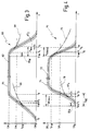
- 1 and 2 is a plastic injection molding machine according to the invention in its entirety with the reference number 10 designated.
- the plastic injection molding machine 10 has a first movable one Component, which here consists of a movable mold 12 and a fixed mold 14 there.
- This Embodiment has been chosen to simplify the illustration and includes other embodiments with multiple moveable Mold tools, especially stack tools not out.
- Reference number 16 denotes a second movable component, namely a gripping tool, as shown in FIG. 2 for removing a workpiece 18 from a cavity 20 of the mold 14 in an area between the molds 12 and 14 is retractable.
- the reference numeral 22 in Fig. 2 is the path of movement of the movable Mold tool 12 designated by the lines 24th and 26 is limited.
- the movement path 22 of the molding tool 12 is partially affected by the movement path 28 of the gripping tool 16 overlaps, which are indicated in FIG. 2 by means of lines 30 and 32 is.
- the representation of the movement path 28 of the gripping tool 16 is only to be understood here as an example, since its linear inward and outward movement further movements, that are required to remove the workpiece 18 overlap can.
- Reference number 34 denotes a control unit to which the signals of a sensor 36 and an optionally provided sensor 38, which is indicated only by dashed lines, are supplied.
- the sensor 36 is arranged at a position SR 1 , which corresponds to the position at which the gripping tool 16 reaches or leaves the movement path 22 of the molding tool 12.
- the optionally provided sensor 38 is arranged at a position SW 1 , which corresponds to the position at which the molding tool 12 reaches or leaves the movement path 28 of the gripping tool 16.
- the sensor 36 is suitable for incrementally reading markings 40 which are attached to the gripping tool 16, from which the control unit 34 can determine the current position of the gripping tool 16 and its speed. Sensor 38 is also designed accordingly.
- control signal 42 is one Drive unit 43 of the movable mold 12 and a Control signal 44 of a drive unit 45 of the gripping tool 16 fed.
- control signals 42 and 44 include on the one hand release signals for the movement of the respective Tool and on the other hand emergency stop signals.
- the drive units 43 and 45 each require a supply voltage, which is designated U VW in the case of the drive unit 43 and U VR in the case of the drive unit 45.
- U VW and U VR are usually direct voltages which are generated by rectifying an alternating mains voltage U N. This usually happens in the so-called intermediate circuit.
- the respective intermediate circuits contain additional or increased in capacity storage means 46 and 48.
- the storage means 46 and 48 serve to buffer the supply voltages U VW and U VR , so that the movement of the respective tools even in the event of failure to be able to maintain the supply voltage for at least a certain period of time. In the plastic injection molding machine shown here, this time period is in the order of magnitude of 300 ms.
- a further control signal 50 an additional brake means 51 and another Control signal 52 fed to an additional braking means 53.
- the additional braking means 51 acts on the molding tool 12 and serves this if there is a disturbance in the movement of the gripping tool 16 with maximum deceleration.
- the additional braking means 53 serves to the gripping tool 16 in the event of a malfunction in the movement sequence of the mold 12 to brake with maximum deceleration.
- the Additional brake means 51 and 53 are used in the plastic injection molding machine 10 in addition to the braking effect of each Drive units 43 and 45 used one each to achieve maximum delay.
- the additional control signal 52 and the additional braking means 53 are for the sake of Clarity only shown in FIG. 1.
- the gripping tool 16 begins its movement in the direction of the arrow 55.
- the release signal 44 required for this is generated at the time when the molding tool 12 passes the trigger position S FR in the direction of the arrow 56.
- FIG. 2 The reverse case is shown in FIG. 2, in which the molding tool 12 starts to move in the direction of the arrow 57 as soon as it receives a release signal 42. This is generated when the gripping tool 16 passes the trigger position S FW in the direction of the arrow 58.
- the arrow 59 indicates that the triggering position S FW can be changed by software within the control unit 34 in order to change the triggering time for the generation of the release signal 42.
- the movement sequence of the molding tool 12 is stored here completely as a parameter in the control unit 34, and the movement sequence of the gripping tool 16 is controlled as a function of the parameter data by changing the acceleration of the trigger point S FW and / or the dead times of the gripping tool 16.
- control unit 34 receives error signals F W and F R from monitoring circuits, not shown here, which are generated when a fault in the movement sequence of the respective tool 12 and 16 is determined.
- a possible source for generating these error signals are voltage monitoring circuits which monitor the supply voltages U VW and U VR .
- a path-time diagram for the movement of the movable mold 12 is designated in its entirety with the reference number 60.
- curve 62 Starting from position SW 0 , curve 62 initially rises monotonically to position SW 2 . This first part of the curve 62 describes the opening movement of the molding tool 12. Subsequently, the curve 62, starting from the position SW 2, initially runs constantly horizontally and then falls monotonically back to the position SW 0 . This sloping rear part of the curve 62 describes the closing movement of the molding tool 12.
- the reference number 64 denotes a tolerance band, within whose the curve 62 in a trouble-free operation of the Mold 12 runs. Leaving the tolerance band 64 means that there is a disturbance in the movement of the mold 12 is present. Such a case is indicated with the course 66.
- the course 68 describes a sequence of movements in which the movable mold 12 due to a malfunction in the drive of the Gripping tool 16 receives an emergency stop signal and accordingly is braked.
- a path-time diagram for describing the movement sequence of the gripping tool 16 in its entirety is designated by the reference number 70.
- curve 72 Starting from a position SR 0 , curve 72 initially increases monotonously up to a position SR 2 . This first part of curve 72 describes the retracting movement of gripping tool 16 between forming tools 12 and 14. Subsequently, curve 72, starting from position SR 2, initially runs constantly horizontally and then drops monotonically back to position SR 0 . The sloping rear part of the curve 72 describes the extension movement of the gripping tool 16 from the area between the shaping tools 12 and 14.
- Reference numeral 74 denotes a tolerance band within which the curve 72 runs when the gripping tool 16 is in trouble-free operation. Leaving the tolerance band 74, as shown with the course 76, in turn indicates a disturbance in the movement sequence.
- the curve 78 again shows the case in which the gripping tool 16 is braked or stopped on the basis of an emergency stop signal.
- the sequence of movements begins at time t 0 with the molding tool 12 starting to move in the direction of arrow 56.
- the release signal 44 for the gripping tool 16 is generated.
- the control unit 34 takes into account further variables such as the presence of the error signal F W and possibly also the speed of the molding tool 12 at the time t FR .
- Reaching the position S FR is either detected with the aid of the sensor 38 or derived from the known movement sequence of the molding tool 12.
- the gripping tool 16 starts to move in the direction of the arrow 55, a dead time ⁇ t R caused by signal propagation times and switching times being taken into account here.
- the molding tool 12 reaches the position SW 1 at the time t 2 , at which it leaves the movement path 28 of the gripping tool 16. At this time, the gripping tool 16 is still in front of the position SR 1 .
- the gripping tool 16 passes the position SR 1 at the time t 3 and thus enters the movement path 22 of the molding tool 12.
- the time t 3 is after the time t 2 . Accordingly, the two tools 12 and 16 do not collide.
- the molding tool 12 moves into its open end position SW 2 and the gripping tool 16 into its gripping position SR 2 .
- the gripping tool 16 picks up a manufactured workpiece 18 and then begins its extension movement.
- gripping tool 16 passes trigger position S FW , which is detected with the aid of sensor 36.
- the control unit 34 then generates further taking into account variables such as the presence of the error signal F R and the speed of the enable signal 42 12 for the mold This continues after a system-internal dead time .DELTA.t W, which caused the gripping tool in this position again by signal delays and switching delays is in motion at time t 4 .
- the gripping tool 16 passes position SR 1 and thus leaves the movement path 22 of the molding tool 12. This in turn passes at position t 6 position SW 1 and thus enters the movement path 28 of the gripping tool 16. Since the time t 6 is after the time t 5 , a collision does not occur in this case either.
- the movement sequences of the two tools are critical when a fault occurs, the worst case being assumed when the respective release signal is generated and the drive of the tool that has to clear the way fails approximately at the same time.
- the release signal is generated on the one hand and on the other hand the tool which is disturbed in its drive still has to travel a maximum distance.
- Such a case is shown for the entry of the gripping tool 16 into the area between the forming tools 12 and 14 using the course 66, which at the time t FR leaves the curve 62 with a gradient less than this.
- the lower gradient of the course 66 corresponds to a lower speed of the molding tool 12, which only moves on due to its inertia if the drive fails.
- the failure of the drive has not already been detected on the basis of the error signal F W , it can be determined by the control unit 34 with the aid of the sensor 38 at the time t 7 , in which the course 66 leaves the tolerance band 64. At this time, however, the gripping tool 16 has already started to move due to the release signal 44. At time t 8 , the molding tool 12, due to its inertia, reaches the position SW 1 at which it leaves the movement path 28 of the gripping tool.
- the gripping tool 16 is now always controlled in such a way that the point in time t 8 is a tolerance value ⁇ T 1 before the point in time t 3 at which the gripping tool 16 enters the movement path 22 of the molding tool 12. This prevents a collision of the two tools 12, 16 even in the worst case of a malfunction of the drive of the molding tool 12.
- Curves 62 and 72 show a comparable situation when the gripping tool 16 is extended.
- the course 76 indicates a fault in the drive of the gripping tool 16 at the point in time t FW .
- the course 76 has a smaller gradient, which in turn corresponds to a lower speed.
- the course 76 leaves the tolerance band 74, which can be detected by the control unit 34 with the aid of the sensor 36. Since the gripping tool 16, due to its inertia, passes the position SR 1 even in this assumed case at the time t 10 , a collision is prevented if the time t 10 lies before the time t 6 by a tolerance value ⁇ T 2 , in which the mold 12 Position SW 1 passes and thus enters the movement path 28 of the gripping tool 16.
- the tolerance values .DELTA.T 1 and .DELTA.T 2 increase in the event that the respectively controlled tool is braked and thus decelerated after the detection of a fault.
- the gripping tool 16 is decelerated so much that it no longer reaches the position SR 1 and thus no longer enters the movement path 22 of the molding tool 12.
- the time gained due to the emergency stop and the associated delay can be used in the control of the tools to reduce the tolerance values ⁇ T 1 and ⁇ T 2 in order to improve the cycle time of the machine in normal operation.
- the other time measure that is not determined in each case is preferably stored as a parameter in the memory of the control unit 34. These are particularly preferably the time measures which represent the course of movement of the molding tool 12.
- the optimal setting of the movement sequences can be checked by comparing the time dimensions T RE and T WEmax or T RAmax and T WA .
- a common control unit 34 is preferably provided for both movable components 12, 16, in which the movement sequences of both components 12, 16 are compared directly and an interference signal is generated in the event of a fault. Then the molding tool 12 and the gripping tool 16 are controlled synchronously, and the occurrence of an error can be converted into an interference signal immediately, ie with minimal dead time. In this way, the courses 66 and 78 are compared directly with one another, or the course 78 is immediately tracked with the course 66. The time difference between t 7 and t 11 then becomes minimal.
- the gripping tool 16 also an external brake, e.g. A friction brake can be used to keep up with maximum Brake deceleration.
- a friction brake can be used to keep up with maximum Brake deceleration.
- the Bumpers can e.g. be a baffle pot how to install it knows in steering columns of motor vehicles.
- step 102 the time measure T WEmax is determined in step 102.
- the mold 12 is opened at least once in the direction of the arrow 56 when the machine is set up, the drive being switched off at the point in time at which the mold 12 passes the position S FR . This can be done simply by pressing the emergency stop button.
- the time is then measured until the mold 12 reaches the position SW 1 .
- the time measure T WEmax is compared with the time measure T RE , which is stored in step 106 either as a parameter from theoretical considerations or as a measured value in the control unit 34.
- step 108 measures are taken in accordance with step 108 to increase the time measure T RE . This can be done in that the trigger position S FR is shifted in the direction of the end position SW 2 or in that the dead time ⁇ t R or the distance to be traveled by the gripping tool 16 is extended.
- the setting of the time measurement T RE is made as in steps 110 and 112, that this is only a predetermined tolerance value .DELTA.T 1 is greater than the time scale T WEmax.
- the smaller the tolerance value ⁇ T 1 the shorter the cycle time of the plastic injection molding machine.
- step 114 following this setting, the Movements of normal operation of the plastic injection molding machine.
- step 118 the previously described Setting of the motion sequences optionally several times in operation the machine repeats.
- the flowchart in FIG. 6 describes the analog procedure in the event that the gripping tool 16 out of range extends between the molds 12 and 14.
- the time measure T RAmax is determined in step 122 in a manner comparable to that described above .
- the determined time measure T RAmax is then compared with the time measure T WA , which in turn is determined either on the basis of theoretical calculations or on the basis of a measurement.
- the trigger position S FW is then shifted in the direction of the extended end position SR 0 if the time measure T RAmax is greater than the time measure T WA .
- other parameters of the movement sequence can also be changed.
- the time measure T WA is then set by shifting the trigger position S FW so that it is only larger by the tolerance value ⁇ T 2 than the time measure T RAmax .
- the normal operation of the plastic injection molding machine takes place, which, according to step 138, can in turn optionally be combined with a check of the setting taking place while the machine is operating.
- the method according to the invention can be used equally for controlling the gripping tool 16 and the movable molding tool 12.
- the gripping tool 16 generally has a lower mass than the movable molding tool 12. Accordingly, the gripping tool 16 can be controlled faster and more flexibly.
- the gripping tool 16 as part of its own handling device, has to be adapted to a predetermined movement sequence of a movable molding tool. The result of this is that the control can often have little or no influence on the time dimensions which represent the movement sequence of the molding tool 12.
- the time condition T RE > T WEmax To avoid a collision, the cycle time can then only be optimized by a suitable control of the gripping tool 16.
- FIG. 7 shows an example of a speed profile of the gripping tool 16 when it is inserted between the molding tools 12 and 14.
- the straight line 152 denotes the position SR 1 at which the gripping tool 16 enters the area between the molding tools 12 and 14.
- 154 denotes an auxiliary straight line, the negative slope of which is a measure of the maximum possible deceleration of the gripping tool 16.
- the speed profile of the gripping tool 16 before entering the movement path 22 of the molding tool 12 is denoted by 156.
- the course 156 intersects the straight line 154 at point 158, which corresponds to the position SL on the abscissa. This point is the last possible collision-free stopping position for the gripping tool 16, which is independent of the position and movement of the molding tool 12. After passing the position SL, a collision of the tools can only be prevented by coordinating their two respective movements.
- the area between the last possible collision-free release position SL and the position SR 1 is traversed by the gripping tool 16 with the maximum possible acceleration. This has the consequence that the dwell time of the gripping tool 16 is reduced in this area.
- the further course of the gripping tool 16 after passing the position SR 1 is of no importance for the method according to the invention and can accordingly be designed differently. It depends in particular on the gripping position SR 2 at which the gripping tool 16 must be brought to a standstill in order to remove a workpiece 18 that has been produced.
- Various possible courses are designated with the reference numbers 160, 162, 164 and 166.
- the cycle time of the injection molding machine can be reduced by minimizing the dwell time of the gripping tool 16 in the area between the last possible stopping position St and the position SR 1 . minimize ne within the scope of the present invention without there being a risk of collision in the event of a fault. Likewise, maintaining the movement of the tool that needs to clear the trajectory helps minimize cycle time in the event of a malfunction. The same applies to the deceleration of the retracting tool in the event of a fault.
Landscapes
- Engineering & Computer Science (AREA)
- Mechanical Engineering (AREA)
- Manufacturing & Machinery (AREA)
- General Engineering & Computer Science (AREA)
- Human Computer Interaction (AREA)
- Physics & Mathematics (AREA)
- General Physics & Mathematics (AREA)
- Automation & Control Theory (AREA)
- Robotics (AREA)
- Injection Moulding Of Plastics Or The Like (AREA)
- Moulds For Moulding Plastics Or The Like (AREA)
Abstract
Description
- Fig. 1
- eine schematische Darstellung einer erfindungsgemäßen Kunststoff-Spritzgießmaschine mit einem sich zu Beginn der Öffnungsbewegung befindenden Formwerkzeug und einem sich zu Beginn der Einfahrbewegung befindenden Greifwerkzeug,
- Fig. 2
- die Kunststoff-Spritzgießmaschine aus Fig. 1 mit einem sich zu Beginn der Schließbewegung befindenden Formwerkzeug und einem sich zu Beginn der Ausfahrbewegung befindenden Greifwerkzeug,
- Fig. 3
- ein Weg-Zeit-Diagramm, das den Bewegungsablauf des Formwerkzeugs aus Fig. 1 darstellt,
- Fig. 4
- ein Weg-Zeit-Diagramm, das den Bewegungsablauf des Greifwerkzeugs aus Fig. 1 darstellt,
- Fig. 5
- ein Flußdiagramm zur Erläuterung des erfindungsgemäßen Verfahrens beim Einfahren des Greifwerkzeugs in die Bewegungsbahn des Formwerkzeugs,
- Fig. 6
- ein Flußdiagramm zur Erläuterung des erfindungsgemäßen Verfahrens beim Ausfahren des Greifwerkzeugs aus der Bewegungsbahn des Formwerkzeugs und
- Fig. 7
- den Verlauf der Geschwindigkeit des Greifwerkzeugs vor und nach dem Eintritt in die Bewegungsbahn des Formwerkzeugs.
Claims (24)
- Verfahren zum Steuern eines Bewegungsablaufs eines ersten bewegbaren Bauteils (12; 16) einer Kunststoff-Spritzgießmaschine (10), dessen Bewegungsbahn (22; 28) von der Bewegungsbahn (28; 22) eines zweiten bewegbaren Bauteils (16; 12) der Kunststoff-Spritzgießmaschine (10) zumindest teilweise überlappt wird, wobei die Bewegung des ersten bewegbaren Bauteils (12; 16) in Abhängigkeit eines einen Bewegungszustand des zweiten bewegbaren Bauteils (16; 12) repräsentierenden Freigabesignals (42; 44) gestartet wird, wobei zumindest ein Zeitmaß bestimmt wird, dadurch gekennzeichnet, daß ein erstes Zeitmaß (TWA; TRE) und ein zweites Zeitmaß (TRAmax; TWEmax) bestimmt und miteinander verglichen werden (124, 130; 104, 110), wobei das erste Zeitmaß (TWA; TRE) die Zeitspanne zwischen dem Zeitpunkt (tFW; tFR) der Erzeugung des Freigabesignals und dem Zeitpunkt (t6; t3) angibt, zu dem das erste bewegbare Bauteil (12; 16) die Bewegungsbahn (28; 22) des zweiten bewegbaren Bauteils (16; 12) erreicht, und wobei das zweite Zeitmaß (TRAmax; TWEmax) die Zeitspanne zwischen dem Zeitpunkt der Erzeugung (tFW; tFR) des Freigabesignals und dem Zeitpunkt (t10; t8) angibt, zu dem das zweite bewegbare Bauteil (16; 12) die Bewegungsbahn (22; 28) des ersten bewegbaren Bauteils (12; 16) verläßt, und daß der Bewegungsablauf (62; 72) des ersten bewegbaren Bauteils (12; 16) in Abhängigkeit von dem Vergleich der beiden Zeitmaße (TWA, TRAmax; TRE, TWEmax) so gesteuert wird, daß die Differenz des zweiten Zeitmaßes (TRAmax; TWEmax) und des ersten Zeitmaßes (TWA; TRE) kleiner als ein vorgegebener, minimaler Toleranzwert (ΔT2; ΔT1) ist.
- Verfahren nach Anspruch 1, dadurch gekennzeichnet, daß eines der bewegbaren Bauteile (12, 16) ein Formwerkzeug (12) ist, das relativ zu einem weiteren Formwerkzeug (14) eine Öffnungs- und Schließbewegung (56, 57) ausführen kann, und daß das andere der bewegbaren Bauteile (12, 16) ein Greifwerkzeug (16) ist, das zwischen die Formwerkzeuge (12, 14) ein- und ausfahrbar (55, 58) ist.
- Verfahren nach Anspruch 1 oder 2, dadurch gekennzeichnet, daß zumindest eines der Zeitmaße (TWA, TRAmax; TRE, TWEmax) mittels eines Sensors (36, 38) bestimmt wird.
- Verfahren nach Anspruch 3, dadurch gekennzeichnet, daß ein anderes der Zeitmaße (TWA; TWEmax) als Parameter in einer Steuereinheit (34) der Kunststoff-Spritzgießmaschine (10) abgelegt ist.
- Verfahren nach Anspruch 3 oder 4, dadurch gekennzeichnet, daß das zumindest eine Zeitmaß (TRAmax; TRE) für die Bewegung des Greifwerkzeugs (16) repräsentativ ist.
- Verfahren nach Anspruch 4, dadurch gekennzeichnet, daß das andere Zeitmaß (TWA; TWEmax) für die Bewegung des Formwerkzeugs (12) repräsentativ ist.
- Verfahren nach einem oder mehreren der Ansprüche 1 bis 6, dadurch gekennzeichnet, daß zumindest eines der Zeitmaße (TRAmax; TRE) anhand einer Veränderung einer Beschleunigung, einer Wegstrecke und/oder einer Totzeit (ΔtR) zumindest eines bewegbaren Bauteils (12, 16) eingestellt wird (108, 112).
- Verfahren nach einem oder mehreren der Ansprüche 1 bis 7, dadurch gekennzeichnet, daß das Freigabesignal (42; 44) erzeugt wird, wenn das zweite bewegbare Bauteil (16; 12) eine vorbestimmte Auslöseposition (SFW; SFR) erreicht und daß die Auslöseposition in Abhängigkeit vom ersten (TWA; TRE) und zweiten (TRAmax; TWEmax) Zeitmaß eingestellt wird.
- Verfahren nach einem oder mehreren der Ansprüche 1 bis 8, dadurch gekennzeichnet, daß das zweite Zeitmaß (TRAmax; TWEmax) anhand einer Simulation bestimmt wird (122; 102), bei der ein Ausfall eines Antriebs des zweiten bewegbaren Bauteils (16;12) im Zeitpunkt (tFW; tFR) der Erzeugung des Freigabesignals (42; 44) simuliert wird (76; 66).
- Verfahren nach einem oder mehreren der Ansprüche 1 bis 9, dadurch gekennzeichnet, daß ein Fehlersignal (FR; FW) erzeugt wird, wenn der Antrieb (45; 43) des zweiten bewegbaren Bauteils (16; 12) ausfällt und daß bei Vorliegen des Fehlersignals (FR; FW) die Bewegung des ersten bewegbaren Bauteils (12; 16) gestoppt oder unterbunden wird (78; 68).
- Verfahren nach einem oder mehreren der Ansprüche 1 bis 10, dadurch gekennzeichnet, daß ein Fehlersignal (FR; FW) erzeugt wird, wenn ein Bewegungsablauf (76; 66) des zweiten bewegbaren Bauteils (16; 12) ein vorgegebenes Toleranzband (74; 64) verläßt und daß bei Vorliegen des Fehlersignals (FR; FW) die Bewegung des ersten bewegbaren Bauteils (12; 16) gestoppt oder unterbunden wird (78; 68).
- Verfahren nach Anspruch 11, dadurch gekennzeichnet, daß das Toleranzband (74; 64) vor einem Betrieb der Spritzgießmaschine (10) unter Produktionsbedingungen durch mehrfaches Durchfahren des Bewegungsablaufs empirisch bestimmt wird.
- Verfahren nach Anspruch 12, dadurch gekennzeichnet, daß das Toleranzband (74; 64) unter Produktionsbedingungen in vorbestimmten Zeitabständen nachgemessen und entsprechend nachjustiert wird.
- Verfahren nach einem oder mehreren der Ansprüche 1 bis 13, dadurch gekennzeichnet, daß die Bestimmung (102; 122) des zumindest einen Zeitmaßes (TWA, TRAmax; TRE, TWEmax) im Verlauf des Verfahrens wiederholt durchgeführt wird (118; 138).
- Verfahren nach einem oder mehreren der Ansprüche 1 bis 14, dadurch gekennzeichnet, daß eine Versorgungsspannung (UV) für den Antrieb des zweiten bewegbaren Bauteils (16; 12) mit einem Speichermittel (48; 46) so gepuffert wird, daß der Antrieb des zweiten bewegbaren Bauteils (16; 12) auch bei Ausfall der Versorgungsspannung (UV) so lange aufrechterhalten wird, bis das zweite bewegbare Bauteil (16; 12) die Bewegungsbahn (22; 28) des ersten bewegbaren Bauteils (12; 16) verlassen hat.
- Verfahren nach einem oder mehreren der Ansprüche 1 bis 15, dadurch gekennzeichnet, daß das erste bewegbare Bauteil (12; 16) im Fall einer Störung im Bewegungsablauf des zweiten bewegbaren Bauteils (16; 12) mit maximaler Verzögerung gebremst wird.
- Verfahren nach einem oder mehreren der Ansprüche 1 bis 16, dadurch gekennzeichnet, daß das erste bewegbare Bauteil (12; 16) im störungsfreien Arbeitsbetrieb mit einem ersten Bremsmittel (43; 45) gebremst wird und daß es im Fall einer Störung mit Hilfe eines zusätzlichen Bremsmittels (53; 51) mit einer gegenüber dem Arbeitsbetrieb stärkeren Verzögerung abgebremst wird.
- Verfahren nach einem oder mehreren der Ansprüche 1 bis 17, dadurch gekennzeichnet, daß das erste bewegbare Bauteil (12;16) nach Erhalt des Freigabesignals (42; 44) zunächst mit einer geringeren Beschleunigung beschleunigt wird und nach dem Passieren eines letztmöglichen kollisionsfreien Anhaltepunktes (SL) zumindest bis zum Eintritt in die Bewegungsbahn des zweiten bewegbaren Bauteils (16; 12) mit maximaler Beschleunigung beschleunigt wird.
- Verfahren nach einem oder mehreren der Ansprüche 1 bis 16, dadurch gekennzeichnet, daß die Bewegungsbahn (22; 28) eines der bewegbaren Bauteile (12; 16) in etwa vertikal verläuft, wobei dieses bewegbare Bauteil (12; 16) von oben in die Bewegungsbahn (22; 28) des anderen Bauteils (16; 12) einfährt, und daß dieses Bauteil (12; 16) im Fall einer Störung mit einem Haltemittel gegen ein Herabfallen gesichert wird.
- Verfahren nach einem oder mehreren der Ansprüche 1 bis 19, dadurch gekennzeichnet, daß eine gemeinsame Steuereinheit (34) für beide bewegbare Bauteile (12, 16) vorgesehen ist, in der die Bewegungsabläufe beider Bauteile (12, 16) unmittelbar verglichen werden und im Falle einer Störung ein Störsignal erzeugt wird.
- Kunststoff-Spritzgießmaschine mit einem ersten und einem zweiten bewegbaren Bauteil (12, 16), deren Bewegungsbahnen (22, 28) sich zumindest teilweise überlappen, mit einer Steuereinheit (34) zum Erzeugen eines Freigabesignals (42, 44) für die Bewegung des ersten bewegbaren Bauteils (12, 16) in Abhängigkeit eines Bewegungszustandes des zweiten bewegbaren Bauteils (16, 12) und mit Mitteln (34, 36, 38) zum Bestimmen wenigstens eines Zeitmaßes (TWA, TRAmax; TRE, TWEmax), dadurch gekennzeichnet, daß ein erstes Zeitmaß (TWA; TRE) eine Zeitspanne zwischen dem Zeitpunkt (tFW; tFR) der Erzeugung des Freigabesignals und dem Zeitpunkt (t6; t3) angibt, zu dem das erste bewegbare Bauteil (12; 16) die Bewegungsbahn (28; 22) des zweiten bewegbaren Bauteils (16; 12) erreicht, und daß ein zweites Zeitmaß (TRAmax; TWEmax) eine Zeitspanne zwischen dem Zeitpunkt (tFW; tFR) der Erzeugung des Freigabesignals und dem Zeitpunkt (t10; t8) angibt, zu dem das zweite bewegbare Bauteil (16; 12) die Bewegungsbahn (22; 28) des ersten bewegbaren Bauteils (12; 16) verläßt, und daß ferner die Steuereinheit (34) Mittel aufweist, um die Differenz des ersten Zeitmaßes (TWA; TRE) und des zweiten Zeitmaßes (TRAmax; TWEmax) zu bilden und in Abhängigkeit von der Differenz das Freigabesignal (42; 44) zu erzeugen.
- Maschine nach Anspruch 21, dadurch gekennzeichnet, daß zum Bremsen im Falle einer Störung eine externe Bremse verwendet wird.
- Maschine nach Anspruch 22, dadurch gekennzeichnet, daß die externe Bremse eine Reibungsbremse ist.
- Maschine nach Anspruch 22, dadurch gekennzeichnet, daß die externe Bremse ein Stoßfänger ist.
Applications Claiming Priority (2)
| Application Number | Priority Date | Filing Date | Title |
|---|---|---|---|
| DE19847740A DE19847740C1 (de) | 1998-10-16 | 1998-10-16 | Verfahren zum Steuern eines Bewegungsablaufs eines bewegbaren Bauteils einer Kunststoff-Spritzgießmaschine |
| DE19847740 | 1998-10-16 |
Publications (2)
| Publication Number | Publication Date |
|---|---|
| EP0997257A1 true EP0997257A1 (de) | 2000-05-03 |
| EP0997257B1 EP0997257B1 (de) | 2003-03-19 |
Family
ID=7884680
Family Applications (1)
| Application Number | Title | Priority Date | Filing Date |
|---|---|---|---|
| EP99118334A Expired - Lifetime EP0997257B1 (de) | 1998-10-16 | 1999-09-15 | Verfahren zum Steuern eines Bewegungsablaufs eines bewegbaren Bauteils einer Kunststoff-Spritzgiessmaschine |
Country Status (5)
| Country | Link |
|---|---|
| US (1) | US6322733B1 (de) |
| EP (1) | EP0997257B1 (de) |
| JP (1) | JP2000117796A (de) |
| AT (1) | ATE234716T1 (de) |
| DE (2) | DE19847740C1 (de) |
Cited By (2)
| Publication number | Priority date | Publication date | Assignee | Title |
|---|---|---|---|---|
| WO2005116784A1 (de) * | 2004-05-24 | 2005-12-08 | Siemens Aktiengesellschaft | Rechnergestütztes ermittlungsverfahren für zusatzlagesollwerte für ein lagegeführt verfahrbares zusatzelement einer maschine, insbesondere einer produktionsmaschine |
| DE102004047971B4 (de) * | 2004-10-01 | 2013-07-04 | Alfing Kessler Sondermaschinen Gmbh | Vorrichtung und Verfahren zur Steuerung von Bewegungsabläufen bei Maschinen |
Families Citing this family (15)
| Publication number | Priority date | Publication date | Assignee | Title |
|---|---|---|---|---|
| JP3459631B2 (ja) * | 2000-11-10 | 2003-10-20 | ファナック株式会社 | 成形品離型力測定方法及び装置 |
| KR100481406B1 (ko) * | 2002-02-27 | 2005-04-08 | 한양로보틱스 주식회사 | 취출기의 동작시간 제어방법 |
| CN100491107C (zh) | 2003-10-06 | 2009-05-27 | 住友重机械工业株式会社 | 注塑成型机及注塑成型方法 |
| ITBO20070385A1 (it) * | 2007-05-31 | 2008-12-01 | Sacmi | Unita' per la presa di manufatti ceramici od assimilabili. |
| US7720561B2 (en) * | 2007-09-21 | 2010-05-18 | The Boeing Company | Optimizing non-productive part motion in an automated tape laydown machine |
| US20090084486A1 (en) * | 2007-09-27 | 2009-04-02 | The Boeing Company | Optimized ordering of doubler plies in composite structures |
| US8024069B2 (en) * | 2009-01-28 | 2011-09-20 | Ge Intelligent Platforms, Inc. | System and method for path planning |
| AT509732B1 (de) * | 2010-04-23 | 2012-07-15 | Wittmann Kunststoffgeraete | Verfahren zur entnahme von spritzgiessartikeln |
| JP6426523B2 (ja) * | 2015-04-06 | 2018-11-21 | ファナック株式会社 | 射出成形システム |
| WO2018014124A1 (en) | 2016-07-18 | 2018-01-25 | Athena Automation Ltd. | Systems and methods for operating an injection molding machine |
| US11397563B2 (en) * | 2017-07-21 | 2022-07-26 | Husky Injection Molding Systems Ltd. | Programming a protection device for a molding machine |
| JP7802431B2 (ja) | 2020-11-27 | 2026-01-20 | Yushin株式会社 | 成形品取出機及びその作業監視方法 |
| CN116669883A (zh) * | 2021-03-31 | 2023-08-29 | 住友重机械工业株式会社 | 注射成型机及控制器 |
| DE102022127260A1 (de) * | 2022-10-18 | 2024-04-18 | Arburg Gmbh + Co Kg | Prozesskennzahlermittlung |
| JP2024120369A (ja) * | 2023-02-24 | 2024-09-05 | セイコーエプソン株式会社 | 射出成形システムおよび、射出成形システムの制御方法 |
Citations (8)
| Publication number | Priority date | Publication date | Assignee | Title |
|---|---|---|---|---|
| JPS6299127A (ja) * | 1985-10-25 | 1987-05-08 | Mitsubishi Heavy Ind Ltd | 射出成形機の取出機制御装置 |
| EP0307091A2 (de) * | 1987-09-09 | 1989-03-15 | International Business Machines Corporation | Gegenstandskollisionserkennungsschaltung |
| DE4121841A1 (de) * | 1990-07-10 | 1992-01-16 | Erfurt Umformtechnik Gmbh | Verfahren und anordnung zur koordinierung von achsantrieben fuer sich ueberlagernde bewegungsablaeufe von flexiblen blechteiltransporteinrichtungen mit eigenantrieb an pressen |
| DE4110948A1 (de) * | 1991-04-05 | 1992-10-08 | Remak Maschinenbau Gmbh | Verfahren zur entnahme von spritzgiessartikeln aus einer spritzgiessmaschine |
| EP0688655A2 (de) * | 1994-06-22 | 1995-12-27 | Husky Injection Molding Systems Ltd. | Verbesserte Schwenkvorrichtung zur Werkstückentfernung |
| JPH08244076A (ja) * | 1995-03-14 | 1996-09-24 | Yuushin Seiki:Kk | 樹脂成形品の取出装置を備えた射出成形機 |
| JPH10119097A (ja) * | 1996-10-22 | 1998-05-12 | Mitsubishi Heavy Ind Ltd | 射出成形機の成形品取出方法および装置 |
| DE19716777A1 (de) * | 1997-04-22 | 1998-10-29 | Battenfeld Gmbh | Verfahren zum Betreiben eines Handhabungsgerätes an einer Kunststoffverarbeitungsmaschine |
Family Cites Families (4)
| Publication number | Priority date | Publication date | Assignee | Title |
|---|---|---|---|---|
| US3947208A (en) * | 1975-03-19 | 1976-03-30 | Broderick Walter M | Article engaging and extracting arrangement for the removal of molded pieces from a molding machine |
| US4204824A (en) * | 1978-07-24 | 1980-05-27 | Paradis Joseph R | Controlled removal of molded parts |
| DE4003372C1 (de) * | 1990-02-05 | 1991-07-18 | Richard 8057 Eching De Herbst | |
| JP3240350B2 (ja) * | 1997-04-24 | 2001-12-17 | 日精樹脂工業株式会社 | 射出成形機のモータ制御装置 |
-
1998
- 1998-10-16 DE DE19847740A patent/DE19847740C1/de not_active Expired - Fee Related
-
1999
- 1999-09-15 EP EP99118334A patent/EP0997257B1/de not_active Expired - Lifetime
- 1999-09-15 AT AT99118334T patent/ATE234716T1/de not_active IP Right Cessation
- 1999-09-15 DE DE59904607T patent/DE59904607D1/de not_active Expired - Fee Related
- 1999-09-27 JP JP11272044A patent/JP2000117796A/ja active Pending
- 1999-10-15 US US09/419,333 patent/US6322733B1/en not_active Expired - Fee Related
Patent Citations (8)
| Publication number | Priority date | Publication date | Assignee | Title |
|---|---|---|---|---|
| JPS6299127A (ja) * | 1985-10-25 | 1987-05-08 | Mitsubishi Heavy Ind Ltd | 射出成形機の取出機制御装置 |
| EP0307091A2 (de) * | 1987-09-09 | 1989-03-15 | International Business Machines Corporation | Gegenstandskollisionserkennungsschaltung |
| DE4121841A1 (de) * | 1990-07-10 | 1992-01-16 | Erfurt Umformtechnik Gmbh | Verfahren und anordnung zur koordinierung von achsantrieben fuer sich ueberlagernde bewegungsablaeufe von flexiblen blechteiltransporteinrichtungen mit eigenantrieb an pressen |
| DE4110948A1 (de) * | 1991-04-05 | 1992-10-08 | Remak Maschinenbau Gmbh | Verfahren zur entnahme von spritzgiessartikeln aus einer spritzgiessmaschine |
| EP0688655A2 (de) * | 1994-06-22 | 1995-12-27 | Husky Injection Molding Systems Ltd. | Verbesserte Schwenkvorrichtung zur Werkstückentfernung |
| JPH08244076A (ja) * | 1995-03-14 | 1996-09-24 | Yuushin Seiki:Kk | 樹脂成形品の取出装置を備えた射出成形機 |
| JPH10119097A (ja) * | 1996-10-22 | 1998-05-12 | Mitsubishi Heavy Ind Ltd | 射出成形機の成形品取出方法および装置 |
| DE19716777A1 (de) * | 1997-04-22 | 1998-10-29 | Battenfeld Gmbh | Verfahren zum Betreiben eines Handhabungsgerätes an einer Kunststoffverarbeitungsmaschine |
Non-Patent Citations (3)
| Title |
|---|
| PATENT ABSTRACTS OF JAPAN vol. 011, no. 316 (M - 631) 15 October 1987 (1987-10-15) * |
| PATENT ABSTRACTS OF JAPAN vol. 1997, no. 01 31 January 1997 (1997-01-31) * |
| PATENT ABSTRACTS OF JAPAN vol. 1998, no. 10 31 August 1998 (1998-08-31) * |
Cited By (3)
| Publication number | Priority date | Publication date | Assignee | Title |
|---|---|---|---|---|
| WO2005116784A1 (de) * | 2004-05-24 | 2005-12-08 | Siemens Aktiengesellschaft | Rechnergestütztes ermittlungsverfahren für zusatzlagesollwerte für ein lagegeführt verfahrbares zusatzelement einer maschine, insbesondere einer produktionsmaschine |
| US7826928B2 (en) | 2004-05-24 | 2010-11-02 | Siemens Aktiengesellschaft | Computer-supported determination method for supplementary position set values for a position guided moving supplementary element of a machine in particular a production machine |
| DE102004047971B4 (de) * | 2004-10-01 | 2013-07-04 | Alfing Kessler Sondermaschinen Gmbh | Vorrichtung und Verfahren zur Steuerung von Bewegungsabläufen bei Maschinen |
Also Published As
| Publication number | Publication date |
|---|---|
| DE59904607D1 (de) | 2003-04-24 |
| EP0997257B1 (de) | 2003-03-19 |
| JP2000117796A (ja) | 2000-04-25 |
| DE19847740C1 (de) | 2000-03-23 |
| US6322733B1 (en) | 2001-11-27 |
| ATE234716T1 (de) | 2003-04-15 |
Similar Documents
| Publication | Publication Date | Title |
|---|---|---|
| EP0997257B1 (de) | Verfahren zum Steuern eines Bewegungsablaufs eines bewegbaren Bauteils einer Kunststoff-Spritzgiessmaschine | |
| DE69921098T2 (de) | Kompensation der bewegungsunstetigkeit bei betriebsmodusumschaltung einer nachgeführten achse | |
| DE102016006525B4 (de) | Vorrichtung und Verfahren zum Steuern einer Werkzeugmaschine, um einen synchronisierten Betrieb einer Spindelachse und Vorschubachse zu steuern | |
| DE2063944C3 (de) | Schaltungsanordnung einer blockiergeschützten Fahrzeugbremsanlage | |
| DE4411390C2 (de) | Positionierverfahren und -vorrichtung für ein zu steuerndes Objekt | |
| DE3426663A1 (de) | Gegenueber stoerungen unempfindliche vorrichtung zum erfassen von radgeschwindigkeiten und radbeschleunigungen sowie verfahren hierzu | |
| DE19514023A1 (de) | Verfahren und Vorrichtung zur Geschwindigkeits- und Abstandsregelung für ein Kraftfahrzeug | |
| DE102016008995B4 (de) | Vorrichtung und Verfahren zum Steuern einer Werkzeugmaschine, um einen synchronisierten Betrieb einer Spindelachse und Vorschubachse zu Steuern | |
| DE102015013283B4 (de) | Vorrichtung und Verfahren zum Steuern einer Werkzeugmaschine, um einen synchronisierten Betrieb einer Spindelachse und Vorschubachse zu steuern | |
| DE102014116257A1 (de) | Motorsteuerung für einen Schutz des Werkzeugs und des zu bearbeitenden Objekts bei einem Schnellstopp | |
| EP3983777B1 (de) | Verfahren und kontrollvorrichtung zum kontrollieren eines fahrzeugs | |
| EP0318660B1 (de) | Verfahren und Einrichtung zur Wegregelung eines Positionier-antriebes, insbesondere für Aufzugsanlagen | |
| DE3943342C2 (de) | Servosteuersystem | |
| EP1447729B1 (de) | Verfahren zur Spindelorientierung | |
| DE19836835C2 (de) | Kunststoff-Spritzgießmaschine sowie Verfahren zum Steuern einer solchen | |
| AT509732B1 (de) | Verfahren zur entnahme von spritzgiessartikeln | |
| DE19739827B4 (de) | Verfahren und Vorrichtung zur Steuerung einer Betriebsgröße eines Kraftfahrzeugs | |
| DE3933993C1 (de) | ||
| EP3314761B1 (de) | Filterumschaltverfahren für eine maschinensteuerung | |
| EP2736832B1 (de) | Verfahren zum steuern der längsbewegung eines schienengebundenen fahrzeugs, kurvenfahrtsteuerungsvorrichtung und schienengebundenes fahrzeug | |
| EP0027575B2 (de) | Vorrichtung zum Regeln der Förderleistung eines Extruders | |
| DE2215601C2 (de) | Schaltungsanordnung einer blockiergeschützten Fahrzeugbremsanlage | |
| EP2761738B1 (de) | Verfahren und schaltungsanordnung zum ansteuern von schrittmotoren | |
| DE1267451B (de) | Numerisch arbeitende Anordnung zur Abschaltung einer Arbeitsmaschine | |
| EP1615760A1 (de) | Verfahren und vorrichtung zum steuern der bewegungsabläufe z wischen einer produktionsmaschine und einem handlingsystem |
Legal Events
| Date | Code | Title | Description |
|---|---|---|---|
| PUAI | Public reference made under article 153(3) epc to a published international application that has entered the european phase |
Free format text: ORIGINAL CODE: 0009012 |
|
| AK | Designated contracting states |
Kind code of ref document: A1 Designated state(s): AT BE CH CY DE DK ES FI FR GB GR IE IT LI LU MC NL PT SE |
|
| AX | Request for extension of the european patent |
Free format text: AL;LT;LV;MK;RO;SI |
|
| 17P | Request for examination filed |
Effective date: 20001005 |
|
| AKX | Designation fees paid |
Free format text: AT BE CH CY DE DK ES FI FR GB GR IE IT LI LU MC NL PT SE |
|
| 17Q | First examination report despatched |
Effective date: 20010613 |
|
| GRAH | Despatch of communication of intention to grant a patent |
Free format text: ORIGINAL CODE: EPIDOS IGRA |
|
| GRAH | Despatch of communication of intention to grant a patent |
Free format text: ORIGINAL CODE: EPIDOS IGRA |
|
| GRAA | (expected) grant |
Free format text: ORIGINAL CODE: 0009210 |
|
| AK | Designated contracting states |
Designated state(s): AT BE CH CY DE DK ES FI FR GB GR IE IT LI LU MC NL PT SE |
|
| PG25 | Lapsed in a contracting state [announced via postgrant information from national office to epo] |
Ref country code: NL Free format text: LAPSE BECAUSE OF FAILURE TO SUBMIT A TRANSLATION OF THE DESCRIPTION OR TO PAY THE FEE WITHIN THE PRESCRIBED TIME-LIMIT Effective date: 20030319 Ref country code: IE Free format text: LAPSE BECAUSE OF FAILURE TO SUBMIT A TRANSLATION OF THE DESCRIPTION OR TO PAY THE FEE WITHIN THE PRESCRIBED TIME-LIMIT Effective date: 20030319 Ref country code: GR Free format text: LAPSE BECAUSE OF FAILURE TO SUBMIT A TRANSLATION OF THE DESCRIPTION OR TO PAY THE FEE WITHIN THE PRESCRIBED TIME-LIMIT Effective date: 20030319 Ref country code: FI Free format text: LAPSE BECAUSE OF FAILURE TO SUBMIT A TRANSLATION OF THE DESCRIPTION OR TO PAY THE FEE WITHIN THE PRESCRIBED TIME-LIMIT Effective date: 20030319 |
|
| REG | Reference to a national code |
Ref country code: GB Ref legal event code: FG4D Free format text: NOT ENGLISH |
|
| REG | Reference to a national code |
Ref country code: CH Ref legal event code: NV Representative=s name: SCHMAUDER & PARTNER AG PATENTANWALTSBUERO Ref country code: CH Ref legal event code: EP |
|
| REG | Reference to a national code |
Ref country code: IE Ref legal event code: FG4D Free format text: GERMAN |
|
| REF | Corresponds to: |
Ref document number: 59904607 Country of ref document: DE Date of ref document: 20030424 Kind code of ref document: P |
|
| PG25 | Lapsed in a contracting state [announced via postgrant information from national office to epo] |
Ref country code: SE Free format text: LAPSE BECAUSE OF FAILURE TO SUBMIT A TRANSLATION OF THE DESCRIPTION OR TO PAY THE FEE WITHIN THE PRESCRIBED TIME-LIMIT Effective date: 20030619 Ref country code: DK Free format text: LAPSE BECAUSE OF FAILURE TO SUBMIT A TRANSLATION OF THE DESCRIPTION OR TO PAY THE FEE WITHIN THE PRESCRIBED TIME-LIMIT Effective date: 20030619 |
|
| PG25 | Lapsed in a contracting state [announced via postgrant information from national office to epo] |
Ref country code: PT Free format text: LAPSE BECAUSE OF FAILURE TO SUBMIT A TRANSLATION OF THE DESCRIPTION OR TO PAY THE FEE WITHIN THE PRESCRIBED TIME-LIMIT Effective date: 20030620 |
|
| GBT | Gb: translation of ep patent filed (gb section 77(6)(a)/1977) | ||
| ET | Fr: translation filed | ||
| PGFP | Annual fee paid to national office [announced via postgrant information from national office to epo] |
Ref country code: GB Payment date: 20030829 Year of fee payment: 5 |
|
| NLV1 | Nl: lapsed or annulled due to failure to fulfill the requirements of art. 29p and 29m of the patents act | ||
| PG25 | Lapsed in a contracting state [announced via postgrant information from national office to epo] |
Ref country code: LU Free format text: LAPSE BECAUSE OF NON-PAYMENT OF DUE FEES Effective date: 20030915 Ref country code: CY Free format text: LAPSE BECAUSE OF FAILURE TO SUBMIT A TRANSLATION OF THE DESCRIPTION OR TO PAY THE FEE WITHIN THE PRESCRIBED TIME-LIMIT Effective date: 20030915 |
|
| PGFP | Annual fee paid to national office [announced via postgrant information from national office to epo] |
Ref country code: FR Payment date: 20030917 Year of fee payment: 5 |
|
| PGFP | Annual fee paid to national office [announced via postgrant information from national office to epo] |
Ref country code: AT Payment date: 20030919 Year of fee payment: 5 |
|
| PGFP | Annual fee paid to national office [announced via postgrant information from national office to epo] |
Ref country code: BE Payment date: 20030922 Year of fee payment: 5 |
|
| PGFP | Annual fee paid to national office [announced via postgrant information from national office to epo] |
Ref country code: CH Payment date: 20030925 Year of fee payment: 5 |
|
| PG25 | Lapsed in a contracting state [announced via postgrant information from national office to epo] |
Ref country code: MC Free format text: LAPSE BECAUSE OF NON-PAYMENT OF DUE FEES Effective date: 20030930 Ref country code: ES Free format text: LAPSE BECAUSE OF FAILURE TO SUBMIT A TRANSLATION OF THE DESCRIPTION OR TO PAY THE FEE WITHIN THE PRESCRIBED TIME-LIMIT Effective date: 20030930 |
|
| REG | Reference to a national code |
Ref country code: IE Ref legal event code: FD4D Ref document number: 0997257E Country of ref document: IE |
|
| PGFP | Annual fee paid to national office [announced via postgrant information from national office to epo] |
Ref country code: DE Payment date: 20031126 Year of fee payment: 5 |
|
| PLBE | No opposition filed within time limit |
Free format text: ORIGINAL CODE: 0009261 |
|
| STAA | Information on the status of an ep patent application or granted ep patent |
Free format text: STATUS: NO OPPOSITION FILED WITHIN TIME LIMIT |
|
| 26N | No opposition filed |
Effective date: 20031222 |
|
| PG25 | Lapsed in a contracting state [announced via postgrant information from national office to epo] |
Ref country code: GB Free format text: LAPSE BECAUSE OF NON-PAYMENT OF DUE FEES Effective date: 20040915 Ref country code: AT Free format text: LAPSE BECAUSE OF NON-PAYMENT OF DUE FEES Effective date: 20040915 |
|
| PG25 | Lapsed in a contracting state [announced via postgrant information from national office to epo] |
Ref country code: LI Free format text: LAPSE BECAUSE OF NON-PAYMENT OF DUE FEES Effective date: 20040930 Ref country code: CH Free format text: LAPSE BECAUSE OF NON-PAYMENT OF DUE FEES Effective date: 20040930 Ref country code: BE Free format text: LAPSE BECAUSE OF NON-PAYMENT OF DUE FEES Effective date: 20040930 |
|
| BERE | Be: lapsed |
Owner name: *HEKUMA HERBST MASCHINENBAU G.M.B.H. Effective date: 20040930 |
|
| PG25 | Lapsed in a contracting state [announced via postgrant information from national office to epo] |
Ref country code: DE Free format text: LAPSE BECAUSE OF NON-PAYMENT OF DUE FEES Effective date: 20050401 |
|
| GBPC | Gb: european patent ceased through non-payment of renewal fee |
Effective date: 20040915 |
|
| REG | Reference to a national code |
Ref country code: CH Ref legal event code: PL |
|
| PG25 | Lapsed in a contracting state [announced via postgrant information from national office to epo] |
Ref country code: FR Free format text: LAPSE BECAUSE OF NON-PAYMENT OF DUE FEES Effective date: 20050531 |
|
| REG | Reference to a national code |
Ref country code: FR Ref legal event code: ST |
|
| PG25 | Lapsed in a contracting state [announced via postgrant information from national office to epo] |
Ref country code: IT Free format text: LAPSE BECAUSE OF NON-PAYMENT OF DUE FEES Effective date: 20050915 |
|
| BERE | Be: lapsed |
Owner name: *HEKUMA HERBST MASCHINENBAU G.M.B.H. Effective date: 20040930 |