EP0997260A2 - Dispositif pour recouvrir des pièces - Google Patents
Dispositif pour recouvrir des pièces Download PDFInfo
- Publication number
- EP0997260A2 EP0997260A2 EP99121380A EP99121380A EP0997260A2 EP 0997260 A2 EP0997260 A2 EP 0997260A2 EP 99121380 A EP99121380 A EP 99121380A EP 99121380 A EP99121380 A EP 99121380A EP 0997260 A2 EP0997260 A2 EP 0997260A2
- Authority
- EP
- European Patent Office
- Prior art keywords
- sheathing
- workpiece
- workpieces
- passage
- frames
- Prior art date
- Legal status (The legal status is an assumption and is not a legal conclusion. Google has not performed a legal analysis and makes no representation as to the accuracy of the status listed.)
- Granted
Links
- 239000000463 material Substances 0.000 claims abstract description 58
- 238000000034 method Methods 0.000 claims abstract description 23
- 230000036316 preload Effects 0.000 claims abstract description 18
- 239000012876 carrier material Substances 0.000 claims abstract description 8
- 238000003825 pressing Methods 0.000 claims abstract description 8
- 238000010924 continuous production Methods 0.000 claims abstract description 5
- 239000011888 foil Substances 0.000 claims abstract description 4
- 239000011248 coating agent Substances 0.000 claims description 14
- 238000000576 coating method Methods 0.000 claims description 14
- 230000005540 biological transmission Effects 0.000 claims description 6
- 230000006399 behavior Effects 0.000 claims description 3
- 238000003860 storage Methods 0.000 claims description 3
- 230000000717 retained effect Effects 0.000 claims description 2
- 230000008569 process Effects 0.000 description 8
- 238000013461 design Methods 0.000 description 6
- 230000008901 benefit Effects 0.000 description 5
- 238000004519 manufacturing process Methods 0.000 description 5
- 230000006870 function Effects 0.000 description 4
- 239000000853 adhesive Substances 0.000 description 2
- 230000001070 adhesive effect Effects 0.000 description 2
- 230000009286 beneficial effect Effects 0.000 description 2
- 239000000969 carrier Substances 0.000 description 2
- 238000006243 chemical reaction Methods 0.000 description 2
- 238000005516 engineering process Methods 0.000 description 2
- 238000012545 processing Methods 0.000 description 2
- 238000012549 training Methods 0.000 description 2
- 230000006978 adaptation Effects 0.000 description 1
- 238000013459 approach Methods 0.000 description 1
- 238000005452 bending Methods 0.000 description 1
- LYKJEJVAXSGWAJ-UHFFFAOYSA-N compactone Natural products CC1(C)CCCC2(C)C1CC(=O)C3(O)CC(C)(CCC23)C=C LYKJEJVAXSGWAJ-UHFFFAOYSA-N 0.000 description 1
- 230000006835 compression Effects 0.000 description 1
- 238000007906 compression Methods 0.000 description 1
- 238000010276 construction Methods 0.000 description 1
- 230000008878 coupling Effects 0.000 description 1
- 238000010168 coupling process Methods 0.000 description 1
- 238000005859 coupling reaction Methods 0.000 description 1
- 238000001514 detection method Methods 0.000 description 1
- 238000011161 development Methods 0.000 description 1
- 230000000694 effects Effects 0.000 description 1
- 230000002349 favourable effect Effects 0.000 description 1
- 230000003993 interaction Effects 0.000 description 1
- 238000005304 joining Methods 0.000 description 1
- 238000012544 monitoring process Methods 0.000 description 1
- 238000005457 optimization Methods 0.000 description 1
- 230000009467 reduction Effects 0.000 description 1
- 239000000758 substrate Substances 0.000 description 1
- 238000005496 tempering Methods 0.000 description 1
- 238000012360 testing method Methods 0.000 description 1
- 238000012546 transfer Methods 0.000 description 1
- 230000001960 triggered effect Effects 0.000 description 1
- 238000011144 upstream manufacturing Methods 0.000 description 1
- 239000002023 wood Substances 0.000 description 1
Images


Classifications
-
- B—PERFORMING OPERATIONS; TRANSPORTING
- B29—WORKING OF PLASTICS; WORKING OF SUBSTANCES IN A PLASTIC STATE IN GENERAL
- B29C—SHAPING OR JOINING OF PLASTICS; SHAPING OF MATERIAL IN A PLASTIC STATE, NOT OTHERWISE PROVIDED FOR; AFTER-TREATMENT OF THE SHAPED PRODUCTS, e.g. REPAIRING
- B29C63/00—Lining or sheathing, i.e. applying preformed layers or sheathings of plastics; Apparatus therefor
- B29C63/02—Lining or sheathing, i.e. applying preformed layers or sheathings of plastics; Apparatus therefor using sheet or web-like material
- B29C63/04—Lining or sheathing, i.e. applying preformed layers or sheathings of plastics; Apparatus therefor using sheet or web-like material by folding, winding, bending or the like
- B29C63/044—Lining or sheathing, i.e. applying preformed layers or sheathings of plastics; Apparatus therefor using sheet or web-like material by folding, winding, bending or the like continuously
-
- B—PERFORMING OPERATIONS; TRANSPORTING
- B27—WORKING OR PRESERVING WOOD OR SIMILAR MATERIAL; NAILING OR STAPLING MACHINES IN GENERAL
- B27D—WORKING VENEER OR PLYWOOD
- B27D1/00—Joining wood veneer with any material; Forming articles thereby; Preparatory processing of surfaces to be joined, e.g. scoring
- B27D1/04—Joining wood veneer with any material; Forming articles thereby; Preparatory processing of surfaces to be joined, e.g. scoring to produce plywood or articles made therefrom; Plywood sheets
- B27D1/08—Manufacture of shaped articles; Presses specially designed therefor
- B27D1/083—Presses specially designed for making the manufacture of shaped plywood articles
-
- B—PERFORMING OPERATIONS; TRANSPORTING
- B27—WORKING OR PRESERVING WOOD OR SIMILAR MATERIAL; NAILING OR STAPLING MACHINES IN GENERAL
- B27D—WORKING VENEER OR PLYWOOD
- B27D5/00—Other working of veneer or plywood specially adapted to veneer or plywood
- B27D5/003—Other working of veneer or plywood specially adapted to veneer or plywood securing a veneer strip to a panel edge
-
- B—PERFORMING OPERATIONS; TRANSPORTING
- B29—WORKING OF PLASTICS; WORKING OF SUBSTANCES IN A PLASTIC STATE IN GENERAL
- B29C—SHAPING OR JOINING OF PLASTICS; SHAPING OF MATERIAL IN A PLASTIC STATE, NOT OTHERWISE PROVIDED FOR; AFTER-TREATMENT OF THE SHAPED PRODUCTS, e.g. REPAIRING
- B29C43/00—Compression moulding, i.e. applying external pressure to flow the moulding material; Apparatus therefor
- B29C43/32—Component parts, details or accessories; Auxiliary operations
- B29C43/44—Compression means for making articles of indefinite length
- B29C43/46—Rollers
-
- B—PERFORMING OPERATIONS; TRANSPORTING
- B29—WORKING OF PLASTICS; WORKING OF SUBSTANCES IN A PLASTIC STATE IN GENERAL
- B29L—INDEXING SCHEME ASSOCIATED WITH SUBCLASS B29C, RELATING TO PARTICULAR ARTICLES
- B29L2031/00—Other particular articles
- B29L2031/001—Profiled members, e.g. beams, sections
- B29L2031/003—Profiled members, e.g. beams, sections having a profiled transverse cross-section
Definitions
- the invention relates to a device for sheathing workpieces according to The preamble of claim 1 and a method according to the preamble of the claim 20 and a swivel and preload transmission according to the preamble of the claim 29.
- the sheathing of workpieces e.g. B. strips made of wood materials or plastic profiles with foil or veneer-like materials wins because of the high Material savings on complex substrates are becoming increasingly important.
- the film or veneer-like covering materials are common in a continuous process on the mostly rod-shaped or also infinite directly pre-extruded carrier materials applied by onto the carrier material and / or the covering material is applied with an adhesive or the like, which if necessary by tempering the carrier materials or the casing materials is additionally activated and thus allows a short curing time.
- Such devices for sheathing workpieces fed to each other and to each other pressed, these devices usually constructed like a calender Machines are working on an elongated machine bed that runs along extends the direction of the workpiece, a series of frames has, on which sheathing tools are attached.
- Such wrapping tools are usually essentially cylindrical roller elements, that roll on the workpiece and thus the arranged between workpiece and roller, Press continuous sheathing material onto the workpiece.
- the entire wrapping process is carried out by any deformable wrapping materials in some cases a relatively high number of individual deformation stages made on the frames of the sheathing device be carried out one after the other as the workpiece passes through and in total after a complete passage of the workpiece through all frames or Sheathing tools result in a complete sheathing of the workpiece. It is particularly important here that the sheathing tools have a position to be coordinated relative to the entire encasing process Take the workpiece or sheathing material so that it is in each frame or in the sequence of the frames required deformation or pressure of the sheathing material is achieved.
- the changeover effort can be achieved by exchanging such tool cartridges be greatly reduced in terms of the changeover time required, since at Retrofit to another workpiece, only those that have already been pre-equipped Geometric arrangement of already tested tool sets in the sheathing device must be introduced.
- the capital commitment is through such a large variety of tool cartridges, which are suitable for the high Large number of different profiles must be kept, considerably. Therefore Such a reduction in the changeover time is very rare for very few and applied unchanged profiles.
- the object of the present invention is therefore a generic device for sheathing workpieces and a method for operating such Training device such that a largely automated and in particular operation of the system optimized with regard to the set-up times required is and thereby the economy of the sheathing device clearly is improved.
- the invention according to claim 1 is based on a device for sheathing of workpieces made of a carrier material with a foil or veneer-like Sheathing material in the continuous process, having a in the direction of flow of the work piece extending machine bed, a number of on the machine bed arranged one behind the other in the direction of flow and the workpieces supporting transport rollers, as well as arranged one behind the other in the direction of flow Racks, on which sheathing tools for pressing the sheathing material to the workpieces in a plane perpendicular to the direction of flow are arranged to be movable independently of one another via a drive.
- Such generic device is thereby further developed in the manner according to the invention, that sheathing tools are provided on at least one frame with which at least two mutually perpendicular, independent from each other Longitudinal movements in the plane perpendicular to the direction of flow of the Workpieces and at least one rotary movement each to the direction of travel substantially parallel axis can be carried out.
- This will be next to the pure translatory adjustment movements of the sheathing tools too the angle settings of the encasing tools that are absolutely necessary depending on the profile shape executed and automatable.
- By combining translational and at least one rotary setting of the sheathing tools is any profile shape or setting of the sheathing tools for the production of the profile shape achievable, so that in particular also more complicated Profiles can be manufactured automatically. It goes without saying that more as two translatory and one rotary movement of the sheathing tools is also conceivable, such translatory and rotary movements on more than one of the frames arranged in the direction in which the workpieces pass through be provided.
- each frame is provided as a sheathing tool two guide rollers and two pressure rollers are provided, of which the Pressure rollers press the coating material onto the workpiece and the guide rollers Center the workpiece and / or coating material in the pressure zone.
- the pressure rollers and / or the guide rollers through electrical and / or pneumatic and / or hydraulic drives movable.
- auxiliary energy all movements can a pressure roller and / or guide roller automatically and with high pressure be controlled and influenced. Even combinations of different ones Auxiliary energies are conceivable in this context.
- the movement devices are advantageous positionable and pivotable so that they can be from above or from below or Press the sheathing material onto the workpiece from every intermediate position can.
- the wrapping process in almost one step the sheathing material can be made, for which it is necessary that after application of the sheathing material on a top surface of the Workpiece also on the opposite cover surface pressed and thus made the sheath completely around the profile can be.
- the movement devices of the pressure rollers are designed that the same pinch roller on both opposite sides of a profile can perform a pressure process, especially without the pressure roller must be adjusted by hand.
- At least one of the materials Racks in addition to the translational and the at least one rotary Setting a so-called toe-in of the pressure rollers is adjustable.
- Such Toe-in which is usually in a rather small pivoting of the pressure roller relative to the direction of the workpieces, but not around the axis parallel to the The direction of movement of the workpiece takes place, the coating material is local more stressed and thereby stretching the sheathing material, the one wrinkle-free and especially on edges of the workpiece clings well to the workpiece.
- the invention At least one further training facility Pivot axis is provided, which such an inclination of the sheathing tool allowed relative to the direction of the workpiece. Also one of those In an advantageous embodiment, the movement device can in turn be automated, are moved and controlled so that, if necessary, even based on the coating result, for example also through image recognition systems or the like is detected, a re-optimization of the toe-in setting of the pressure roller can be made.
- the setting the toe-in only on the first or a number of frames in the direction of travel is provided.
- the frames are portal-shaped and encompass the space for the passage of the workpieces. This is next to a particularly stable construction and storage of the movement devices a space-saving and at the same time a large one for the wrapping tools Design guaranteeing variance of employment possibilities.
- the guide and pressure rollers are on adjustment and Swivel devices arranged on each frame so that they are in the pressure zone reach into the workpiece.
- the frames on the machine bed are adjustable along the direction of the workpieces.
- Such The arrangement of the frames, which can be adjusted in the direction of flow, can in particular then be advantageous if it is during a forming process of the sheathing material is favorable, the individual deformations as quickly as possible of the run in succession in order to achieve particularly good material behavior of the sheathing material.
- this may be necessary in order to set the temperature of the coating material before the run and / or work piece, so that, for example, in the area after the sequence of the first bringing together the coating material and the workpiece the frames are chosen narrower than in the following stitches of the casing, where the sheathing material is already partially or entirely on the workpiece carrier lies on.
- the frames on the machine bed along the direction of passage the workpieces can be positioned in a driven manner, with the advantage being that Design of the drive of the frames can be done by linear units. Consequently With such a configuration, the adjustment of the frames can also be automated are effected, which increases the degree of automation of the machine and thus reducing the set-up time.
- a further automation of the operation of the device according to the invention can be achieved if a device for profile recognition is provided, which the shape of the workpiece to be encased before and / or during the passage recognizes and / or the result of the sheathing or of individual phases of the Casing monitored.
- This will reprogram the facility also triggered automatically and in addition, a partial or all Casing stations include comprehensive, random or continuous monitoring the sheathing process take place in the facility through which the Quality of the casing can be improved again.
- a device for profile recognition is provided, which the shape of the workpiece to be encased before and / or during the passage recognizes and / or the result of the sheathing or of individual phases of the Casing monitored.
- the device for Profile recognition optically scan the shape of the workpiece, as with the Image processing means is known in principle.
- the device for profile detection the shape of the workpiece mechanically and / or digitized optically point by point or section by order of characteristic, easy-to-record data the present form to determine the workpiece.
- the invention further relates to a method for operating a device for sheathing workpieces, in particular a device according to claim 1, according to claim 20.
- the control of the drives of adjustment and Swivel devices for the wrapping tools made by means of axis controllers, the axis controller preferably with one another via a fieldbus system coupled and via a central computer, for example in an industrial PC are interconnected.
- Such solutions with local controllers, which is always a limited task within an automation system take over due to the large number of possible automation elements e.g. B. on a device according to the invention, the coupling for example via a fieldbus system or the like and the connection to a central Computer handling such automation solutions for both software manufacturing as well as simplify the operation.
- the axis controller can be powered by a battery or are fed to an accumulator or the like, whereby at least the memory contents, the respective positions of the adjustment and the axis controller Represent swivel devices, remain intact.
- the axis controller read the memory contents before switching off the supply voltage, which represent the respective positions of the adjusting and swiveling devices associated with the axis controller, in a permanent buffer, preferably save an EEPROM or the like and when it is switched on again read the supply voltage from there again. It is also in one another embodiment conceivable that the axis controller after switching off the supply voltage of the device for sheathing continues from one Standby circuit is supplied with voltage.
- a particular advantage of the control method according to the invention is that the Adjustment of the adjustment and swivel devices z. B. when switching between Workpieces by retrieving previously stored axis positions from the central Calculator can be made. For example, after entering the device according to the invention the exact positions e.g. the guide and pinch rollers Once determined for a specific workpiece, these settings can repeatedly retrieved from the memory of the central computer and passed on to the adjustment and swivel devices via the axis controller, so that for the changeover of the machine only the choice of another workpiece is sufficient to the corresponding positions of the swivel and adjustment devices to take.
- the invention further relates to a swivel and preload transmission according to claim 29 for the adjustment of sheathing tools, especially for use of the device according to claim 1, in which on the swivel and preload transmission a drive device for pivoting a sheathing tool around a the direction of rotation of a workpiece is essentially parallel to the axis of rotation and a drive device for adjusting a toe-in of the wrapping tool is provided.
- the swivel and preload transmission has two drives act on coaxially arranged swivel devices and the first of which Swivel device has a sleeve-like hollow shaft that has a swivel adjustment of the sheathing tool and in the rotatable bracket of the sheathing tool by another swivel device an axis substantially perpendicular to the pivot axis can be rotated.
- the pivoting of the sheathing tool by the first pivoting device causes that rotates the sleeve-like hollow shaft in which another Shaft is rotatably arranged on a holder of the sheathing tool is arranged, which is substantially perpendicular to the axis of rotation of the hollow shaft and can also be rotated by the further swivel device.
- the swivel devices can be worm drives have, one of which on the hollow shaft and another on the Bracket of the sheathing tool acts.
- This compact design diminishes the risk of collisions between the various drives in the area of the pressure zone of a frame, so that a further increase in the flexibility of an inventive Setup is guaranteed.
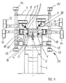
- the frame 31 is essentially one Portal-like configuration made up of individual drives for moving the pressure rollers 5 and the guide rollers 4, which are used to coat the workpiece 3, that runs on idlers 2 through the device are needed.
- the leadership roles 4, which are arranged essentially parallel to the support roller 2 in FIG and rotate with the movement of the workpiece 3, serve primarily as a support and guidance of the workpiece 3 or the casing material 30 when the workpiece 3 passes through the device.
- Pressure rollers 5 which, in the illustration according to FIG. 1, above the workpiece 3 are arranged, for guiding and pressing the sheathing material 30, which is only indicated here above the workpiece 3 and at least over Subareas of the outer contour of the workpiece 3, covering this outer contour, to be ordered.
- the material is in a not known, known to those skilled in the art upstream point of the device, for example fed from a reel, coated with adhesive or the like, heated if necessary and then on the workpiece 3, also fed to the pressure zone, is pressed on.
- Coating material 30 roughly positioned on the workpiece 3 must now be included With the help of the pressure rollers 5, for example, around corners, radii or other sections of the workpiece 3 are bent around and also pressed there, in order to achieve good adhesion of the covering material 30 to the workpiece 3.
- a number of those shown in FIG illustrated frames 31 arranged one behind the other along the machine bed 1 and take over partial sections of the forming of the covering material 30 and pressing.
- a pressure roller 5 presses from above on the workpiece 3 near the right edge of the workpiece 3
- another Pinch roller 5 presses the wrapping material 30 near the upper left Edge on the side surface of the workpiece 3.
- the workpiece 3 shown here has a particularly simple, namely rectangular shape, typical profiles that are manufactured on devices according to the invention, sometimes complex Joining of radii, bevels, angles and other form elements on.
- the guide rollers 4 and the pressure rollers 5 is a separate drive for all three such directions of movement intended.
- a lifting drive is thus, for example, for the right pressure roller 5 14 and a horizontal drive 12 and a swivel drive 7 are provided with which the pressure roller 5 shifted horizontally and vertically and parallel about an axis can be rotated to the direction 29 of the workpiece 3.
- the structure the drives 12, 14 and the corresponding other drives 11, 13 for the others Sheathing rolls are not to be described further here, since they are here conventional, for example by means of electric motor drives and an axis controller controlled drives can act, for example, via lifting spindles or the like the movement of the motors 12, 14 onto the pressure roller 5 transfer. It is of course conceivable to do this other drives such as hydraulic or pneumatic drives or other electrical drive configurations to choose, this is the specialist with his knowledge of drive technology readily available.
- a pressure roller 5 is used, for example Pivot and preload gear 7 provided, in addition to the pivoting around an axis parallel to the direction 29 of the workpiece 3 another so-called Toe-in adjustment, which will be explained later.
- a Such toe-in adjustment serves for the local compression or expansion of the sheathing material 30, which is beneficial for certain wrapping operations is.
- a swivel gear 18 is also provided for the guide rollers 4, with which the guide rollers 4 from the position shown in Figure 1 with approximately horizontal Axis of rotation into a position shown, for example, in FIG. 2 with an approximately vertical position Axis of rotation can be brought. Due to the simultaneous height and Transverse adjustment of the guide rollers 4 can the guide rollers 4 both, as in Figure 1 shown, take over 3 support functions below the workpiece, too can, as shown for example in the left half of Figure 3, leadership functions take over in the horizontal direction for workpiece 3.
- the crossbeam 9, which is arranged above the working space of the frame 31, is connected to the lifting drives 13, 14 of the pressure rollers 5 or guide rollers 4 and stabilizes these lifting drives 13, 14 and thus the overall structure of the frame 31.
- This is a particularly rigid structure and only slight deviations Pressure rollers 5 or guide rollers 4 can be realized.
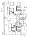
- FIG. 2 is a different position of the pressure rollers 5 and Guide rollers 4 shown on a device according to Figure 1, in which the workpiece 3 on the rotatably arranged support rollers 2, which around a shaft 16 if necessary can rotate driven, rests and conveyed through the frames 31 becomes.
- the workpiece 3 according to FIG. 2 has an approximately trapezoidal shape Cross section on, with the sheathing material 30 on the short side of the trapezoid is placed and from the pressure rollers 5 to the beveled surfaces of the Trapezes is created.
- the guide rollers 4 are not further in the configuration here needed because the pressure rollers 5 essentially the function of centered guiding take over the workpiece 3 and are therefore laterally in a rest position retracted from the workpiece 3.
- the guide rollers 4 are pivoted at least by a pivot angle of 90 ° can be moved from a position from a substantially vertical axis of rotation in a position with a substantially horizontal axis of rotation as in Figure 1 to become.
- FIG. 3 shows a section of FIG Pressure rollers 5 and the guide rollers 4 shown on a workpiece 3, wherein the right pressure roller 5 presses on the workpiece 3 from above and the left pressure roller 5 encased the workpiece 3 on a side edge.
- the guide rollers 4 lead the workpiece 3 in the vertical and horizontal directions, the right guide roller 4 forms a counter bearing for the upper right pressure roller 5, and the left guide roller 4 effects a lateral guidance of the workpiece 3.
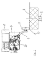
- FIG 4 is a plan view of a series arrangement of four frames 31 of a device according to the invention to recognize how the different Sheathing stations of each frame 31 are connected in series.
- the series of A total of four idlers 2 can be seen on which the workpiece 3 through the casing channel runs in the direction of the flow direction 29, the example Racks 31 on the machine bed that are combined in modules in a four-way arrangement 1 are arranged one behind the other.
- the Pressure rollers 5 are aligned essentially with a horizontal direction of rotation and the guide rollers 4 have essentially vertical directions of rotation,
- a The device according to the invention consists of a plurality of such frames 31, wherein the number of frames 31 and their sequence primarily by the Wrapping operation to be determined.
- FIGs 5 and 6 are detailed views of the swivel and Preload gear 7 is shown, with which the pressure roller 5, which on a holder 6th is rotatably supported, for example in the position shown in Figure 5 with about horizontal axis of rotation in any other position, for example with a vertical one Axis of rotation or any intermediate position can be brought.
- the Workpiece 3, which in turn rests on the support roller 2, is thus only one schematically indicated coating material 30 coated, the pressure roller 5 according to FIG. 5, the sheathing material 30 in the upper left corner of the workpiece 3 presses.
- the swivel and preload gear 7 is by two Individual drives 8 and 21, here drives with an electric motor, driven, in particular in Figures 6a and 6b, the adjustment devices inside the Pivot and preload gear 7 can be seen.
- the pure swivel movement the pressure roller 5 is realized with the help of a worm gear, which consists of a Worm wheel 25 and a worm 23 and one not shown Motor 8 is driven.
- the worm 23 pivots the flange 20, on which the holder 6 of the pressure roller 5 is fastened about an axis substantially is parallel to the direction 29 of the workpiece 3, so that the pressure roller 5 can be swiveled continuously around this axis.
- toe-in In addition to this pure swivel movement, it is due to technological properties of the sheathing material 30 important that a so-called toe-in can be set with which the sheathing material 30 is locally compressed and so that, for example, wrinkle-free can be pressed onto the workpiece 3.
- This so-called toe-in the term of toe-in known from vehicle technology is a slight, usually only a few degrees absolute inclination of the pressure roller 5 relative to the direction 29 of the Workpiece 3, so that the pressure roller 5 a force transversely to the direction 29 exerts on the sheathing material 30 and thus, for example, drapery. The like prevented.
- This toe-in setting must be in any vertical or horizontal Position and be possible in any pivot position of the pressure roller 5, for which purpose in the Execution according to FIG. 6a or 6b centrally to the hollow shaft 27 Worm wheel an adjustment also provided with a worm drive the holder 6 of the pressure roller 5 allowed.
- a drive 21, for example an electric drive, a worm 22 operated via a Central shaft 28 actuates a toothing 19 with which the holder 6 is pivoted about an axis can be the at least portions perpendicular to the direction 29 of the workpiece 3.
- the Elbow of the holder 6 and its flange can be different achieve slight toe-in settings of the pressure roller 5, which is basically are known from generic devices and set there by hand become.
- FIGS. 7a and 7b show a longitudinal and cross section through an embodiment the device according to the invention shown in Figure 1, in which the frames 31 are adjustable along the direction 29 of the workpieces 3.
- the frames 31 are adjustable along the direction 29 of the workpieces 3.
- the sled 33 run here on the rail 32 in a generally known manner linearly and are of drives, not shown, move to a position to be specified in each case, for example due to the technological boundary conditions in the casing be required.
- FIGS. 7a and 7b it can also be seen in FIGS. 7a and 7b that in an embodiment of the invention Setting up fully automated frames 31 and manually adjustable frames 35 can be combined with each other.
- manually adjustable Frames 35 are in turn guided on slides 34 and include those from the prior art Known adjustment options for the sheathing tools 4, 5.
Landscapes
- Engineering & Computer Science (AREA)
- Life Sciences & Earth Sciences (AREA)
- Manufacturing & Machinery (AREA)
- Mechanical Engineering (AREA)
- Wood Science & Technology (AREA)
- Forests & Forestry (AREA)
- Lining Or Joining Of Plastics Or The Like (AREA)
- Electrical Discharge Machining, Electrochemical Machining, And Combined Machining (AREA)
- Lead Frames For Integrated Circuits (AREA)
- Veneer Processing And Manufacture Of Plywood (AREA)
- Bending Of Plates, Rods, And Pipes (AREA)
Applications Claiming Priority (2)
| Application Number | Priority Date | Filing Date | Title |
|---|---|---|---|
| DE19849306A DE19849306C2 (de) | 1998-10-27 | 1998-10-27 | Einrichtung zur Ummantelung von Werkstücken |
| DE19849306 | 1998-10-27 |
Publications (3)
| Publication Number | Publication Date |
|---|---|
| EP0997260A2 true EP0997260A2 (fr) | 2000-05-03 |
| EP0997260A3 EP0997260A3 (fr) | 2000-09-20 |
| EP0997260B1 EP0997260B1 (fr) | 2004-08-04 |
Family
ID=7885674
Family Applications (1)
| Application Number | Title | Priority Date | Filing Date |
|---|---|---|---|
| EP99121380A Expired - Lifetime EP0997260B1 (fr) | 1998-10-27 | 1999-10-27 | Dispositif pour recouvrir des pièces |
Country Status (3)
| Country | Link |
|---|---|
| EP (1) | EP0997260B1 (fr) |
| AT (1) | ATE272490T1 (fr) |
| DE (2) | DE19849306C2 (fr) |
Cited By (13)
| Publication number | Priority date | Publication date | Assignee | Title |
|---|---|---|---|---|
| WO2002058901A3 (fr) * | 2000-12-29 | 2003-08-07 | Hollman Inc | Panneau plaque a relief et procede de production de ce panneau |
| WO2005077625A1 (fr) * | 2004-02-11 | 2005-08-25 | Delle Vedove Maschinenbau Gmbh | Dispositif pour enrober un matériau profilé |
| WO2006008578A1 (fr) * | 2004-06-22 | 2006-01-26 | Delle Vedove Levigatrici Spa | Appareil pour couvrir un objet tel qu'un element profile, un panneau ou analogue |
| US7143561B2 (en) | 2001-12-12 | 2006-12-05 | Hollman, Inc. | Veneered raised panel element and method of manufacturing thereof |
| EP1754580A3 (fr) * | 2005-08-17 | 2008-02-27 | PIRAS Metalltechnik GmbH & Co. KG | Dispositif pour recouvrir ou revêtir des profilés avec un film |
| CN102452120A (zh) * | 2010-10-20 | 2012-05-16 | 苏州红呈木业有限公司 | 木地板加工成形装置 |
| DE102011053064A1 (de) * | 2011-08-29 | 2013-02-28 | Düspohl Maschinenbau Gmbh | Vorrichtung und Verfahren zum Umrüsten von Profilummantelungsmaschinen |
| EP2572862A1 (fr) * | 2011-09-22 | 2013-03-27 | Düspohl Maschinenbau GmbH | Machine de revêtement de profilés |
| DE102017129230A1 (de) | 2017-12-08 | 2019-06-13 | Heinrich Ebbinghaus | Ummantelungsvorrichtung |
| IT202200002024A1 (it) * | 2022-02-04 | 2023-08-04 | Ecosys S R L | Apparato per lavorazione e/o trattamento di una regione di bordo di un pezzo da lavorare |
| CN118181623A (zh) * | 2024-04-09 | 2024-06-14 | 桂林橡胶设计院有限公司 | 换辊装置及自动换辊系统 |
| CN119058078A (zh) * | 2024-11-01 | 2024-12-03 | 上海凯锐恩半导体科技有限公司 | 一种平行度可调的双层真空热压成型设备 |
| EP4023404B1 (fr) * | 2020-11-20 | 2025-12-31 | IMA Schelling Deutschland GmbH | Procédé de fonctionnement d'une machine à bois |
Families Citing this family (5)
| Publication number | Priority date | Publication date | Assignee | Title |
|---|---|---|---|---|
| DE10140673B4 (de) * | 2001-08-24 | 2005-09-01 | SCHÜCO International KG | Verfahren und Vorrichtung zum Foliieren von Profilen |
| DE102005003212B4 (de) * | 2005-01-24 | 2008-08-14 | Lisa Dräxlmaier GmbH | Vorrichtung und Verfahren zum Kaschieren von Dekorträgern |
| EP2345518B1 (fr) * | 2010-01-18 | 2014-04-23 | Homag Holzbearbeitungssysteme AG | Dispositif et procédé destinés au revêtement de pièces à usiner |
| CN113352595B (zh) * | 2021-06-02 | 2022-12-06 | 广东拓斯达科技股份有限公司 | 光驰镀膜机 |
| CN114193566B (zh) * | 2021-12-08 | 2022-10-28 | 柳州市悟新木工机械有限公司 | 多手自动小拼机 |
Family Cites Families (6)
| Publication number | Priority date | Publication date | Assignee | Title |
|---|---|---|---|---|
| DE8806277U1 (de) * | 1988-05-11 | 1988-09-08 | Friz Maschinenbau GmbH, 7102 Weinsberg | Maschine zum Ummanteln von Werkstücken |
| DE4232697A1 (de) * | 1992-09-30 | 1994-03-31 | Schmidt Josef | Maschine zum Beschichten von Profilen mit Folie |
| GB2309413B (en) * | 1993-08-02 | 1997-12-10 | Honda Motor Co Ltd | Sheet sticking apparatus and sheet sticking method |
| FR2721549B1 (fr) * | 1994-06-24 | 1996-08-14 | Prometub Ind | Procédé et appareil de fixation par formage à chaud d'une feuille de stratifié sur un élément-support. |
| DE19508864C1 (de) * | 1995-03-11 | 1996-01-18 | Wessel Karl Heinz | Maschine zum Ummanteln von länglichen Werkstücken |
| DE19708850C2 (de) * | 1997-03-05 | 1999-01-07 | Wessel Karl Heinz | Ummantelungsmaschine für längliche Werkstücke |
-
1998
- 1998-10-27 DE DE19849306A patent/DE19849306C2/de not_active Expired - Fee Related
-
1999
- 1999-10-27 DE DE59910119T patent/DE59910119D1/de not_active Expired - Lifetime
- 1999-10-27 AT AT99121380T patent/ATE272490T1/de active
- 1999-10-27 EP EP99121380A patent/EP0997260B1/fr not_active Expired - Lifetime
Cited By (20)
| Publication number | Priority date | Publication date | Assignee | Title |
|---|---|---|---|---|
| WO2002058901A3 (fr) * | 2000-12-29 | 2003-08-07 | Hollman Inc | Panneau plaque a relief et procede de production de ce panneau |
| CN100420554C (zh) * | 2000-12-29 | 2008-09-24 | 霍尔曼公司 | 镶面凸板元件其制造方法 |
| US7143561B2 (en) | 2001-12-12 | 2006-12-05 | Hollman, Inc. | Veneered raised panel element and method of manufacturing thereof |
| WO2005077625A1 (fr) * | 2004-02-11 | 2005-08-25 | Delle Vedove Maschinenbau Gmbh | Dispositif pour enrober un matériau profilé |
| DE102004006569A1 (de) * | 2004-02-11 | 2005-09-15 | Delle Vedove Maschinenbau Gmbh | Vorrichtung zum Ummanteln von Profilmaterial |
| DE102004006569B4 (de) * | 2004-02-11 | 2006-01-19 | Delle Vedove Maschinenbau Gmbh | Vorrichtung zum Ummanteln von Profilmaterial |
| WO2006008578A1 (fr) * | 2004-06-22 | 2006-01-26 | Delle Vedove Levigatrici Spa | Appareil pour couvrir un objet tel qu'un element profile, un panneau ou analogue |
| EP1754580A3 (fr) * | 2005-08-17 | 2008-02-27 | PIRAS Metalltechnik GmbH & Co. KG | Dispositif pour recouvrir ou revêtir des profilés avec un film |
| CN102452120A (zh) * | 2010-10-20 | 2012-05-16 | 苏州红呈木业有限公司 | 木地板加工成形装置 |
| EP2565015A1 (fr) * | 2011-08-29 | 2013-03-06 | Düspohl Maschinenbau GmbH | Dispositif et procédé destinés au rééquipement de machines d'enrobage de profilés |
| DE102011053064A1 (de) * | 2011-08-29 | 2013-02-28 | Düspohl Maschinenbau Gmbh | Vorrichtung und Verfahren zum Umrüsten von Profilummantelungsmaschinen |
| DE102011053064B4 (de) * | 2011-08-29 | 2014-02-27 | Düspohl Maschinenbau Gmbh | Vorrichtung und Verfahren zum Umrüsten von Profilummantelungsmaschinen |
| EP2572862A1 (fr) * | 2011-09-22 | 2013-03-27 | Düspohl Maschinenbau GmbH | Machine de revêtement de profilés |
| DE102017129230A1 (de) | 2017-12-08 | 2019-06-13 | Heinrich Ebbinghaus | Ummantelungsvorrichtung |
| EP4023404B1 (fr) * | 2020-11-20 | 2025-12-31 | IMA Schelling Deutschland GmbH | Procédé de fonctionnement d'une machine à bois |
| IT202200002024A1 (it) * | 2022-02-04 | 2023-08-04 | Ecosys S R L | Apparato per lavorazione e/o trattamento di una regione di bordo di un pezzo da lavorare |
| EP4223469A1 (fr) * | 2022-02-04 | 2023-08-09 | ECOSYS S.r.l. | Appareil pour travailler et/ou traiter une zone de bord d'une pièce à usiner |
| CN118181623A (zh) * | 2024-04-09 | 2024-06-14 | 桂林橡胶设计院有限公司 | 换辊装置及自动换辊系统 |
| CN118181623B (zh) * | 2024-04-09 | 2025-10-03 | 桂林橡胶设计院有限公司 | 换辊装置及自动换辊系统 |
| CN119058078A (zh) * | 2024-11-01 | 2024-12-03 | 上海凯锐恩半导体科技有限公司 | 一种平行度可调的双层真空热压成型设备 |
Also Published As
| Publication number | Publication date |
|---|---|
| ATE272490T1 (de) | 2004-08-15 |
| DE59910119D1 (de) | 2004-09-09 |
| EP0997260B1 (fr) | 2004-08-04 |
| EP0997260A3 (fr) | 2000-09-20 |
| DE19849306A1 (de) | 2000-05-11 |
| DE19849306C2 (de) | 2002-12-05 |
Similar Documents
| Publication | Publication Date | Title |
|---|---|---|
| EP0997260B1 (fr) | Dispositif pour recouvrir des pièces | |
| DE3534428C2 (fr) | ||
| EP0672480B1 (fr) | Système de transport | |
| DE69309312T2 (de) | Verfahren und vorrichtung zum wechseln von formen in warmformpressen | |
| DE112011102029B4 (de) | Herstellungsvorrichtung für eine kantig gewickelte Spule | |
| EP2152446B1 (fr) | Dispositif de centrage pour des pièces à usiner planes dans une presse | |
| DE3424802C2 (de) | Verfahren und Vorrichtung zum Pressen einer gekrümmten Verbundglasscheibe durch ein Preßwalzenpaar | |
| EP1784291A1 (fr) | Bearbeitungseinrichtung, insbesondere plattenaufteilsägeeinrichtung | |
| DE102010004781B4 (de) | Trenn- und Abisoliereinrichtung für eine Kabelverarbeitungsmaschine | |
| AT405145B (de) | Anordnung und verfahren zur spanlosen bearbeitung von material oder werkstücken | |
| DE10058367B4 (de) | Walzvorrichtung mit Einspannmitteln zum Greifen eines Stahlstreifens | |
| DE102012009108A1 (de) | Transfervorrichtung für Werkstücke | |
| DE69000888T2 (de) | Verfahren und vorrichtung zum abschraegen von einspringenden ecken bei tafeln aus farbigem oder nicht farbigem flachglas. | |
| EP1782896B1 (fr) | Procédé pour le formage d' une pièce et machine de laminage | |
| EP2289643A2 (fr) | Dispositif pour le pliage de longues pièces usinées | |
| DE9414501U1 (de) | Bearbeitungsmaschine mit relativverschiebbaren Drehvorrichtungen | |
| EP3016760B1 (fr) | Dispositif et procédé pour transférer un élément et système d'outil | |
| EP3515626B1 (fr) | Machine-outil et procédé d'usinage de pièces en forme de plaque | |
| DE212022000352U1 (de) | Produktionslinie zum hydraulischen Stanzen von Profilen mit mehreren Stationen | |
| EP2380674A2 (fr) | Tête de pliage extensible | |
| DE102019006264B4 (de) | Förderanlage zum Transportieren von Gegenständen im Karosseriebau der Kfz-Industrie, Verfahren zum Transportieren von mehrachsigen Robotern und Bauteilen sowie Verwendung eines Drehtisches und eines Magazins oder Haltebahnhofs für Roboter im Zusammenhang mit derartigen Fördervorrichtungen und Steuerung zum Durchführen eines derartigen Verfahrens | |
| EP0210572A1 (fr) | Appareil de montage automatique de pièces d'oeuvre ou de parties de pièces d'oeuvre ainsi que méthode de réglage d'un tel appareil | |
| EP1387743B1 (fr) | Unite de detourage pour une machine continue commandee par programme | |
| EP1985387A1 (fr) | Machine à profiler avec plusieurs postes de formage successive et bâti pour une telle machine à profiler | |
| EP2565015A1 (fr) | Dispositif et procédé destinés au rééquipement de machines d'enrobage de profilés |
Legal Events
| Date | Code | Title | Description |
|---|---|---|---|
| PUAI | Public reference made under article 153(3) epc to a published international application that has entered the european phase |
Free format text: ORIGINAL CODE: 0009012 |
|
| AK | Designated contracting states |
Kind code of ref document: A2 Designated state(s): AT BE CH CY DE DK ES FI FR GB GR IE IT LI LU MC NL PT SE |
|
| AX | Request for extension of the european patent |
Free format text: AL;LT;LV;MK;RO;SI |
|
| PUAL | Search report despatched |
Free format text: ORIGINAL CODE: 0009013 |
|
| AK | Designated contracting states |
Kind code of ref document: A3 Designated state(s): AT BE CH CY DE DK ES FI FR GB GR IE IT LI LU MC NL PT SE |
|
| AX | Request for extension of the european patent |
Free format text: AL;LT;LV;MK;RO;SI |
|
| RIC1 | Information provided on ipc code assigned before grant |
Free format text: 7B 29C 63/04 A, 7F 16C 13/00 B |
|
| 17P | Request for examination filed |
Effective date: 20010315 |
|
| AKX | Designation fees paid |
Free format text: AT BE CH CY DE DK ES FI FR GB GR IE IT LI LU MC NL PT SE |
|
| AXX | Extension fees paid |
Free format text: AL PAYMENT 20010315;LT PAYMENT 20010315;LV PAYMENT 20010315;MK PAYMENT 20010315;RO PAYMENT 20010315;SI PAYMENT 20010315 |
|
| 17Q | First examination report despatched |
Effective date: 20010918 |
|
| GRAP | Despatch of communication of intention to grant a patent |
Free format text: ORIGINAL CODE: EPIDOSNIGR1 |
|
| GRAS | Grant fee paid |
Free format text: ORIGINAL CODE: EPIDOSNIGR3 |
|
| GRAA | (expected) grant |
Free format text: ORIGINAL CODE: 0009210 |
|
| AK | Designated contracting states |
Kind code of ref document: B1 Designated state(s): AT BE CH CY DE DK ES FI FR GB GR IE IT LI LU MC NL PT SE |
|
| AX | Request for extension of the european patent |
Extension state: AL LT LV MK RO SI |
|
| PG25 | Lapsed in a contracting state [announced via postgrant information from national office to epo] |
Ref country code: NL Free format text: LAPSE BECAUSE OF FAILURE TO SUBMIT A TRANSLATION OF THE DESCRIPTION OR TO PAY THE FEE WITHIN THE PRESCRIBED TIME-LIMIT Effective date: 20040804 Ref country code: IE Free format text: LAPSE BECAUSE OF FAILURE TO SUBMIT A TRANSLATION OF THE DESCRIPTION OR TO PAY THE FEE WITHIN THE PRESCRIBED TIME-LIMIT Effective date: 20040804 Ref country code: GB Free format text: LAPSE BECAUSE OF FAILURE TO SUBMIT A TRANSLATION OF THE DESCRIPTION OR TO PAY THE FEE WITHIN THE PRESCRIBED TIME-LIMIT Effective date: 20040804 Ref country code: FR Free format text: LAPSE BECAUSE OF FAILURE TO SUBMIT A TRANSLATION OF THE DESCRIPTION OR TO PAY THE FEE WITHIN THE PRESCRIBED TIME-LIMIT Effective date: 20040804 Ref country code: FI Free format text: LAPSE BECAUSE OF FAILURE TO SUBMIT A TRANSLATION OF THE DESCRIPTION OR TO PAY THE FEE WITHIN THE PRESCRIBED TIME-LIMIT Effective date: 20040804 Ref country code: CY Free format text: LAPSE BECAUSE OF FAILURE TO SUBMIT A TRANSLATION OF THE DESCRIPTION OR TO PAY THE FEE WITHIN THE PRESCRIBED TIME-LIMIT Effective date: 20040804 |
|
| REG | Reference to a national code |
Ref country code: GB Ref legal event code: FG4D Free format text: NOT ENGLISH |
|
| REG | Reference to a national code |
Ref country code: CH Ref legal event code: EP |
|
| REG | Reference to a national code |
Ref country code: IE Ref legal event code: FG4D Free format text: GERMAN |
|
| REF | Corresponds to: |
Ref document number: 59910119 Country of ref document: DE Date of ref document: 20040909 Kind code of ref document: P |
|
| PG25 | Lapsed in a contracting state [announced via postgrant information from national office to epo] |
Ref country code: LU Free format text: LAPSE BECAUSE OF NON-PAYMENT OF DUE FEES Effective date: 20041027 |
|
| PG25 | Lapsed in a contracting state [announced via postgrant information from national office to epo] |
Ref country code: MC Free format text: LAPSE BECAUSE OF NON-PAYMENT OF DUE FEES Effective date: 20041031 Ref country code: LI Free format text: LAPSE BECAUSE OF NON-PAYMENT OF DUE FEES Effective date: 20041031 Ref country code: CH Free format text: LAPSE BECAUSE OF NON-PAYMENT OF DUE FEES Effective date: 20041031 Ref country code: BE Free format text: LAPSE BECAUSE OF NON-PAYMENT OF DUE FEES Effective date: 20041031 |
|
| PG25 | Lapsed in a contracting state [announced via postgrant information from national office to epo] |
Ref country code: SE Free format text: LAPSE BECAUSE OF FAILURE TO SUBMIT A TRANSLATION OF THE DESCRIPTION OR TO PAY THE FEE WITHIN THE PRESCRIBED TIME-LIMIT Effective date: 20041104 Ref country code: GR Free format text: LAPSE BECAUSE OF FAILURE TO SUBMIT A TRANSLATION OF THE DESCRIPTION OR TO PAY THE FEE WITHIN THE PRESCRIBED TIME-LIMIT Effective date: 20041104 Ref country code: DK Free format text: LAPSE BECAUSE OF FAILURE TO SUBMIT A TRANSLATION OF THE DESCRIPTION OR TO PAY THE FEE WITHIN THE PRESCRIBED TIME-LIMIT Effective date: 20041104 |
|
| PG25 | Lapsed in a contracting state [announced via postgrant information from national office to epo] |
Ref country code: ES Free format text: LAPSE BECAUSE OF FAILURE TO SUBMIT A TRANSLATION OF THE DESCRIPTION OR TO PAY THE FEE WITHIN THE PRESCRIBED TIME-LIMIT Effective date: 20041115 |
|
| NLV1 | Nl: lapsed or annulled due to failure to fulfill the requirements of art. 29p and 29m of the patents act | ||
| LTIE | Lt: invalidation of european patent or patent extension |
Effective date: 20040804 |
|
| GBV | Gb: ep patent (uk) treated as always having been void in accordance with gb section 77(7)/1977 [no translation filed] |
Effective date: 20040804 |
|
| REG | Reference to a national code |
Ref country code: IE Ref legal event code: FD4D |
|
| BERE | Be: lapsed |
Owner name: FRITZ ROBERING G.M.B.H. & CO. KG Effective date: 20041031 |
|
| PLBE | No opposition filed within time limit |
Free format text: ORIGINAL CODE: 0009261 |
|
| STAA | Information on the status of an ep patent application or granted ep patent |
Free format text: STATUS: NO OPPOSITION FILED WITHIN TIME LIMIT |
|
| REG | Reference to a national code |
Ref country code: CH Ref legal event code: PL |
|
| 26N | No opposition filed |
Effective date: 20050506 |
|
| EN | Fr: translation not filed | ||
| PG25 | Lapsed in a contracting state [announced via postgrant information from national office to epo] |
Ref country code: IT Free format text: LAPSE BECAUSE OF NON-PAYMENT OF DUE FEES Effective date: 20051027 |
|
| BERE | Be: lapsed |
Owner name: FRITZ *ROBERING G.M.B.H. & CO. K.G. Effective date: 20041031 |
|
| PG25 | Lapsed in a contracting state [announced via postgrant information from national office to epo] |
Ref country code: PT Free format text: LAPSE BECAUSE OF NON-PAYMENT OF DUE FEES Effective date: 20050104 |
|
| PGRI | Patent reinstated in contracting state [announced from national office to epo] |
Ref country code: IT Effective date: 20091201 |
|
| PGFP | Annual fee paid to national office [announced via postgrant information from national office to epo] |
Ref country code: IT Payment date: 20130917 Year of fee payment: 15 |
|
| PGFP | Annual fee paid to national office [announced via postgrant information from national office to epo] |
Ref country code: AT Payment date: 20130918 Year of fee payment: 15 Ref country code: DE Payment date: 20131010 Year of fee payment: 15 |
|
| REG | Reference to a national code |
Ref country code: DE Ref legal event code: R119 Ref document number: 59910119 Country of ref document: DE |
|
| REG | Reference to a national code |
Ref country code: AT Ref legal event code: MM01 Ref document number: 272490 Country of ref document: AT Kind code of ref document: T Effective date: 20141027 |
|
| PG25 | Lapsed in a contracting state [announced via postgrant information from national office to epo] |
Ref country code: DE Free format text: LAPSE BECAUSE OF NON-PAYMENT OF DUE FEES Effective date: 20150501 |
|
| PG25 | Lapsed in a contracting state [announced via postgrant information from national office to epo] |
Ref country code: IT Free format text: LAPSE BECAUSE OF NON-PAYMENT OF DUE FEES Effective date: 20141027 Ref country code: AT Free format text: LAPSE BECAUSE OF NON-PAYMENT OF DUE FEES Effective date: 20141027 |