EP0997273B1 - Groupe imprimant d'une presse à bobines - Google Patents
Groupe imprimant d'une presse à bobines Download PDFInfo
- Publication number
- EP0997273B1 EP0997273B1 EP99116770A EP99116770A EP0997273B1 EP 0997273 B1 EP0997273 B1 EP 0997273B1 EP 99116770 A EP99116770 A EP 99116770A EP 99116770 A EP99116770 A EP 99116770A EP 0997273 B1 EP0997273 B1 EP 0997273B1
- Authority
- EP
- European Patent Office
- Prior art keywords
- plate cylinder
- gear wheel
- drive
- drive motor
- cylinder
- Prior art date
- Legal status (The legal status is an assumption and is not a legal conclusion. Google has not performed a legal analysis and makes no representation as to the accuracy of the status listed.)
- Expired - Lifetime
Links
- 238000007639 printing Methods 0.000 title claims abstract description 94
- 230000008859 change Effects 0.000 description 14
- 230000005540 biological transmission Effects 0.000 description 10
- 230000008878 coupling Effects 0.000 description 3
- 238000010168 coupling process Methods 0.000 description 3
- 238000005859 coupling reaction Methods 0.000 description 3
- 238000004519 manufacturing process Methods 0.000 description 3
- 238000007645 offset printing Methods 0.000 description 3
- 230000008901 benefit Effects 0.000 description 2
- 230000007246 mechanism Effects 0.000 description 2
- 239000000463 material Substances 0.000 description 1
- 238000000034 method Methods 0.000 description 1
- 230000008569 process Effects 0.000 description 1
- 230000009467 reduction Effects 0.000 description 1
- 238000005096 rolling process Methods 0.000 description 1
Images



Classifications
-
- B—PERFORMING OPERATIONS; TRANSPORTING
- B41—PRINTING; LINING MACHINES; TYPEWRITERS; STAMPS
- B41F—PRINTING MACHINES OR PRESSES
- B41F13/00—Common details of rotary presses or machines
- B41F13/004—Electric or hydraulic features of drives
- B41F13/0045—Electric driving devices
-
- B—PERFORMING OPERATIONS; TRANSPORTING
- B41—PRINTING; LINING MACHINES; TYPEWRITERS; STAMPS
- B41P—INDEXING SCHEME RELATING TO PRINTING, LINING MACHINES, TYPEWRITERS, AND TO STAMPS
- B41P2213/00—Arrangements for actuating or driving printing presses; Auxiliary devices or processes
- B41P2213/70—Driving devices associated with particular installations or situations
- B41P2213/73—Driving devices for multicolour presses
- B41P2213/734—Driving devices for multicolour presses each printing unit being driven by its own electric motor, i.e. electric shaft
Definitions
- the present invention relates to an impression unit for a web-fed rotary printing press.
- the invention relates to a motor and transmission arrangement for driving the Cylinder of an impression unit in different operating modes.
- a paper web is usually replaced by one Variety of rubber-rubber printing units, in which both sides of the web with be printed on a multicolored image.
- EP-A-0 820 861 describes a printing unit of an offset rotary printing press two pairs of plate and blanket cylinders, of which the first plate cylinder and the two blanket cylinders mechanically coupled via sliding gears and are driven by a common drive.
- the second plate cylinder is with provided with its own drive.
- DE-C 35 10 822 describes a printing unit of a web-fed rotary printing press in which a common impression cylinder serves as a paper guide roller and from the two Blanket cylinders is separated.
- a common impression cylinder serves as a paper guide roller and from the two Blanket cylinders is separated.
- GB 2 309 668 discloses a rubber-to-rubber printing unit that has a flying one Plate change allows, with the plate cylinder in rolling contact with the moving Web remain, while the blanket cylinders of the printing unit alternately on the assigned blanket cylinder on or off this.
- the Blanket cylinders are over interlocking gears, z. B. spur gears, permanent coupled with each other and are via a longitudinal shaft of the main drive motor Printing press driven.
- the rubber blanket cylinders are however over couplings or further gears assigned to them are coupled to the gears of the blanket cylinders.
- the drive connection of the plate cylinder is interrupted by the corresponding clutch is activated, and the plate cylinder is powered by an auxiliary motor braked.
- the plate cylinder is replaced by the auxiliary motor accelerated to print speed before moving on to its assigned Blanket cylinder is started.
- the longitudinal shaft and the main drive motor are accordingly at least two for performing a flying plate change Auxiliary motors necessary.
- the printing unit is complicated and fragile for disturbances in the gear train caused by torsional vibrations the cylinders are driven.
- US 5,063,844 describes a web-fed rotary offset printing machine with a rubber-rubber printing unit, in which to perform a flying plate change two Plate cylinder alternately to a blanket cylinder during production printing can be turned on or off by this.
- Both blanket cylinders of the printing unit are driven and are located in Roll contact with the moving paper web, while that of the blanket cylinder parked plate cylinder uncoupled from the common drive motor and is stopped and accelerated again after changing the plate.
- DE 44 05 658 C2 describes a printing unit of a web-fed rotary offset printing press, at which a flying plate change is possible.
- the printing unit comprises two Blanket cylinders and plate cylinders assigned to them, which alternately an impression cylinder, over which the web is guided, started and by this can be turned off.
- Each of the blanket cylinders is powered by its own engine driven and drives the assigned plate cylinder via a gear train.
- the impression cylinder is driven by another motor. With this impression work it is not possible to alternately print on both sides of the web.
- JP 63 - 236651 a rubber-rubber printing unit for one Web-fed rotary printing press described in which an upper blanket cylinder and a this associated upper plate cylinder drive-coupled via a first gear train are and a lower blanket cylinder and a lower associated with it Plate cylinders are drive-coupled via a second gear train.
- a first engine drives the upper plate cylinder and a second motor drives the lower one Plate cylinder. Due to the permanent coupling of the drive gear Plate cylinder and the blanket cylinder assigned to them can do the described Printing unit can not be operated as an impression unit.
- an impression work to create for a web-fed rotary printing press that has a compact design with a reduced number of drive motors and a flying pressure plate change allowed on both sides of the track, while on the other side of the track the Printing continues.
- Another object of the present invention is to provide an impression mechanism create in which the disturbances caused by torsional vibrations are minimized become.
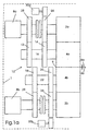
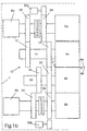
- a first embodiment comprises an impression unit 1 a web-fed rotary printing press, a first plate cylinder 2a and a first Blanket cylinder 4a, which is a first pair of cylinders for printing on a first side 6a form a moving path 6.
- the printing unit 1 further comprises a second one Plate cylinder 2b and a second blanket cylinder 4b associated therewith, the one form a second pair of cylinders for printing on the second side 6b of the web 6, which are by the one formed between the first and second blanket cylinders 4a and 4b Printing gap moved.
- the printing unit 1 further comprises a first and a second drive motor 8a, 8b, which the cylinders 2a, 2b and 4a, 4b of the printing unit 1 in different operating modes drive, which are referred to below as the first, second and third operating mode.
- the first mode of operation the moving paper web 6 is simultaneously on its first Page 6a and printed on its second side 6b, as indicated by wedges in Fig. 1a is.
- the web 6 is only from the second Cylinder pair printed on the second side 6b, while the first plate cylinder 2a des first pair of cylinders z. B. to change the (not shown) printing plates on the first Plate cylinder 2a during the printing process from the first assigned to it Blanket cylinder 4a is turned off.
- the first and the remain second blanket cylinders 4a and 4b put together so that the first Blanket cylinder 4a as. Impression cylinder is used without taking pictures at first Page 6a of the web 6 to be transferred.
- the web 6 is only from the first pair of cylinders to the first Page 6a printed, while the second plate cylinder 2b for changing the printing plates on the second plate cylinder 2b for the next print job from him assigned second blanket cylinder 4b is turned off, as shown in Fig. 1c.
- the first and second blanket cylinders 4a and 4b remain adjusted to each other, so that the second blanket cylinder 4b as an impression cylinder serves without transferring images to the second side 6b of the web 6.
- the transmission assembly 10 includes first and second movable gear 12, 14 which on the drive shaft 16 of the first Blanket cylinders 4a are arranged.
- the two movable gear wheels 12, 14 are firmly connected in the circumferential direction to the drive shaft 16 in order to Drive shaft to transmit 16 torques, but are in the axial direction on the Drive shaft 16 movable.
- the transmission assembly 10 further includes a third and a fourth movable gear 18, 20 which is axially movable on the drive shaft 22 of the second blanket cylinder 4b are arranged and fixed in the circumferential direction with the Drive shaft 22 are connected to transmit torque to the drive shaft 22.
- the gear arrangement 10 further comprises a first plate cylinder drive gear 24, which is coupled to the first plate cylinder 2a, and a second plate cylinder drive gear 26, which is coupled to the second plate cylinder 2b.
- the first drive motor 8a preferably drives via first spur gear 28 on the first movable gear 12, which with the drive shaft of first motor 8a is connected.
- the second movable gear 14 is in a axial position on the shaft 16, in which it is, as shown in Fig. 2a, in the plate cylinder drive gear 24 engages and thus drives the plate cylinder 2a.
- the second drive motor 8b preferably drives the third movable via a spur gear 29 Gear 18 on, and the fourth movable gear 20 is in an axial position on the shaft 22, in which it engages in the second plate cylinder drive gear 26 and so drives the second plate cylinder 2b.
- the first drive motor 8a drives the first movable one Gear 12 on, and the second movable gear 14 is in an axial position on the shaft 16, in which it meshes with the fourth movable gear 20, at the same time the fourth movable gear 20 meshes with the second plate cylinder drive gear 26 and so drives the second plate cylinder 2b.
- Switching the transmission arrangement 10 from the first operating mode to the second operating mode, e.g. B. by moving the second and third movable gear 14, 18 toward each of them assigned blanket cylinders 4a and 4b to be reached.
- the second drive motor 8b drives the third movable gear 18, and the fourth movable gear 20 is in one axial position in which it engages the second movable gear 14.
- the second Movable gear 14 is in an axial position on the shaft 22 in the it engages the first plate cylinder drive gear 24 as shown in Fig. 1c.
- On Switching from the first operating mode to the third operating mode can e.g. B. by moving the first movable gear 12 and the fourth movable gear 20 away from their associated blanket cylinder 4a or 4b can be achieved.
- first and a second auxiliary motor 30a, 30b can be rotated become.
- the first and second auxiliary motors 30a, 30b can be in addition to the first and the second plate cylinder drive gear 24, 26 may be arranged and the Drive gears 24, 26 z. B., as shown in the drawings, via spur gears drive or via a drive belt and associated drive pulleys.
- the second can alternatively also be used Drive motor 8b are used to turn off the plate cylinder 2a in the second Operating mode, for example, to drive a drive belt, while in the third
- the first drive motor 8a can be used to operate the second, parked plate cylinder 2b in the same way via another drive belt drive.
- the first and the third movable gear 12, 18 and / or the second and fourth movable Gear 14, 20 can be arranged on their respective shafts 16 and 22 in such a way that they are movable at the same time, e.g. B. by using a shift fork as z. B. in Manual transmissions according to the prior art is used.
- the inking units, the first and second plate cylinders 2a, 2b color feed, also via the first and second plate cylinder drive gear 24, 26th are driven.
- the inking units act as an additional load, which is added contributes to the remaining, through the elasticity of the gears and shafts of the Gear assembly 10 resulting torsional vibrations and the resulting To minimize interference.
- couplings can also be used. which an additional drive connection between the first and second Drive motor 8a, 8b and the drive shafts of the associated plate cylinders 2a, 2b create, as indicated by the dashed lines in Fig. 1a to 1c, whereby the Torsional vibrations and the associated disturbances can be further minimized can.
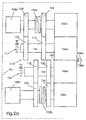
- FIGS. 2a to 2c in which comparable components with similar ones by 100 raised reference numerals includes a second embodiment of a Impression unit 101 according to the invention for a web-fed rotary printing press first plate cylinder 102a and a first blanket cylinder 104a, which together first pair of cylinders for printing a first side 106a of a moving one Form paper web 106.
- the printing unit 101 further comprises a second one Plate cylinder 102b and a second blanket cylinder 104b assigned to it, which together form a second pair of cylinders for printing on the second side 106b of FIG Form paper web 106.
- the printing unit 101 further comprises a first and a second Drive motor 108a, 108b, which the cylinders 102a, 102b and 104a, 104b of the Printing unit 101 in different operating modes, the first, second and third operating mode.
- the first operating mode the moving paper web 106 simultaneously on the first side 106a and on the second Printed page 106b, as indicated by wedges in Fig. 2a.
- the web 106 is replaced only by the second Cylinder pair printed on the second side 106b, while the first plate cylinder 102a the first pair of cylinders z. B. to change the on the first plate cylinder 102a arranged printing plates during the printing operation of the assigned to him first blanket cylinder 104a is turned off.
- the first one remains in this second mode and the second blanket cylinder 104a and 104b lined up so that the first Blanket cylinder 104a serves as an impression cylinder without taking pictures at first Page 106a to transmit the web 106.
- the transmission assembly 110 includes first and one second movable gear 112, 114 which on the drive shaft 116 of the first Blanket cylinders 104a are arranged.
- the two movable gears 112, 114 are fixedly connected to the drive shaft 116 in the circumferential direction in order to to transmit the drive shaft 116 torques, but in the axial direction on the Drive shaft 116 slidably arranged.
- the transmission assembly 110 further includes a third and fourth movable gears 118 and 120 which are axially movable on the Drive shaft 122 of the second blanket cylinder 104b are arranged, in Circumferential direction are fixedly connected to the shaft 122 to this torque transfer.
- the gear arrangement 110 further comprises one at the first Plate cylinder 102a coupled first plate cylinder drive gear 124 and one to the second plate cylinder 102b coupled second plate cylinder drive gear 126.
- the first drive motor 108a preferably exaggerates a first spur gear 128 connected to the drive shaft of the first motor 108a the first movable gear 112.
- the second movable gear 114 is in an axial position arranged on the shaft 116, in which it is in the first plate cylinder drive gear 124 engages and thus drives the first plate cylinder 102a.
- the second drive motor 108b drives the third movable gear 118 and the fourth movable gear 120 is on the Shaft 122 in an axial position in which it is simultaneously movable in the second Gear 114 and engages in the second plate cylinder drive gear 126, as shown in Fig. 2b is shown.
- Switching the transmission arrangement 110 from the first operating mode to the second operating mode can e.g. B. by simultaneously moving the first movable Gear 112 and the second movable gear 114 toward them assigned blanket cylinder 104a to be reached.
- the first drive motor 108a drives the first movable one Gear 112 on, and the second movable gear 114 is in an axial Position on the shaft 116, in which it is simultaneously in the fourth movable gear 120 and engages the first plate cylinder drive gear 124 so as to engage the first To drive plate cylinder 102a.
- Switching the gear arrangement 110 from the first mode in the third mode can, for. B. by moving the third and fourth movable gear 118, 120 away from the blanket cylinder 104b assigned to them can be achieved.
- the first drive motor 108a is in the second operating mode only coupled to the first plate cylinder 102a to the parked first Plate cylinder 102a for the flying change of the printing plates arranged thereon to drive individually.
- the second drive motor 108b is only on the second plate cylinder 102b coupled to the parked second one Plate cylinder 102b for the flying change of the printing plates arranged thereon to drive individually.
- the first and second drive motor 108a, 108b via a first and second clutch 132a and 132b the plate cylinders 102a and 102b assigned to them, as shown in FIG. 2a to 2c is shown.
- the first clutch 132a is only in FIG second operating mode closed and opened in the first and third operating modes, while the second clutch 132b is closed only in the third mode and in the first and second operating mode is open.
- the advantage of the above Use of clutches 132a and 132b is that when the printing unit 101st is operated as an impression mechanism, none during a flying plate change additional auxiliary motors for rotating the first and second plate cylinders 102a, 102b are needed.
- first and second Plate cylinders 102a, 102b of the second embodiment of the present invention by means of additional auxiliary motors or friction rollers or a drive belt and associated drive pulleys to rotate as previously related with the first embodiment of the present invention.
- the inking units, the first and second Feed plate cylinders 102a, 102b via the first and second plate cylinder drive gears 124, 126 are driven, the inking units an additional form pushed load, through which the torsional vibrations and thus connected disturbances in the printing unit 101 can be further minimized.
- a further reduction in torsional vibrations and avoidance of through Play between the second and fourth movable gears 114 and 120 Duplication, especially in the first operating mode, can be caused by attachment a brake 117, 123 on the drive shafts 116 and / or 122 are effected.
Landscapes
- Engineering & Computer Science (AREA)
- Mechanical Engineering (AREA)
- Inking, Control Or Cleaning Of Printing Machines (AREA)
- Rotary Presses (AREA)
Claims (20)
- Groupe unitaire d'impression pour une rotative d'impression à bobines ou continue, comportant une première paire de cylindres englobant un premier cylindre porte-plaque (2a) et un premier cylindre de blanchet (4a) qui lui est associé,
une seconde paire de cylindres englobant un second cylindre porte-plaque (2b) et un second cylindre de blanchet (4b) qui lui est associé,
un premier moteur d'entraínement (8a), et
un second moteur d'entraínement (8b),
le premier moteur d'entraínement (8a) entraínant, dans un premier mode de fonctionnement, la première paire de cylindres et, indépendamment de cela, le second moteur d'entraínement (8b) la seconde paire de cylindres,
caractérisé en ce que l'entraínement des cylindres (2a, 2b, 4a, 4b) est effectué par l'intermédiaire d'un agencement de transmission (10), qui comprend une première et une seconde roue dentée (12, 14) disposée de manière axialement mobile sur un arbre d'entraínement (16) associé au premier cylindre de blanchet (4a), une troisième et une quatrième roue dentée (18, 20) disposée de manière axialement mobile sur un arbre d'entraínement (22) associé au second cylindre de blanchet (4b), une première roue dentée d'entraínement de cylindre porte-plaque (24) couplée au premier cylindre porte-plaque (2a) et une seconde roue dentée d'entraínement de cylindre porte-plaque (26) couplée au second cylindre porte-plaque (2b) de façon telle, que dans un second mode de fonctionnement, le premier moteur d'entraínement (8a) entraíne le premier cylindre de blanchet (4a) et la seconde paire de cylindres, et dans un troisième mode de fonctionnement, le second moteur d'entraínement (8b) entraíne le second cylindre de blanchet (4b) et la première paire de cylindres. - Groupe unitaire d'impression selon la revendication 1, caractérisé en ce que dans le second mode de fonctionnement, le premier cylindre porte-plaque (2a) est entraíné individuellement par un premier moteur auxiliaire (30a).
- Groupe unitaire d'impression selon la revendication 1, caractérisé en ce que dans le troisième mode de fonctionnement, le second cylindre porte-plaque (2b) est entraíné individuellement par un second moteur auxiliaire (30b).
- Groupe unitaire d'impression selon l'une des revendications précédentes, caractérisé en ce que dans le premier mode de fonctionnement, le premier moteur d'entraínement (8a), pour l'entraínement du premier cylindre porte-plaque (2a), entraíne la première roue dentée mobile (12), et la seconde roue dentée mobile (14) est en prise avec la première roue dentée d'entraínement de cylindre porte-plaque (24), et le second moteur d'entraínement (8b), pour l'entraínement du second cylindre porte-plaque (2b), entraíne la troisième roue dentée mobile (18), et la quatrième roue dentée mobile (20) est en prise avec la seconde roue dentée d'entraínement de cylindre porte-plaque (26).
- Groupe unitaire d'impression selon l'une des revendications précédentes, caractérisé en ce que dans le second mode de fonctionnement, le premier moteur d'entraínement (8a) entraíne la première roue dentée mobile (12), et la seconde roue dentée mobile (14) est en prise avec la quatrième roue dentée mobile (20), et la quatrième roue dentée mobile (20) est en prise avec la seconde roue dentée d'entraínement de cylindre porte-plaque (26).
- Groupe unitaire d'impression selon l'une des revendications précédentes, caractérisé en ce que dans le troisième mode de fonctionnement, le second moteur d'entraínement (8b) entraíne la troisième roue dentée mobile (18), et la quatrième roue dentée mobile (20) est en prise avec la seconde roue dentée mobile (14), et la seconde roue dentée mobile (14) est en prise avec la première roue dentée d'entraínement de cylindre porte-plaque (24).
- Groupe unitaire d'impression selon l'une des revendications précédentes, caractérisé en ce que la première roue dentée mobile (12) peut être déplacée en commun avec la troisième roue dentée mobile (18).
- Groupe unitaire d'impression selon l'une des revendications précédentes, caractérisé en ce que la seconde roue dentée mobile (14) peut être déplacée en commun avec la quatrième roue dentée mobile (20).
- Groupe unitaire d'impression pour une rotative d'impression à bobines ou continue, comportant une première paire de cylindres englobant un premier cylindre porte-plaque (102a) et un premier cylindre de blanchet (104a) qui lui est associé,
une seconde paire de cylindres englobant un second cylindre porte-plaque (102b) et un second cylindre de blanchet (104b) qui lui est associé,
un premier moteur d'entraínement (108a), et
un second moteur d'entraínement (108b),
le premier moteur d'entraínement (108a) entraínant, dans un premier mode de fonctionnement, la première paire de cylindres et, indépendamment de cela, le second moteur d'entraínement (108b) la seconde paire de cylindres,
caractérisé en ce que l'entraínement des cylindres (102a, 102b, 104a, 104b) est effectué par l'intermédiaire d'un agencement de transmission (110), qui comprend une première et une seconde roue dentée (112, 114) disposée de manière axialement mobile sur un arbre d'entraínement (116) associé au premier cylindre de blanchet (104a), une troisième et une quatrième roue dentée (118, 120) disposée de manière axialement mobile sur un arbre d'entraínement (122) associé au second cylindre de blanchet (104b), une première roue dentée d'entraínement de cylindre porte-plaque (124) couplée au premier cylindre porte-plaque (102a) et une seconde roue dentée d'entraínement de cylindre porte-plaque (126) couplée au second cylindre porte-plaque (102b) de façon telle, que dans un second mode de fonctionnement, le second moteur d'entraínement (108b) entraíne la seconde paire de cylindres et le premier cylindre de blanchet (104a), et dans un troisième mode de fonctionnement, le premier moteur d'entraínement (108a) entraíne la première paire de cylindres et le second cylindre de blanchet (104b). - Groupe unitaire d'impression selon la revendication 9, caractérisé en ce que dans le second mode de fonctionnement, le premier moteur d'entraínement (108a) est couplé exclusivement au premier cylindre porte-plaque 102a) en vue de pouvoir entraíner individuellement le premier cylindre porte-plaque (102a) pour le changement des plaques d'impression qui y sont disposées, le premier cylindre porte-plaque (102a) se trouvant en position de dégagement.
- Groupe unitaire d'impression selon la revendication 10, caractérisé en ce que le premier moteur d'entraínement (108a) est couplé au premier cylindre porte-plaque (102a) par l'intermédiaire d'un accouplement ou embrayage (132a), qui est fermé dans le second mode de fonctionnement et est ouvert dans le premier et le troisième mode de fonctionnement.
- Groupe unitaire d'impression selon l'une des revendications 9 à 11, caractérisé en ce que dans le troisième mode de fonctionnement, le second moteur d'entraínement (108b) est couplé exclusivement au second cylindre porte-plaque (102b), en vue de pouvoir entraíner individuellement le second cylindre porte-plaque (102b) pour le changement des plaques d'impression qui y sont disposées, le second cylindre porte-plaque (102b) se trouvant en position de dégagement.
- Groupe unitaire d'impression selon la revendication 12, caractérisé en ce que le second moteur d'entraínement (108b) est couplé au second cylindre porte-plaque (102b) par l'intermédiaire d'un accouplement ou embrayage (132b), qui est fermé dans le troisième mode de fonctionnement et est ouvert dans le premier et le second mode de fonctionnement.
- Groupe unitaire d'impression selon l'une des revendications 9 à 13, caractérisé en ce que dans le premier mode de fonctionnement, le premier moteur d'entraínement (108a) entraíne la première roue dentée mobile (112), et la seconde roue dentée mobile (114), pour l'entraínement du premier cylindre porte-plaque (102a), est en prise avec la première roue dentée d'entraínement de cylindre porte-plaque (124), et le second moteur d'entraínement (108b) entraíne la troisième roue dentée mobile (118), et la quatrième roue dentée mobile (120), pour l'entraínement du second cylindre porte-plaque (102b), est en prise avec la seconde roue dentée d'entraínement de cylindre porte-plaque (126).
- Groupe unitaire d'impression selon l'une des revendications 9 à 14, caractérisé en ce que dans le second mode de fonctionnement, le second moteur d'entraínement (108b) entraíne la troisième roue dentée mobile (118), et la quatrième roue dentée mobile (120) est en prise avec la seconde roue dentée d'entraínement de cylindre porte-plaque (126) et avec la seconde roue dentée mobile (114).
- Groupe unitaire d'impression selon l'une des revendications 9 à 15, caractérisé en ce que dans le troisième mode de fonctionnement, le premier moteur d'entraínement (108a) entraíne la première roue dentée mobile (112), et la seconde roue dentée mobile (114) est en prise avec la première roue dentée d'entraínement de cylindre porte-plaque (124) et avec la quatrième roue dentée mobile (120).
- Groupe unitaire d'impression selon l'une dès revendications 9 à 16, caractérisé en ce que la première et la seconde roue dentée mobile (112, 114) peuvent être déplacées en commun sur l'arbre d'entraínement (116) du premier cylindre de blanchet (104a).
- Groupe unitaire d'impression selon l'une des revendications 9 à 17, caractérisé en ce que la troisième et la quatrième roue dentée mobile (118, 120) peuvent être déplacées en commun sur l'arbre d'entraínement (122) du second cylindre de blanchet (104b).
- Groupe unitaire d'impression selon l'une des revendications 9 à 18, caractérisé en ce que sur l'arbre d'entraínement (116) du premier cylindre de blanchet (104a), est disposé un frein (117) destiné à freiner le premier cylindre de blanchet (104a) dans le premier mode de fonctionnement.
- Groupe unitaire d'impression selon l'une des revendications 9 à 19, caractérisé en ce que sur l'arbre d'entraínement (122) du second cylindre de blanchet, est disposé un frein (123) destiné à freiner le second cylindre de blanchet (104b) dans le premier mode de fonctionnement.
Applications Claiming Priority (2)
| Application Number | Priority Date | Filing Date | Title |
|---|---|---|---|
| US153763 | 1998-09-15 | ||
| US09/153,763 US5983794A (en) | 1998-09-15 | 1998-09-15 | Imprinter printing unit for a web rotary printing press |
Publications (3)
| Publication Number | Publication Date |
|---|---|
| EP0997273A2 EP0997273A2 (fr) | 2000-05-03 |
| EP0997273A3 EP0997273A3 (fr) | 2000-09-27 |
| EP0997273B1 true EP0997273B1 (fr) | 2002-07-24 |
Family
ID=22548640
Family Applications (1)
| Application Number | Title | Priority Date | Filing Date |
|---|---|---|---|
| EP99116770A Expired - Lifetime EP0997273B1 (fr) | 1998-09-15 | 1999-08-30 | Groupe imprimant d'une presse à bobines |
Country Status (5)
| Country | Link |
|---|---|
| US (1) | US5983794A (fr) |
| EP (1) | EP0997273B1 (fr) |
| JP (1) | JP2000094633A (fr) |
| AT (1) | ATE220994T1 (fr) |
| DE (2) | DE59902105D1 (fr) |
Cited By (1)
| Publication number | Priority date | Publication date | Assignee | Title |
|---|---|---|---|---|
| DE102013202317B4 (de) | 2012-02-16 | 2019-11-07 | Ryobi Mhi Graphic Technology Ltd. | Verfahren und Vorrichtung zum Schalten einer Plattenzylinderphase einer Druckmaschine |
Families Citing this family (23)
| Publication number | Priority date | Publication date | Assignee | Title |
|---|---|---|---|---|
| US6205926B1 (en) * | 1998-10-23 | 2001-03-27 | Heidelberger Druckmaschinen Ag | Method for on the run plate changes in offset web-fed press |
| US6345574B1 (en) * | 2000-05-17 | 2002-02-12 | Heidelberger, Druckmaschinen Ag | Printing unit arrangement in a web-fed rotary printing press |
| DE10046378C2 (de) * | 2000-09-20 | 2002-12-12 | Koenig & Bauer Ag | Antrieb einer Druckeinheit |
| DE10046373B4 (de) * | 2000-09-20 | 2005-09-08 | Koenig & Bauer Ag | Antrieb einer Druckeinheit |
| DE10046375B4 (de) * | 2000-09-20 | 2005-04-07 | Koenig & Bauer Ag | Antrieb einer Druckeinheit |
| EP1361047B1 (fr) * | 2000-09-20 | 2012-08-01 | Koenig & Bauer Aktiengesellschaft | Procédé pour le fonctionnement d'une unité d'impression |
| DE10046365B4 (de) * | 2000-09-20 | 2004-09-23 | Koenig & Bauer Ag | Verfahren und Vorrichtung zum Antrieb einer Druckeinheit |
| DE10046374B4 (de) * | 2000-09-20 | 2014-05-15 | Koenig & Bauer Aktiengesellschaft | Verfahren zum Betreiben einer Druckeinheit |
| DE10066095B4 (de) * | 2000-09-20 | 2009-11-26 | Koenig & Bauer Aktiengesellschaft | Druckeinheit |
| DE10046366C2 (de) * | 2000-09-20 | 2002-11-14 | Koenig & Bauer Ag | Antrieb einer Druckeinheit |
| EP1318914B1 (fr) * | 2000-09-20 | 2012-08-15 | Koenig & Bauer Aktiengesellschaft | Procédé de fonctionnement d'une unité d'impression. |
| DE10046368C2 (de) * | 2000-09-20 | 2003-02-06 | Koenig & Bauer Ag | Antrieb einer Druckeinheit |
| US6823785B2 (en) * | 2000-09-20 | 2004-11-30 | Koenig & Bauer Aktiengesellschaft | Printing unit |
| US7216585B2 (en) | 2001-01-24 | 2007-05-15 | Goss International Americas, Inc. | Shaftless motor drive for a printing press with an anilox inker |
| JP4702916B2 (ja) * | 2001-03-05 | 2011-06-15 | 株式会社ミヤコシ | 輪転印刷機 |
| DE10226230A1 (de) * | 2001-07-09 | 2003-01-23 | Heidelberger Druckmasch Ag | Zahnräderzug für eine flächige Bedruckstoffe verarbeitende Maschine |
| DE10238105A1 (de) * | 2002-08-21 | 2004-03-04 | Koenig & Bauer Ag | Druckmaschine mit mindestens einem Druckwerk |
| DE102005018677B4 (de) | 2005-04-21 | 2022-05-05 | manroland sheetfed GmbH | Antrieb für eine Verarbeitungsmaschine und Verfahren zum Antreiben einer Verarbeitungsmaschine |
| US7617773B2 (en) * | 2006-06-01 | 2009-11-17 | Goss International Americas, Inc. | Blanket size verification using drive torque feedback |
| DE102006048286B4 (de) * | 2006-10-11 | 2011-07-07 | manroland AG, 63075 | Verfahren und Antrieb zum Antreiben eines Druckwerks mit einem Kurzfarbwerk in einer Verarbeitungsmaschine |
| DE102009001304A1 (de) * | 2009-03-03 | 2010-09-09 | Manroland Ag | Druckeinheit einer Rollenrotationsdruckmaschine |
| CN103358664A (zh) * | 2013-07-31 | 2013-10-23 | 姜海燕 | 驱动机构 |
| CN103465609A (zh) * | 2013-07-31 | 2013-12-25 | 姜海燕 | 直驱结构 |
Family Cites Families (13)
| Publication number | Priority date | Publication date | Assignee | Title |
|---|---|---|---|---|
| US2022696A (en) * | 1932-06-17 | 1935-12-03 | Irving Trust Co | Printing machine |
| US2444547A (en) * | 1943-09-14 | 1948-07-06 | Goss Printing Press Co Ltd | Printing machine |
| JPS5242950B1 (fr) * | 1970-12-21 | 1977-10-27 | ||
| DE3510822C1 (de) * | 1985-03-26 | 1986-07-31 | M.A.N.- Roland Druckmaschinen AG, 6050 Offenbach | Rollenrotations-Offsetdruckmaschine mit fliegendem Plattenwechsel |
| JPS63236651A (ja) * | 1987-03-25 | 1988-10-03 | Hitachi Seiko Ltd | 印刷機の駆動装置 |
| DE3917340A1 (de) * | 1989-05-27 | 1990-11-29 | Simon Sa | Offset-rotationsmaschine |
| DE4021895C2 (de) * | 1990-07-10 | 1994-02-17 | Roland Man Druckmasch | Druckeinheit einer Offsetdruckmaschine zur Durchführung eines fliegenden Druckplattenwechsels |
| DE4112925A1 (de) * | 1991-04-19 | 1992-10-22 | Frankenthal Ag Albert | Druckeinheit fuer eine rotationsdruckmaschine |
| DE4214394C2 (de) * | 1992-04-30 | 1998-08-20 | Asea Brown Boveri | Antriebsvorrichtung für eine längswellenlose Rotationsdruckmaschine |
| DE9321320U1 (de) * | 1993-12-29 | 1997-04-24 | Maschinenfabrik Wifag, Bern | Rotationsdruckmaschine mit paarweise zu Zylindergruppen zusammengefaßten Gummituch und Platten- bzw. Formzylindern |
| US5671636A (en) * | 1996-01-24 | 1997-09-30 | Heidelberg Harris Inc. | Method and apparatus for preventing circumferential separation between two gears of a gear train |
| DE19603663A1 (de) * | 1996-02-02 | 1997-08-07 | Roland Man Druckmasch | Druckwerk für den fliegenden Druckplattenwechsel |
| DE19629605C2 (de) * | 1996-07-23 | 2000-02-03 | Koenig & Bauer Ag | Antrieb einer Druckeinheit |
-
1998
- 1998-09-15 US US09/153,763 patent/US5983794A/en not_active Expired - Lifetime
-
1999
- 1999-08-30 DE DE59902105T patent/DE59902105D1/de not_active Expired - Fee Related
- 1999-08-30 DE DE19941235A patent/DE19941235A1/de not_active Withdrawn
- 1999-08-30 AT AT99116770T patent/ATE220994T1/de not_active IP Right Cessation
- 1999-08-30 EP EP99116770A patent/EP0997273B1/fr not_active Expired - Lifetime
- 1999-09-13 JP JP11258862A patent/JP2000094633A/ja active Pending
Cited By (2)
| Publication number | Priority date | Publication date | Assignee | Title |
|---|---|---|---|---|
| DE102013202317B4 (de) | 2012-02-16 | 2019-11-07 | Ryobi Mhi Graphic Technology Ltd. | Verfahren und Vorrichtung zum Schalten einer Plattenzylinderphase einer Druckmaschine |
| DE102013202317C5 (de) | 2012-02-16 | 2024-05-08 | Ryobi Mhi Graphic Technology Ltd. | Verfahren und Vorrichtung zum Schalten einer Plattenzylinderphase einer Druckmaschine |
Also Published As
| Publication number | Publication date |
|---|---|
| ATE220994T1 (de) | 2002-08-15 |
| EP0997273A3 (fr) | 2000-09-27 |
| EP0997273A2 (fr) | 2000-05-03 |
| JP2000094633A (ja) | 2000-04-04 |
| DE19941235A1 (de) | 2000-04-20 |
| US5983794A (en) | 1999-11-16 |
| DE59902105D1 (de) | 2002-08-29 |
Similar Documents
| Publication | Publication Date | Title |
|---|---|---|
| EP0997273B1 (fr) | Groupe imprimant d'une presse à bobines | |
| EP0919372B1 (fr) | Groupe imprimant pour une rotative | |
| DE2014070C3 (de) | Antrieb einer Rotationsdruckmaschine | |
| DE19942619A1 (de) | Druckwerk in einer Rollenrotations-Offsetdruckmaschine zur Durchführung eines fliegenden Plattenwechsels | |
| CH692141A5 (de) | Druckwerk für den fliegenden Druckplattenwechsel. | |
| EP0464309B1 (fr) | Machine à imprimer | |
| DE2844418C3 (de) | Rollen-Rotationsdruckmaschine mit einer Einrichtung zum Herstellen von Druckerzeugnissen mit wechselnden Eindrucken | |
| EP1155825A2 (fr) | Arrengement des groupes imprimants dans une presse rotative pour bandes | |
| EP1157830B1 (fr) | Dispositif et procédé pour changer l'image d'impression pendant l'opération d'une machine d'impression | |
| EP0243721B1 (fr) | Rotative offset avec une unité d'impression pour le changement de plaques en marche | |
| DE2758900C2 (de) | Antrieb einer Rollen-Rotationsdruckmaschine | |
| EP1318915B1 (fr) | Entraînement d'une unité d'impression avec accouplement | |
| EP1593498A2 (fr) | Dispositif d'entraínement d'un rouleau toucheur de mouillage dans rotatives d'impression | |
| EP0196018B1 (fr) | Machine d'impression rotative offset avec changement de cliché sans arrêt | |
| EP0196019B1 (fr) | Machine à imprimer rotative offset à bobines avec un mécanisme d'impression pour changement de plaques volant | |
| DE3149195A1 (de) | Verfahren und vorrichtung zum voreinstellen des registers von mehrfarbenrollenrotationsdruckmaschinen | |
| DE10046367B4 (de) | Antrieb einer Druckeinheit | |
| DE10348828A1 (de) | Antrieb für eine Druckmaschine | |
| DE102008025345A1 (de) | Verfahren zum Betreiben einer Druckmaschine | |
| DE102006030597A1 (de) | Antrieb für eine Offsetdruckmaschine | |
| DE10350098A1 (de) | Antrieb für eine Offsetdruckmaschine | |
| DE4218067C2 (de) | Druckpresse vom Drucktuch-zu-Drucktuch-Typ unter Verwendung von geteilten Plattenzylindern | |
| DE19746108C2 (de) | Antriebsanordnung für Druckzylinder einer Rotationsdruckmaschine | |
| EP0023039A1 (fr) | Unité d'impression pour machines rotatives offset pour l'impression de bandes | |
| DE4011554A1 (de) | Antrieb fuer mehrfarbenbogenrotationsdruckmaschinen |
Legal Events
| Date | Code | Title | Description |
|---|---|---|---|
| PUAI | Public reference made under article 153(3) epc to a published international application that has entered the european phase |
Free format text: ORIGINAL CODE: 0009012 |
|
| AK | Designated contracting states |
Kind code of ref document: A2 Designated state(s): AT BE CH CY DE DK ES FI FR GB GR IE IT LI LU MC NL PT SE |
|
| AX | Request for extension of the european patent |
Free format text: AL;LT;LV;MK;RO;SI |
|
| PUAL | Search report despatched |
Free format text: ORIGINAL CODE: 0009013 |
|
| AK | Designated contracting states |
Kind code of ref document: A3 Designated state(s): AT BE CH CY DE DK ES FI FR GB GR IE IT LI LU MC NL PT SE |
|
| AX | Request for extension of the european patent |
Free format text: AL;LT;LV;MK;RO;SI |
|
| 17P | Request for examination filed |
Effective date: 20000817 |
|
| 17Q | First examination report despatched |
Effective date: 20010403 |
|
| AKX | Designation fees paid |
Free format text: AT BE CH CY DE DK ES FI FR GB GR IE IT LI LU MC NL PT SE |
|
| GRAG | Despatch of communication of intention to grant |
Free format text: ORIGINAL CODE: EPIDOS AGRA |
|
| GRAG | Despatch of communication of intention to grant |
Free format text: ORIGINAL CODE: EPIDOS AGRA |
|
| GRAH | Despatch of communication of intention to grant a patent |
Free format text: ORIGINAL CODE: EPIDOS IGRA |
|
| GRAH | Despatch of communication of intention to grant a patent |
Free format text: ORIGINAL CODE: EPIDOS IGRA |
|
| GRAA | (expected) grant |
Free format text: ORIGINAL CODE: 0009210 |
|
| AK | Designated contracting states |
Kind code of ref document: B1 Designated state(s): AT BE CH CY DE DK ES FI FR GB GR IE IT LI LU MC NL PT SE |
|
| PG25 | Lapsed in a contracting state [announced via postgrant information from national office to epo] |
Ref country code: NL Free format text: LAPSE BECAUSE OF FAILURE TO SUBMIT A TRANSLATION OF THE DESCRIPTION OR TO PAY THE FEE WITHIN THE PRESCRIBED TIME-LIMIT Effective date: 20020724 Ref country code: IT Free format text: LAPSE BECAUSE OF FAILURE TO SUBMIT A TRANSLATION OF THE DESCRIPTION OR TO PAY THE FEE WITHIN THE PRE;WARNING: LAPSES OF ITALIAN PATENTS WITH EFFECTIVE DATE BEFORE 2007 MAY HAVE OCCURRED AT ANY TIME BEFORE 2007. THE CORRECT EFFECTIVE DATE MAY BE DIFFERENT FROM THE ONE RECORDED.SCRIBED TIME-LIMIT Effective date: 20020724 Ref country code: IE Free format text: LAPSE BECAUSE OF FAILURE TO SUBMIT A TRANSLATION OF THE DESCRIPTION OR TO PAY THE FEE WITHIN THE PRESCRIBED TIME-LIMIT Effective date: 20020724 Ref country code: GR Free format text: LAPSE BECAUSE OF FAILURE TO SUBMIT A TRANSLATION OF THE DESCRIPTION OR TO PAY THE FEE WITHIN THE PRESCRIBED TIME-LIMIT Effective date: 20020724 Ref country code: FI Free format text: LAPSE BECAUSE OF FAILURE TO SUBMIT A TRANSLATION OF THE DESCRIPTION OR TO PAY THE FEE WITHIN THE PRESCRIBED TIME-LIMIT Effective date: 20020724 |
|
| REF | Corresponds to: |
Ref document number: 220994 Country of ref document: AT Date of ref document: 20020815 Kind code of ref document: T |
|
| REG | Reference to a national code |
Ref country code: GB Ref legal event code: FG4D Free format text: NOT ENGLISH |
|
| REG | Reference to a national code |
Ref country code: CH Ref legal event code: EP |
|
| PGFP | Annual fee paid to national office [announced via postgrant information from national office to epo] |
Ref country code: FR Payment date: 20020820 Year of fee payment: 4 |
|
| REG | Reference to a national code |
Ref country code: IE Ref legal event code: FG4D Free format text: GERMAN |
|
| REF | Corresponds to: |
Ref document number: 59902105 Country of ref document: DE Date of ref document: 20020829 |
|
| PG25 | Lapsed in a contracting state [announced via postgrant information from national office to epo] |
Ref country code: LU Free format text: LAPSE BECAUSE OF NON-PAYMENT OF DUE FEES Effective date: 20020830 Ref country code: AT Free format text: LAPSE BECAUSE OF NON-PAYMENT OF DUE FEES Effective date: 20020830 |
|
| PG25 | Lapsed in a contracting state [announced via postgrant information from national office to epo] |
Ref country code: CY Free format text: LAPSE BECAUSE OF FAILURE TO SUBMIT A TRANSLATION OF THE DESCRIPTION OR TO PAY THE FEE WITHIN THE PRESCRIBED TIME-LIMIT Effective date: 20020831 Ref country code: BE Free format text: LAPSE BECAUSE OF NON-PAYMENT OF DUE FEES Effective date: 20020831 |
|
| PGFP | Annual fee paid to national office [announced via postgrant information from national office to epo] |
Ref country code: DE Payment date: 20020905 Year of fee payment: 4 |
|
| GBT | Gb: translation of ep patent filed (gb section 77(6)(a)/1977) |
Effective date: 20020830 |
|
| PG25 | Lapsed in a contracting state [announced via postgrant information from national office to epo] |
Ref country code: SE Free format text: LAPSE BECAUSE OF FAILURE TO SUBMIT A TRANSLATION OF THE DESCRIPTION OR TO PAY THE FEE WITHIN THE PRESCRIBED TIME-LIMIT Effective date: 20021024 Ref country code: PT Free format text: LAPSE BECAUSE OF FAILURE TO SUBMIT A TRANSLATION OF THE DESCRIPTION OR TO PAY THE FEE WITHIN THE PRESCRIBED TIME-LIMIT Effective date: 20021024 Ref country code: DK Free format text: LAPSE BECAUSE OF FAILURE TO SUBMIT A TRANSLATION OF THE DESCRIPTION OR TO PAY THE FEE WITHIN THE PRESCRIBED TIME-LIMIT Effective date: 20021024 |
|
| NLV1 | Nl: lapsed or annulled due to failure to fulfill the requirements of art. 29p and 29m of the patents act | ||
| ET | Fr: translation filed | ||
| PG25 | Lapsed in a contracting state [announced via postgrant information from national office to epo] |
Ref country code: ES Free format text: LAPSE BECAUSE OF FAILURE TO SUBMIT A TRANSLATION OF THE DESCRIPTION OR TO PAY THE FEE WITHIN THE PRESCRIBED TIME-LIMIT Effective date: 20030130 |
|
| BERE | Be: lapsed |
Owner name: *HEIDELBERGER DRUCKMASCHINEN A.G. Effective date: 20020831 |
|
| PG25 | Lapsed in a contracting state [announced via postgrant information from national office to epo] |
Ref country code: MC Free format text: LAPSE BECAUSE OF NON-PAYMENT OF DUE FEES Effective date: 20030301 |
|
| REG | Reference to a national code |
Ref country code: IE Ref legal event code: FD4D Ref document number: 0997273E Country of ref document: IE |
|
| PLBE | No opposition filed within time limit |
Free format text: ORIGINAL CODE: 0009261 |
|
| STAA | Information on the status of an ep patent application or granted ep patent |
Free format text: STATUS: NO OPPOSITION FILED WITHIN TIME LIMIT |
|
| 26N | No opposition filed |
Effective date: 20030425 |
|
| PG25 | Lapsed in a contracting state [announced via postgrant information from national office to epo] |
Ref country code: GB Free format text: LAPSE BECAUSE OF NON-PAYMENT OF DUE FEES Effective date: 20030830 |
|
| PG25 | Lapsed in a contracting state [announced via postgrant information from national office to epo] |
Ref country code: LI Free format text: LAPSE BECAUSE OF NON-PAYMENT OF DUE FEES Effective date: 20030831 Ref country code: CH Free format text: LAPSE BECAUSE OF NON-PAYMENT OF DUE FEES Effective date: 20030831 |
|
| PG25 | Lapsed in a contracting state [announced via postgrant information from national office to epo] |
Ref country code: DE Free format text: LAPSE BECAUSE OF NON-PAYMENT OF DUE FEES Effective date: 20040302 |
|
| REG | Reference to a national code |
Ref country code: CH Ref legal event code: PL |
|
| GBPC | Gb: european patent ceased through non-payment of renewal fee | ||
| PG25 | Lapsed in a contracting state [announced via postgrant information from national office to epo] |
Ref country code: FR Free format text: LAPSE BECAUSE OF NON-PAYMENT OF DUE FEES Effective date: 20030831 |
|
| REG | Reference to a national code |
Ref country code: FR Ref legal event code: ST Effective date: 20111125 |