EP0997283A2 - Tintenstrahlaufzeichnungskopf, Tintenstrahlkassette und Tintenstrahlaufzeichnungsgerät - Google Patents
Tintenstrahlaufzeichnungskopf, Tintenstrahlkassette und Tintenstrahlaufzeichnungsgerät Download PDFInfo
- Publication number
- EP0997283A2 EP0997283A2 EP99121307A EP99121307A EP0997283A2 EP 0997283 A2 EP0997283 A2 EP 0997283A2 EP 99121307 A EP99121307 A EP 99121307A EP 99121307 A EP99121307 A EP 99121307A EP 0997283 A2 EP0997283 A2 EP 0997283A2
- Authority
- EP
- European Patent Office
- Prior art keywords
- ink jet
- ink
- jet recording
- curved surface
- recording head
- Prior art date
- Legal status (The legal status is an assumption and is not a legal conclusion. Google has not performed a legal analysis and makes no representation as to the accuracy of the status listed.)
- Withdrawn
Links
Images






Classifications
-
- B—PERFORMING OPERATIONS; TRANSPORTING
- B41—PRINTING; LINING MACHINES; TYPEWRITERS; STAMPS
- B41J—TYPEWRITERS; SELECTIVE PRINTING MECHANISMS, i.e. MECHANISMS PRINTING OTHERWISE THAN FROM A FORME; CORRECTION OF TYPOGRAPHICAL ERRORS
- B41J2/00—Typewriters or selective printing mechanisms characterised by the printing or marking process for which they are designed
- B41J2/005—Typewriters or selective printing mechanisms characterised by the printing or marking process for which they are designed characterised by bringing liquid or particles selectively into contact with a printing material
- B41J2/01—Ink jet
- B41J2/135—Nozzles
- B41J2/14—Structure thereof only for on-demand ink jet heads
- B41J2/1433—Structure of nozzle plates
-
- B—PERFORMING OPERATIONS; TRANSPORTING
- B41—PRINTING; LINING MACHINES; TYPEWRITERS; STAMPS
- B41J—TYPEWRITERS; SELECTIVE PRINTING MECHANISMS, i.e. MECHANISMS PRINTING OTHERWISE THAN FROM A FORME; CORRECTION OF TYPOGRAPHICAL ERRORS
- B41J2/00—Typewriters or selective printing mechanisms characterised by the printing or marking process for which they are designed
- B41J2/005—Typewriters or selective printing mechanisms characterised by the printing or marking process for which they are designed characterised by bringing liquid or particles selectively into contact with a printing material
- B41J2/01—Ink jet
- B41J2/135—Nozzles
- B41J2/165—Prevention or detection of nozzle clogging, e.g. cleaning, capping or moistening for nozzles
- B41J2/16517—Cleaning of print head nozzles
- B41J2/16535—Cleaning of print head nozzles using wiping constructions
- B41J2/16538—Cleaning of print head nozzles using wiping constructions with brushes or wiper blades perpendicular to the nozzle plate
Definitions
- the present invention relates to an ink jet recording head and an ink jet recording apparatus which perform recording by ejecting (discharging) an ink toward a record material.
- the invention is applicable to systems such as a word processor having a facsimile and printer section equipped with a printer, a copying machine and a communication system, which conducts the recording on record mediums such as paper, yarns, fibers, dishcloth, leather, metals, plastics, glasses and ceramics, and additionally applicable to an industrial recording apparatus involving a composite combination thereof with various types of processing units.
- the "recording" signifies not only that meaningful images such as letters and figures are recorded on a record medium, but also that unmeaningful images such as patterns are recorded thereon.
- An ink jet recording apparatus is made to form an image of an ink dot pattern by supplying an ink to an ink jet recording head (which will be referred to hereinafter as a head) and by driving an ink droplet ejecting means such as a piezo device or an electrothermal converter, situated on the head, in accordance with image data.
- an ink jet recording head which will be referred to hereinafter as a head
- an ink droplet ejecting means such as a piezo device or an electrothermal converter
- a head is provided, for example, for each of yellow, Magenta, cyanogen and block inks, and in the case of a scanning type recording apparatus, these heads are mounted on a carriage which reciprocates along a record medium in predetermined directions.
- the heads for the respective colors are disposed in carriage moving directions (main scanning directions).
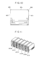
- Fig. 11 is a perspective view showing, as one example, a group of heads of a conventional ink jet color recording apparatus using inks different in density or consistency.
- a black (BK) ink head 311BK, a first cyanogen (C1) ink head 311C1, a second cyanogen (C2) ink head 311C2, a first Magenta (M1) ink head 311M1, a second Magenta (M2) ink head 311M2 and a yellow (Y) ink head 311Y are arranged in parallel.
- an ink suction/pressurization receiving means for removing bubbles in the interiors of the nozzles or for recovering the ink from the increasing viscosity due to its being left for a long time.
- One possible solution to these problems may be that a plurality of ink jet recording heads are formed integrally on the same substrate and disposed along the main scanning directions for conducting multivalued printing.
- a recording apparatus can be designed such that one type is used as each of yellow and black inks and two types are taken as each of Magenta and cyanogen inks, that is, six color inks are put to use.
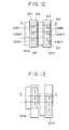
- Fig. 12 is an illustration of one example in which nozzles for six colors are disposed separately in two heads.
- a group of nozzles comprising a nozzle group 400Y for ejecting an yellow ink, a nozzle group 400M1 for ejecting a first Magenta ink and a nozzle group 400C1 for ejecting a first cyanogen ink is formed in a recess section 357 made in a face 356 of an orifice plate 403 attached to a head 301A.
- a group of nozzles comprising a nozzle group 400BK for ejecting a black ink, a nozzle group 400M2 for ejecting a second Magenta ink and a nozzle group 400C2 for ejecting a second cyanogen ink is formed in a recess section 357 made in a face 356 of an orifice plate 403 attached to a head 301B.
- the different inks to be mixed are adjacent to each other in the main scanning directions of printing.
- the yellow nozzle group and the black nozzle group assume an adjacent condition, and the two-color printing are required to be conduct simultaneously.
- nozzle groups discharging two different inks are disposed so as not to be adjacent to each other in the main scanning directions. That is, as shown in Fig. 13, a first nozzle of a nozzle group 200M1 of a head 301A and a first nozzle of a nozzle group 200M2 thereof are placed on a line A-A.
- a wasteful space 340 comes about in the head section so that the head itself increases in size to cause the size increase of the recording apparatus itself.
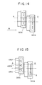
- the wasteful space is removed from the head in Fig. 13 as disclosed in Japanese Unexamined Patent Publication No. (HEI) 7-132619. That is, as shown in Fig. 14, the head 301A and the head 301B are disposed and density-different inks are used to enable high-quality multivalued color recording, and additionally, the nozzles of adjacent nozzle groups are disposed in a state shifted substantially by 1/2 of a nozzle pitch from each other in directions different from the main scanning directions to double the resolution for formation of a color image with a high gradation.
- HAI Japanese Unexamined Patent Publication No.
- a head 391B having a nozzle group holding only a black ink can accomplish higher-speed printing of a black image.
- a nozzle group 490Y of a head 391A for ejecting an yellow ink a nozzle group 490M thereof for ejecting a Magenta ink and a nozzle group 490C thereof for ejecting a cyanogen ink
- a color image is also printable.
- Fig. 16 is a perspective view showing a conventional orifice plate 403
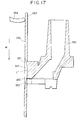
- Fig. 17 is a cross-sectional view showing the orifice plate 403, taken along a line B-B
- Fig. 18 is a cross-sectional view showing the orifice plate 403, taken along a line E-E.
- a recess section 357 which has a plurality of nozzles arranged therein.
- the recess section 357 has a recessed configuration comprising a curved surface formed by a combination or connection of a first surface 351 and a second surface 352 at the deepest portion L' of the recess section 357, and further comprising a third surface 353 and a fourth surface 354 provided on both sides of this curved surface.
- the first surface 351 forms a curved surface having a relatively steep inclination, whereas, in comparison with the first surface 351, the second surface 352 constitutes a gentler curved surface. Accordingly, the deepest portion L' where the first surface 351 and the second surface 352 are combined is positioned above a nozzle 400, that is, on the upstream side thereof in an arrow W direction indicative of a running direction of a blade 319 for wiping out an ink attached onto the recess section 357.
- a recording head using a member in which formed integrally are an orifice plate 403 having a number of common ink droplet discharging nozzles 400 and a top board 100 having groove portions forming ink passages corresponding respectively to the nozzles 400.
- ink jet recording apparatus employing such a recording head
- wet ink is attached onto the recess section 357 due to ink mist occurring when an ink is ejected from the recording head or due to satellite ink occurring at the refilling of the ink.
- the ink left at the suction can be attached to the recess section 357.
- This restoring unit is principally made up of a suction device for discharging ink forcedly from the nozzle 400 and a wiping device for wiping and cleaning the recess section 357.
- the wiping device is designed to make a blade 319, made from an elastic material or the like and shown in Fig. 19, come directly into contact with the face 356 and the recess section 357 and to make the blade 319 move relatively to slide on or rub against the face 356 and the recess section 357, thereby cleaning the plurality of nozzles 400 and the portions around them for securing the ejection stability.
- the entire face of the orifice plate composed of a conventional top board with grooves since there is a need for the face of the orifice plate composed of a conventional top board with grooves to be as thin as possible in the vicinity of the nozzles but for the entire face to be thick sufficient to increase its strength, naturally, the entire face does not have a flat configuration but it has a recess portion.
- the face in order to prevent the dries of the nozzles of the head, there is a need for the face to have a configuration to be covered with a cap installed commonly in a printer body; therefore, it is preferable that, in the face having the aforesaid recess portion, a part which comes into contact with the cap exists on the plane including a surface other than the recess portion.
- the recess section 357 is formed at a substantially central portion of the entire face 356.
- the pigment-based ink has large molecules and has a fixedly attaching property.
- the pigment ink left after wiped off can enter the nozzles due to the subsequent wiping operation by the blade, thereby causing an ejection-impossible condition.
- the residual or leavings after the wiping can also occur slightly around the nozzles 400, which can cause the deflection of ink ejected or the ejection-impossible condition.
- a conventional means to solve this problem relates to the improvement of the wiping way using a blade placed in the printer body. Since the ink used so far has been an dye ink, this conventional means has worked successfully. However, when a pigment ink is used for a higher resistance to light and higher concentration, further improvement becomes necessary.
- the blade 319 when sliding on the face 356 and the recess section 357, the blade 319 also slides simultaneously on a chip tank 302A and a chip tank 302B which have a flow passage for supplying the ink into a nozzle liquid chamber.
- the repetition of this operation can cause the ridgelines of the chip tanks 302A and 302B along the main scanning directions to damage the points A to D of the blade 319 as shown in Fig. 19.
- the point B of the blade 319 can induce the ink leavings on the head 301A while the point C thereof can induce the ink leavings on the head 301B; whereupon the nozzles 400 become a wet condition to lead to record contortion or ejection failure.
- a second object of this invention is to provide an ink jet recording head, an ink jet cartridge and an ink jet recording apparatus which are capable of maintaining an excellent condition even if a pigment ink is put to use.
- a third object of this invention is to provide an ink jet recording head, an ink jet cartridge and an ink jet recording apparatus which are capable of accomplishing less damages to a wiping blade.
- an ink jet recording head comprising a flat plate section having a recess section in its surface and an orifice plate having a plurality of openings made to eject a liquid and disposed linearly to be grouped in the recess section, with the surface of the flat plate section being cleaned by a cleaning member movable relative to the flat plate section in a direction perpendicular to a direction of the disposition of the ejecting openings in a state brought into contact with the surface of the flat plate section, wherein the recess section includes a combined curved surface made in a manner that a first curved surface having a first curvature and a second curved surface having a second curvature smaller than the first curvature are combined at a position corresponding to the deepest portion of the recess section so that the first curved surface is on the upstream side of the second curved surface in a cleaning direction of the cleaning member and made to extend in the disposition direction of the ejecting
- the ejecting opening group is formed in the vicinity of the deepest portion of the recess section made in the orifice plate, the depth of the recess section assumes the minimum needed, thus making no sharp angle with respect to first and second inclined surfaces forming both end portions of the combined curved surface. Accordingly, the angles made at areas connecting the combined curved surface and the first and second inclined surfaces become blunt so that the liquid is hard to stay after the cleaning by the cleaning member.
- the ejecting opening group is formed on the downstream side in the cleaning direction with respect to the deepest portion, that the surface in which the ejecting opening group is made is a general plane formed substantially perpendicularly to directions of liquid ejection by the ejecting openings, or that each of areas existing connectively between the first curved surface, the second curved surface, the two inclined surfaces and the general plane is formed as a smooth curved surface.
- the ink jet recording head according to this invention includes an equipment body formed integrally with the orifice plate in a state where the surface of the flat plate section is used as one of component surfaces.
- a radius of a curved surface formed on a first ridgeline portion defined by a surface, with which the cleaning member comes initially into contact with at the relative movement of the cleaning member, and the surface of the flat plate section to extend in a direction perpendicular substantially to the relatively moving direction of the cleaning member is below 0.1 mm, or that, in a second ridgeline portion defined by a surface including the recess section and a surface of the equipment body substantially perpendicular to the surface including recess section and substantially parallel with the relatively moving direction of the cleaning member, the radius of a curved surface formed on a portion on which the cleaning member slides at the relative movement is equal to or more than 0.2 mm.
- the radius of a curved surface formed on a corner portion of the equipment body defined by the first and second ridgeline portions is equal to or more than 0.2 mm, that the starting position of the curved surface of the second ridgeline portion is separated by more than 0.1 mm from the ejecting opening closest to the second ridgeline portion, or that the liquid is a pigment ink.
- the ink jet recording head according to this invention is equipped with an electrothermal converter for generating thermal energy to be used for ink ejection, or that the ink jet recording head is of a type that an ink is ejected from the ejecting openings utilizing the film boiling occurring in the ink due to thermal energy from an electrothermal converter.
- An ink jet cartridge according to this invention comprises the ink jet recording head according to this invention and a liquid container for holding an liquid to be supplied to the ink jet recording head.
- An ink jet recording apparatus comprises the ink jet cartridge according to this invention and a record medium conveying means for conveying a record medium onto which the liquid ejected from the ink jet recording head is adhered for recording.
- the ink jet recording apparatus comprises the aforesaid ink jet recording apparatus according to this invention and a cleaning member moved relatively in a direction perpendicular to an arranging direction of ejecting openings while being brought into contact with a surface of a flat plate section of the ink jet recording head to clean the surface of the flat plate section.
- the depth of the recess section becomes at the minimum needed so that the angles made with respect to the first and second inclined surfaces forming both the end portions of the combined curved surface do not become sharp. Accordingly, the angles of the areas between the combined curved surface and the first and second inclined surfaces become blunt so that the liquid is hard to stay, and even if a pigment ink, easy to fix, is used, it is possible to maintain an excellent ink ejection condition for a long time.
- first ridgeline portion, the second ridgeline portion and the corner portions of the equipment body formed integrally with the orifice plate are made to have a radius R, which enables less damage to the cleaning member and secures the certain cleaning of the recess section.
- Fig. 1 shows schematically a construction of a color ink jet recording apparatus according to a first embodiment of the present invention.
- a recording apparatus designated generally at reference numeral 100, is composed of a carriage 102 carrying two heads 101A and 101B and further detachably holding ink tanks 110A and 110B for supplying inks to the heads 101A and 101A, guide shafts 104 and 104 serving as a guide for the reciprocation of the carriage 102, a paper-feeding roller 107 for feeding record paper 106, a paper conveying roller 108 for conveying the record paper 106, and a blade 111 forming a component of a wiping device for restoring the printing functions of the heads 101A and 101B.
- the record paper 106 Upon receipt of a print signal from a non-shown host computer, the record paper 106 is fed by the paper conveying roller 108 and the paper feeding roller 107 to be set at a printing position. Subsequently, the heads 101A and 101B are released from a non-shown cap, and the carriage 102 carrying the heads 101A and 101B are moved to reciprocate along the guide shaft 104 and the guide shaft 105 to conduct a printing operation on the record paper 106.
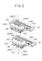
- a plurality of ejecting openings for discharging three kinds of inks namely, a yellow ink, a first Magenta (M1) ink and a first cyanogen (C1) ink, supplied from the ink tank 110A are disposed linearly to form nozzle groups 200Y, 200M1 and 200C1 (see Fig. 2).
- a plurality of ejecting openings for discharging a black (BK) ink, a second Magenta (M2) ink and a second cyanogen (C2) ink supplied from the ink tank 110B are disposed linearly to form nozzle groups 200BK, 200M2 and 200C2 (see Fig. 2).
- variable-density ink or different kinds of dyes can be put to use.
- heads 101A and 101B arranged have the same construction, it is also acceptable to use different kinds of heads, for instance, different in nozzle diameter.
- the ink tanks 110A and 110B are for storing the aforesaid color inks, and three kinds of inks are put in each of the ink tanks 110A and 110B.
- the ink tanks 110A and 110B are coupled to rubber seal portions (not shown) placed thereunder and further to stainless pipes or the like set in the heads 101A and 101B, respectively, so that the respective inks are supplied from the ink tanks 110A and 110B to the corresponding nozzles.
- the blade 111 is moved to slide on or rub against the ink ejecting surfaces of the heads 101A and 101B, thereby removing (wiping off) the residual ink on the ejecting surfaces.
- a chip tank 204 having an orifice plate 203 and a printed circuit board (PCB) 202 having a connector section 202a are fitted onto an aluminium-made base plate 201.
- a nozzle group 200Y for discharging an yellow ink
- a nozzle group 200M1 for ejecting a first Magenta ink
- a nozzle group 200C1 for ejecting a first cyanogen ink.
- a nozzle group 200M2 for ejecting a second Magenta ink
- a nozzle group 200C2 for ejecting a second cyanogen ink
- a nozzle group 200BK for ejecting a black ink.
- Each of nozzle group is made by disposing 48 nozzles linearly, and the respective nozzle groups are arranged at an interval more than the nozzle pitch.
- a non-shown ink passage is formed to supply each color ink, and for each of the nozzles, a non-shown electrothermal converter is provided to eject ink droplets.
- the electrothermal converter is heated to foam the ink so that the discharge of the ink droplets from each of the nozzles is controlled by that foaming force.
- the heads 101A and 101B are arranged in a state shifted from each other in a direction different from the main scanning direction for printing so as to form a step, with the step being established by shifting the heads 101A and 101B by a distance corresponding to the width of the nozzle group for one color plus the separation for partition between the nozzle groups in the direction different from the main scanning direction (see Fig. 4).
- the printed circuit board 202 is connected through its connector section 202a to a body side connector for receiving a power supply for the drive of the heads 101A and 101B for the ink ejection, a print signal and others.
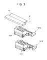
- Fig. 3 shows a state of wiping the heads 101A and 101B.
- the relative movement of the blade 111 with respect to the heads 101A and 101B accomplishes the wiping in a direction indicated by an arrow W.
- Fig. 4 is an illustration useful for explaining a disposing position of the heads 101A and 101B.
- the adjacent nozzles in the main scanning direction of the arrow W are arranged at positions along a line A-A, that is, they are disposed so that the first nozzle of the nozzle group 200M1 of the head 101A and the first nozzle of the nozzle group 200M2 of the head 101B coincide or are aligned with each other.
- the recess sections 157 of the heads 101A and 101B have the same configuration, and the description will be made representatively of only the head 101A.
- Fig. 5 is a perspective view showing the recess section 157 made in the face 156 of the orifice plate 203
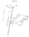
- Fig. 6 is a cross-sectional view showing the orifice plate 203, taken along a line C-C of Fig. 5
- Fig. 7 is a cross-sectional view of the orifice plate 203, taken along a line D-D of Fig. 5.
- reference character H represents a position of the location of an electrothermal converter which generates thermal energy to be used for the ink ejection.
- the recess section 157 has a concave configuration comprising a curved surface made by combining or coupling a first surface 151 and a second surface 152 at the deepest portion M of the recess section 157 as shown in Fig. 6, and further comprising third surface 153 and a fourth surface 154 formed both sides of this curved surface.
- the first surface 151 is formed as a curved surface having a gentler or slower curve, while, as compared with the first surface 151, the second surface 152 is formed as a curved surface having a relatively steep or high inclination. Accordingly, the deepest portion M at which the first surface 1512 and the second surface 152 are combined with each other is located under a central portion 158 of the recess section 157 made in the face 156, that is, on the downstream side of the central portion 158 in the arrow W indicative of the advancing direction of the blade 111.
- a flat fifth surface can also be formed at a portion of the connection of the first surface 151 and the second surface 152 to limit the angle of the recess section 157 with respect to the nozzles 200, which can more preferably secure the stabilization of the ejection of the ink.
- a curved surface is formed at the connection between the first surface 151, the second surface 152, the third surface 153, the fourth surface 154 and the fifth surface so as to prevent the occurrence of distinct bending points.
- the above-described construction can improve the configuration of the recess section 157 in depth, and can solve the two problems causing ink to be left after wiping, that is, the position of the deepest portion deeper than the nozzles 200 exists on the upstream side of the positions of the nozzles 200 in the blade advancing direction and the outcome is that the inclinations of both the sides (the conventional third surface 353 and the conventional fourth surface 354 in Fig. 16) of the recess section 157 become steep.
- the recess section 157 in this embodiment can offer the following effects.
- the recess section has a configuration equal or similar to that of the conventional recess section 357 in Fig. 17, in wiping by the blade 111, as compared with a single-cartridge construction, the advance and inclination of the blade 111 with respect to the recess section 357 are required to be set with higher precision.
- the recess section 157 in this embodiment improves the wiping ability of the blade 111 to the recess section 157, so that the margin on the advance and inclination of the blade 111 with respect to the recess section 157 increases considerably and the irregular wiping is eliminable, which permits the use in a high-speed high-image-quality printer.
- the recess section in this embodiment accomplishes less ink residual after wiping and permits the head to employ a pigment ink.
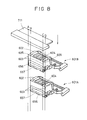
- Fig. 8 shows wiping states of heads 601A and 601B in a second embodiment of this invention
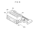
- Fig. 9 is an enlarged perspective illustration of an appearance of a chip tank 602 of the head 601A shown in Fig. 8.
- the heads 601A and 601B basically have the same construction as that of the head 101A or 101B in the first embodiment shown in Fig. 2, and the detailed description thereof will be omitted for brevity.
- a portion between points A and C of a blade 711 is first brought into contact with a front edge portion 604 forming a first ridgeline portion of a chip tank 602 of the head 601A and points A and C thereof are immediately brought into contact with front edge end portions 605 forming corner portions existing at both end portions of the front edge portion 604, respectively.
- the portion between the points A and C of the blade 711 wipes off the ink on a face 656 and a recess section 657 while the points A and C of the blade 711 slides a ridgeline 603 forming a second ridgeline portion.
- the point B instead of the point A and the point D in place of the point C are brought into contact with a front edge portion 604 forming a first ridgeline portion of a chip tank 602 of the head 601B to wipe off the ink on a face 656 and a recess section 657 while the blade 711 slides on a ridgeline 603 forming a second ridgeline portion, then terminating the wiping operation.
- the front edge portions 604, the front edge end portions 605 and the ridgelines 603 are formed to have a curved surface or roundness whose radius is R, thereby presenting a smooth configuration.
- each of the heads 601A and 601B can also be identical to that in the above-described first embodiment.
- chip tanks 602 of the head 601A and the head 601B have the same configuration.
- the width of the blade 711 is determined to wipe the recess section 657 holding the orifice nozzles, there is no need for the width to be larger than the length between the points A and D as shown in Fig. 8, and it is also possible that the width is larger than the length between the points B and C but smaller than the length between the points A and C.
- the ridgeline curved surface of the radius R to be formed on the front edge end portions 605 and the ridgelines 603 can be limited to only those with which the points B and C of the blade 711 come into contact.
- the chip tanks 602 are constructed such that a ridgeline curved surface whose radius is R is formed on the portions with or on which the blade 711 comes into contact or slides, that is, the front edge portions 604, the front edge end portions 605 and the ridgelines 603, which prevents the damages to the blade 711.
- the first to third study examples relate to a study about damages to the blade 711 and the record contortion and ejection failure which occurred in the actual printing when the radius R of the front edge end portions 603 and the ridgeline portion 603 was changed, while the fourth example relates to a study about these problems in the case in which the starting position of the ridgeline curved surface of the radius R on the ridgelines 603 was changed.
- the points A and B of the blade 711 was damaged or cut by the ridgeline 603 shown in Fig. 8.
- the guaranteed printing quantity of the main body was approximately fifty thousands, and the number of times of wiping was approximately two hundred thousands.
- the point A caused the ink residual on the head 601B after wiping, while the point B caused the ink residual on the head 601A after wiping; whereupon, the ejecting openings were wet and the record contortion or the ejection failure occurred.
- Table 2 shows the examination results on the damage to the blade 711 and the record contortion and the ejection failure in the actual printing in the case in which the value of the ridgeline curved surface radius R of the front edge end portion 605 was changed and the wiping operation was repeated two hundred thousands times.
- R[mm] 0.03 0.1 0.2 0.3 0.4 0.5 Print Result ⁇ ⁇ ⁇ ⁇ ⁇ ⁇ ⁇
- Table 3 shows the examination results about the record contortion and the ejection failure in the actual printing when the value of the ridgeline curved surface radius R of the front edge portion 604 was changed and the wiping operation was conducted in this radius R changing condition.
- R[mm] 0.03 0.05 0.1 0.2 0.3 0.4 Print Result ⁇ ⁇ ⁇ ⁇ ⁇ ⁇ ⁇
- a suction device for discharging an ink forcedly from the ejecting openings could not accomplish the suction because of no complete sealing so that difficulty was encountered in removing the ink attached onto the ejecting opening surface.
- the dust paper fuzz and others
- the viscosity-increasing ink ink after volatile components are evaporated
- Table 4 shows the examination results about the record contortion and the ejection failure in the actual printing in the case in which the starting position of the curved surface, whose radius is R, with respect to the end portion of the nozzle group was changed and the wiping operation was conducted in this starting position changing state.
- L1[mm] 0.03 0.05 0.1 0.2 0.3 0.4 Print Result ⁇ ⁇ ⁇ ⁇ ⁇ ⁇ ⁇
- the suction device can be sealed hermetically to secure sufficient suction so that the record contortion and the ejection failure are hard to occur.
- the damage to the blade 711 is substantially preventable so that it is possible to surely clean the portions around the ejecting openings by the wiping.
- the starting position of the curved surface of the radius R on the ridgelines 603 is set at a position separated by at least more than 0.1 mm from the end portion of the nozzle group, it is possible to certainly clean the portions around the ejecting openings by the suction device.
- An ink jet recording head in which a flat plate section has a recess section in its surface and an orifice plate having a plurality of openings grouped and disposed for ejecting a liquid is placed in the recess section, with the flat plate section being cleaned by a cleaning member movable perpendicularly to a direction of the disposition of the ejecting openings in a state brought into contact with a surface of the flat plate section.
- the recess section includes a combined curved surface made in a manner that a first curved surface having a first curvature and a second curved surface having a second curvature smaller than the first curvature are combined at a position corresponding to the deepest portion of the recess section.
- the first curved surface is located on the upstream side of the second curved surface in a cleaning direction of the cleaning member, and the combined curved surface extends in the disposition direction of said ejecting openings.
- the recess section further includes two inclined surfaces formed at both end portions of the combined curved surface to develop from the surface of the flat plate section. The two inclined surfaces are positioned to be separated by predetermined distances from both end portions of the grouped ejecting openings, respectively. This construction can reduce the ink residual on the recording head after the wiping by the cleaning member.
Landscapes
- Ink Jet (AREA)
- Particle Formation And Scattering Control In Inkjet Printers (AREA)
Applications Claiming Priority (2)
| Application Number | Priority Date | Filing Date | Title |
|---|---|---|---|
| JP30618198 | 1998-10-27 | ||
| JP10306181A JP2000127421A (ja) | 1998-10-27 | 1998-10-27 | インクジェット記録ヘッド、インクジェットカートリッジ及びインクジェット記録装置 |
Publications (2)
| Publication Number | Publication Date |
|---|---|
| EP0997283A2 true EP0997283A2 (de) | 2000-05-03 |
| EP0997283A3 EP0997283A3 (de) | 2000-11-29 |
Family
ID=17954016
Family Applications (1)
| Application Number | Title | Priority Date | Filing Date |
|---|---|---|---|
| EP99121307A Withdrawn EP0997283A3 (de) | 1998-10-27 | 1999-10-26 | Tintenstrahlaufzeichnungskopf, Tintenstrahlkassette und Tintenstrahlaufzeichnungsgerät |
Country Status (3)
| Country | Link |
|---|---|
| US (1) | US6375303B1 (de) |
| EP (1) | EP0997283A3 (de) |
| JP (1) | JP2000127421A (de) |
Families Citing this family (6)
| Publication number | Priority date | Publication date | Assignee | Title |
|---|---|---|---|---|
| US6652062B2 (en) * | 2000-03-31 | 2003-11-25 | Canon Kabushiki Kaisha | Liquid discharge recording head with orifice plate having extended portion fixed to recording head main body, liquid discharge recording apparatus having such head, and method for manufacturing such head |
| US7118189B2 (en) * | 2004-05-28 | 2006-10-10 | Videojet Technologies Inc. | Autopurge printing system |
| JP4983725B2 (ja) * | 2008-05-28 | 2012-07-25 | コニカミノルタホールディングス株式会社 | インクジェットヘッド |
| JP6144452B2 (ja) * | 2011-05-31 | 2017-06-07 | ブラザー工業株式会社 | インクジェット記録装置及びこれが有するインクジェットヘッドの製造方法 |
| JP5110213B2 (ja) * | 2012-04-26 | 2012-12-26 | コニカミノルタホールディングス株式会社 | インクジェットヘッド |
| JP6207216B2 (ja) * | 2013-04-25 | 2017-10-04 | キヤノン株式会社 | 液体吐出ヘッド |
Citations (1)
| Publication number | Priority date | Publication date | Assignee | Title |
|---|---|---|---|---|
| JPH07132619A (ja) | 1993-06-30 | 1995-05-23 | Canon Inc | カラーインクジェット記録装置 |
Family Cites Families (5)
| Publication number | Priority date | Publication date | Assignee | Title |
|---|---|---|---|---|
| DE69031666T2 (de) | 1989-01-13 | 1998-04-02 | Canon Kk | Tintenstrahlaufzeichnungskopf, Tintenstrahlaufzeichnungsgerät und Wischverfahren hierfür |
| ES2094746T3 (es) | 1989-09-18 | 1997-02-01 | Canon Kk | Aparato para chorros de tinta. |
| JP2667277B2 (ja) | 1990-03-14 | 1997-10-27 | キヤノン株式会社 | インクジェット記録装置 |
| JPH06134998A (ja) | 1992-10-22 | 1994-05-17 | Canon Inc | インクジェット記録装置 |
| US6164754A (en) | 1996-11-06 | 2000-12-26 | Canon Kabushiki Kaisha | Liquid discharging recording apparatus with elastic head cleaning member |
-
1998
- 1998-10-27 JP JP10306181A patent/JP2000127421A/ja active Pending
-
1999
- 1999-10-22 US US09/422,788 patent/US6375303B1/en not_active Expired - Fee Related
- 1999-10-26 EP EP99121307A patent/EP0997283A3/de not_active Withdrawn
Patent Citations (1)
| Publication number | Priority date | Publication date | Assignee | Title |
|---|---|---|---|---|
| JPH07132619A (ja) | 1993-06-30 | 1995-05-23 | Canon Inc | カラーインクジェット記録装置 |
Also Published As
| Publication number | Publication date |
|---|---|
| JP2000127421A (ja) | 2000-05-09 |
| US6375303B1 (en) | 2002-04-23 |
| EP0997283A3 (de) | 2000-11-29 |
Similar Documents
| Publication | Publication Date | Title |
|---|---|---|
| US6890056B2 (en) | Print cartridge servicing for an inkjet printing system using stationary print cartridges | |
| EP2033791B1 (de) | Flüssigkeitseinspritzkopfeinheit und Bilderzeugungsvorrichtung | |
| JP2901361B2 (ja) | インクジェット記録装置 | |
| US20010003459A1 (en) | Liquid discharge apparatus | |
| JP2009023118A (ja) | インクジェット記録ヘッドのワイピング方法 | |
| US7097275B2 (en) | Single actuation axis printhead cleaner architecture for staggered printheads | |
| EP1902848A2 (de) | Tintenstrahldrucker und Druckverfahren damit | |
| US6375303B1 (en) | Ink jet recording head, ink jet cartridge and ink jet recording apparatus | |
| US8882244B2 (en) | Image forming apparatus | |
| EP0847872A1 (de) | Tintenstrahldruckverfahren, das eine erste und eine zweite Flüssigkeit verwendet, und eine Druckvorrichtung für dieses Verfahren | |
| US6547369B1 (en) | Layered cleaning blade and image forming device arranged with the same | |
| US20020057317A1 (en) | Ink container configured for use with printer | |
| JP3234087B2 (ja) | インクジェット記録装置 | |
| US6929347B2 (en) | Ink jet printing apparatus and wiping method therefor | |
| US6499824B1 (en) | Ink jet recording apparatus with dedicated wiping members | |
| JPH09141841A (ja) | インクジェットプリンタ | |
| JP4035213B2 (ja) | インクジェット記録装置および方法 | |
| US6126282A (en) | Ink-jet recording apparatus and method thereof | |
| JPH106533A (ja) | プリント装置および該装置の制御方法 | |
| JPH1178039A (ja) | インクジェット記録装置 | |
| JPH10235894A (ja) | インクジェット記録装置 | |
| KR100547160B1 (ko) | 잉크젯 프린터 | |
| JPH1076648A (ja) | インクジェット記録ヘッド及びインクジェット記録方法 | |
| KR19990040863A (ko) | 잉크젯 프린트헤드 카트리지의 고속 인쇄 장치 | |
| JP2860685B2 (ja) | インクジェット記録装置の回復方法 |
Legal Events
| Date | Code | Title | Description |
|---|---|---|---|
| PUAI | Public reference made under article 153(3) epc to a published international application that has entered the european phase |
Free format text: ORIGINAL CODE: 0009012 |
|
| AK | Designated contracting states |
Kind code of ref document: A2 Designated state(s): DE ES FR GB IT NL |
|
| AX | Request for extension of the european patent |
Free format text: AL;LT;LV;MK;RO;SI |
|
| PUAL | Search report despatched |
Free format text: ORIGINAL CODE: 0009013 |
|
| AK | Designated contracting states |
Kind code of ref document: A3 Designated state(s): AT BE CH CY DE DK ES FI FR GB GR IE IT LI LU MC NL PT SE |
|
| AX | Request for extension of the european patent |
Free format text: AL;LT;LV;MK;RO;SI |
|
| 17P | Request for examination filed |
Effective date: 20010412 |
|
| AKX | Designation fees paid |
Free format text: DE ES FR GB IT NL |
|
| 17Q | First examination report despatched |
Effective date: 20071025 |
|
| STAA | Information on the status of an ep patent application or granted ep patent |
Free format text: STATUS: THE APPLICATION HAS BEEN WITHDRAWN |
|
| 18W | Application withdrawn |
Effective date: 20080229 |