EP0997348A2 - Kabelverteilungselement und Verteilungskonfiguration - Google Patents
Kabelverteilungselement und Verteilungskonfiguration Download PDFInfo
- Publication number
- EP0997348A2 EP0997348A2 EP99307330A EP99307330A EP0997348A2 EP 0997348 A2 EP0997348 A2 EP 0997348A2 EP 99307330 A EP99307330 A EP 99307330A EP 99307330 A EP99307330 A EP 99307330A EP 0997348 A2 EP0997348 A2 EP 0997348A2
- Authority
- EP
- European Patent Office
- Prior art keywords
- wire distribution
- electrical conductors
- wires
- distribution member
- electrical
- Prior art date
- Legal status (The legal status is an assumption and is not a legal conclusion. Google has not performed a legal analysis and makes no representation as to the accuracy of the status listed.)
- Withdrawn
Links
- 239000012777 electrically insulating material Substances 0.000 claims 1
- 239000004020 conductor Substances 0.000 abstract description 70
- 239000000758 substrate Substances 0.000 description 4
- 239000011810 insulating material Substances 0.000 description 2
- 238000003466 welding Methods 0.000 description 2
- 235000001674 Agaricus brunnescens Nutrition 0.000 description 1
- 239000000853 adhesive Substances 0.000 description 1
- 238000005452 bending Methods 0.000 description 1
- 230000005611 electricity Effects 0.000 description 1
Images


Classifications
-
- B—PERFORMING OPERATIONS; TRANSPORTING
- B60—VEHICLES IN GENERAL
- B60R—VEHICLES, VEHICLE FITTINGS, OR VEHICLE PARTS, NOT OTHERWISE PROVIDED FOR
- B60R16/00—Electric or fluid circuits specially adapted for vehicles and not otherwise provided for; Arrangement of elements of electric or fluid circuits specially adapted for vehicles and not otherwise provided for
- B60R16/02—Electric or fluid circuits specially adapted for vehicles and not otherwise provided for; Arrangement of elements of electric or fluid circuits specially adapted for vehicles and not otherwise provided for electric constitutive elements
- B60R16/0207—Wire harnesses
- B60R16/0215—Protecting, fastening and routing means therefor
Definitions
- the present invention relates to a distribution member for electrical wires.
- a wire distribution configuration of a combination lamp of an automobile is described in JP-9-231814.
- a plurality of bulbs are provided in prescribed locations of a body, and a connector member is provided which supplies electricity to the bulbs.
- a wire distribution circuit which passes along a prescribed path to each bulb and the connector member.
- the wire distribution circuit consists of an electric wire which connects terminal fittings connected to the bulbs, and an electric wire which connects bulb terminal fittings and connector member terminal fittings. These electric wires are distributed along the body, the terminal fittings being attached to both ends of these electric wires.
- a wire distribution member comprising a plurality of substantially rigid and individual electrical wires arranged in a predetermined pattern, and a connecting member holding said wires in said pattern whereby exposed portions of said wires are adapted for connection to a fixed array of electrical components.
- the connecting member comprises a sheet having apertures or recesses in which said wires are revealed.
- the wires are preferably bare and the connecting member of insulating material.
- the wires are sandwiched between adjacent sheets.
- the wires preferably do not make electrical contact.
- the connecting member may include positioning means such as one or more apertures to locate the wire distribution member with respect to a substrate such as a fixed array of electrical components.
- the wires may locate the distribution member.
- the connecting member may further include fixing means to fix the distribution member with respect to a substrate.
- fixing means are preferably also positioning means and may comprise an aperture of the connecting member for co-operation with a screw or upstanding projection.
- one or more wires may be fixed to a substrate by e.g. bending in or around an abutment of the substrate.
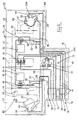
- the present embodiment is suitable for a combination lamp 10 provided in a cabin roof of an automobile.
- the combination lamp 10 comprises a plastic body 11, a plurality of bulbs 50 attached to the body 11, a plurality of switches 30 and 31 fixed to the body 11, and a connector member 16 formed in the body 11.
- Located to the left, right and posterior sides of supporting plate members 12 of the body 11 are three covers 13 and 14, lower faces of which are open. These covers 13 and 14 protrude in a square shape above the supporting plate members 12, the bulbs 50 being covered by these.
- Attachment holes 22 for attaching the bulbs 50 pass through upper faces of the covers 13 and 14.
- the upper faces of the covers 13 and 14 are all of the same height, and a wire distribution member 40 in a distributed state is attached onto it.
- Protrusions 15 are formed on the upper faces of the covers 13 and 14 for fixing the position of the wire distribution member 40.
- the directions anterior, posterior, left, and right are used relative to Figure 3.
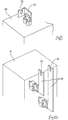
- the connector member 16 is formed on side faces of one of the covers 13 and the cover 14.
- the connector member 16 comprises: a receiving plate member 17 having the same height as the supporting plate member 12; supporting wall faces 18 which protrude upwards from the posterior and anterior sides of the receiving plate member 17; and a dividing wall 19 which protrudes upwards at a central position relative to the anterior-posterior direction of the receiving plate member 17.
- Anterior and posterior fining spaces 20 are formed between the supporting wall faces 18 and the dividing wall 19, side faces and upper faces of these spaces 20 being open.
- Corresponding connectors 60 of a wire harness attached to a battery (not shown) are fitted in these spaces 20.
- Position fixing holes 21 pass through the receiving plate member 17 between upper and lower faces thereof, and electrical conductors 41 fit therein.
- the corresponding connector 60 comprises a housing 61 which fits in the spaces 20, and a plurality (seven in the present embodiment) of feeder terminal fittings 62 inserted into the housing 61.
- a cut-away 64 is formed on a lower face of the housing 61, this cut-away 64 allowing a resilient contact member 63 formed on a lower face of a feeder terminal fitting 62 to protrude towards the receiving plate member 17.
- the electrical conductors 41 are clamped between the resilient contact member 63 and the receiving plate member 17.
- a locking arm 65 is formed on an upper face of the housing 61. This locking arm 65 fits with a locking protrusion 19A formed on an upper edge of the dividing wall 19 and thereby latches the corresponding connector 60 and the fining members 20 in a fitted state.
- Three switches 30 and 31 aligned from left to right are fixed to an upper face of the supporting plate member 12. Lower faces of these switches 30 and 31 (the faces close to the interior of the automobile) have slide-type or push-type operating members (not shown). Operating these operating members switches on a light inside the automobile or turns on a map lamp.
- Three terminal fittings 32 are provided on an upper face of the central switch 30, and a pressure contact slit 33 provided in each terminal fitting 32 allows the electrical conductor 41 to be inserted therein from above.
- the switches 31 positioned to the left and right each have two terminal fittings 34 provided on a side face, a pressure contact slit 35 being provided in each terminal fitting 34 to allow the electrical conductor 41 to be inserted from above.
- the left and right covers 13 and the posterior cover 14 are linked by linking members 23, these linking members 23 being positioned at left and right ends of an anterior edge of the posterior cover 14 and having the same height as the upper face thereof Upper faces of these linking members 23 are provided with terminal fittings 24 which are L-shaped when viewed from above, both edges of each terminal fitting 24 having pressure contact slits 25 which allow the electrical conductor 41 to be inserted therein from above (see Figure 6).
- Long and thin terminal fittings 26 are provided at three locations, the left and right edges and the centre, of the anterior edge portion of the posterior cover 14, these terminal fittings 26 being sunk into the upper face of the cover 14 with portions thereof protruding.
- the protruding portions of the terminal fittings 26 have pressure contact slits 27 which allow the electrical conductor 41 to be inserted therein from above.
- the wire distribution member 40 which is attached to the combination lamp 10 will be explained.
- the wire distribution member 40 comprises the plurality of electrical conductors 41 and two sheet-like wrapping members 42.
- the electrical conductors 41 consist of electrically conductive single wires which have a relatively wide diameter and therefore a degree of rigidity whereby they cannot readily bend (a degree of rigidity whereby they maintain their own shape independently).
- the outer circumference of each electrical conductor 41 is not provided with an insulating covering, and is in a state in which electrically conducting faces are exposed.
- the electrical conductors 41 are bent along a prescribed wire distribution path in the vicinity of the connector member 16 and the attachment holes 22 of the bulbs 50, and connect the terminal fittings 32 and 34 of the switches 30 and 31 and the independent terminal fittings 24 and 26.
- the electrical conductors 41 bent along this prescribed path are distributed above one of the wrapping members 42, and the other wrapping member 42 is provided on top so that the electrical conductors 41 are covered in a state whereby they are clamped tightly between the two wrapping members 42.
- the electrical conductors 41 and the wrapping members 42 are fixed by being bonded mutually together by an adhesive agent and are also fixed by welding.
- the wrapping members 42 are translucent (this includes both transparency or semi-transparency), and therefore it is possible to visually verify the wire distribution path of the electrical conductors 41 which have been clamped.
- the wrapping members 42 are composed of insulating material, and consequently this prevents the short-circuiting of the electrical conductors 41 within the area of their having been clamped by the wrapping members 42.
- wrapping members 42 of the wire distribution member 40 although covering the wire distribution area of the electrical conductors 41, are as small as possible. Furthermore, three fixing holes 43 are formed on the wrapping members 42 at positions which correspond to the protrusions 15 of the covers 13 and 14.
- the electrical conductors 41 are exposed from the wrapping members 42 at a position close to the connector member 16, as well as at the attaching positions of the bulbs 50, the attaching positions of the terminal fittings 32 and 34 of the switches 30 and 31, and the attaching positions of the independent terminal fittings 24 and 26. When this exposure is located at the outer edge of the wrapping members 42, a retreating edge 44 allow the ends of the electrical conductors 41 to be exposed.
- the anterior end portion of the electrical conductors 41 which extend along the receiving plate member 17 are bent downwards and form position fixing members 41A.
- This wire distribution member 40 is attached to the body 11 from above. When this attachment takes place, the protrusions 15 are fitted with the fixing holes 43 and the wire distribution member 40 is positioned over the covers 13 and 14 and the upper faces of the linking members 23.
- the portions of the electrical conductors 41 which protrude from the wrapping members 42 are positioned at the upper edges of the pressure contact slits 25, 27, 33 and 35 of the terminal fittings 24, 26, 32 and 34, and the electrical conductors 41 near these pressure contact slits 25, 27, 33 and 35 are driven or pushed therein and fit therewith. As a result, the terminal fittings 24, 26, 32 and 34 and the electrical conductors 41 reach a conducting state.
- portions of the electrical conductors 41 which protrude from the wrapping members 42 are positioned along upper face circumference edges of the attachment holes 22 of the bulbs 50. Consequently, these portions of the electrical conductors 41 come from lower face sides of joining protrusions 52 of bulb holders 51, pass along recesses 22A of the attachment holes 22 and pass through to the upper face side when the bulbs 50 are rotated, the electrical conductors 41 are resiliently clamped between resilient contacting members 53 which are provided at the lower face of the joining protrusions 52 and the upper face circumference edges of the attachment holes 22, and the bulbs 50 and the electrical conductors 41 thereby reach a conducting state (see Figure 5).
- the position fixing members 41A at the anterior ends of the electrical conductors 41 on the connector member 16 fit with the position fixing holes 21, the anterior ends of the position fixing members 41A protruding beyond the lower face of the receiving plate member 17.
- These protruding position fixing members 41A are bent so as to extend along the lower face of the receiving plate member 17 and thereby regulate their removal from the position fixing holes 21 (see Figure 8).
- each electrical conductor 41 is fixed to the body 11 in a prescribed position and in a state whereby its position is fixed, and then the feeder terminal fitting 62 of the corresponding connector 60 is attached. That is, the attachment of the wire distribution member 40 to the body 11, as described above, has been completed.
- the corresponding connector 60 is fitted to the connector member 16, and the resilient contact member 63 of the feeder terminal fitting 62 makes resilient contact with the electrical conductor 41.
- This resilient contact is effected by clamping the electrical conductor 41 between the resilient contact member 63 and the receiving plate member 17.
- the feeder terminal fitting 62 and the electrical conductor 41 thereby reach a conducting state.
- the wire distribution member 40 which comprises the wire distribution path of the combination lamp 10 is configured with a plurality of electrical conductors 41 being clamped in a unified manner between wrapping members 42, all of the electrical conductors 41 can be set simultaneously and, as a result, operability is improved compared to the case in which each electrical conductor 41 is attached to the body 11 one at a time. Accordingly, management and handling are easier.
- these electrical conductors 41 have a degree of rigidity whereby they maintain their own shape independently. Consequently, all of the electrical conductors 41 can be fixed in position along the prescribed wire distribution path merely by fixing the wrapping members 42 to three positions on the upper faces of the covers 13 and 14 and by fixing the position of a portion of the electrical conductor 41 relative to the connector member 16. As a result, all of the electrical conductors 41 can be maintained in a distributed state along the prescribed wire distribution path without fixing the position of these electrical conductors 41 individually.
- the wrapping members 42 are translucent and, consequently, the operator can visually verify the wire distribution path of the electrical conductors 41 at the time when the wire distribution operation within the body 11 is being performed. Fixing the direction and position of the wire distribution member 40 relative to the body 11 is thereby simplified and operability is improved.
- the electrical conductors 41 are bare wires, the outer circumferences of which are in an exposed and conducting state. However these electrical conductors 41 are distributed in a manner whereby they do not make mutual contact, and the wrapping members 42 are electrically insulated. As a result, short-circuiting of the electrical conductors 41 is avoided.
- the electrical conductors 41 do not require an insulating covering, and the issues arising from having a covering, that is, an increase in the diameter of the electrical conductors 41 (an increase in the thickness of the wire distribution member 40) and an increase in cost, are avoided.
- the position fixing members 41A of the electrical conductors 41 in the connector member 16 are inserted into the position fixing holes 21 and thereby maintain the electrical conductors 41 in a fixed position on the upper face of the receiving plate member 17, and the electrical conductors 41 make direct contact with the feeder terminal fittings 62.
- the connector member 16 does not require terminal fittings to connect with the feeder terminal fittings 62 and, accordingly, the configuration is simplified and the number of components reduced.
- the position fixing means utilises holes and ends of the electrical conductors are bent and inserted therein.
- the electrical conductors are inserted into the holes without being bent, and that the electrical conductors are maintained in position by applying heat and thereby changing the shape of protrusions formed on the connector member.
Landscapes
- Engineering & Computer Science (AREA)
- Mechanical Engineering (AREA)
- Installation Of Indoor Wiring (AREA)
- Arrangement Of Elements, Cooling, Sealing, Or The Like Of Lighting Devices (AREA)
- Insulated Conductors (AREA)
- Insulating Bodies (AREA)
- Coupling Device And Connection With Printed Circuit (AREA)
Applications Claiming Priority (2)
| Application Number | Priority Date | Filing Date | Title |
|---|---|---|---|
| JP30797098 | 1998-10-29 | ||
| JP10307970A JP2000133052A (ja) | 1998-10-29 | 1998-10-29 | 配線部材及び配線構造 |
Publications (2)
| Publication Number | Publication Date |
|---|---|
| EP0997348A2 true EP0997348A2 (de) | 2000-05-03 |
| EP0997348A3 EP0997348A3 (de) | 2003-09-03 |
Family
ID=17975364
Family Applications (1)
| Application Number | Title | Priority Date | Filing Date |
|---|---|---|---|
| EP99307330A Withdrawn EP0997348A3 (de) | 1998-10-29 | 1999-09-15 | Kabelverteilungselement und Verteilungskonfiguration |
Country Status (4)
| Country | Link |
|---|---|
| US (1) | US6407337B1 (de) |
| EP (1) | EP0997348A3 (de) |
| JP (1) | JP2000133052A (de) |
| CN (1) | CN1175537C (de) |
Cited By (1)
| Publication number | Priority date | Publication date | Assignee | Title |
|---|---|---|---|---|
| CN111976620A (zh) * | 2020-07-29 | 2020-11-24 | 泰州市博泰电子有限公司 | 一种新能源汽车用线束防水密封件 |
Families Citing this family (6)
| Publication number | Priority date | Publication date | Assignee | Title |
|---|---|---|---|---|
| JP6079321B2 (ja) * | 2013-03-08 | 2017-02-15 | 住友電装株式会社 | 配線モジュール及び配線モジュールの組付方法 |
| JP6417349B2 (ja) * | 2016-03-09 | 2018-11-07 | 矢崎総業株式会社 | コネクタモジュール及び液圧制御装置 |
| JP7087348B2 (ja) * | 2017-11-08 | 2022-06-21 | 株式会社オートネットワーク技術研究所 | バスバーモジュール及びバスバー |
| JP7392406B2 (ja) * | 2019-11-14 | 2023-12-06 | 住友電装株式会社 | 配線部材 |
| JP7419920B2 (ja) * | 2020-03-26 | 2024-01-23 | 株式会社オートネットワーク技術研究所 | 配線部材 |
| JP7371557B2 (ja) * | 2020-03-31 | 2023-10-31 | 住友電装株式会社 | 配線部材 |
Citations (1)
| Publication number | Priority date | Publication date | Assignee | Title |
|---|---|---|---|---|
| JPH09231814A (ja) | 1996-02-26 | 1997-09-05 | Koito Mfg Co Ltd | 車輌用灯具 |
Family Cites Families (9)
| Publication number | Priority date | Publication date | Assignee | Title |
|---|---|---|---|---|
| US2903502A (en) * | 1955-11-21 | 1959-09-08 | Burroughs Corp | Controlled spacing signal wire distribution system |
| US3697767A (en) * | 1970-02-12 | 1972-10-10 | Carrozzeria Pininfarina Soc Pe | Electric energy distribution systems |
| US4335269A (en) * | 1980-09-19 | 1982-06-15 | H. H. Robertson Company | Isolator device and wire distributing system utilizing the same |
| US4820189A (en) * | 1987-12-17 | 1989-04-11 | Amp Incorporated | Method and apparatus for electrical wiring of structural assemblies |
| FR2640563B1 (fr) * | 1988-12-16 | 1993-07-02 | Peugeot | Appui de cric pour vehicule automobile |
| US5012391A (en) * | 1989-08-17 | 1991-04-30 | Amp Incorporated | Molded electrical interconnection system |
| US5097592A (en) * | 1989-08-17 | 1992-03-24 | Amp Incorporated | Method of making molded electrical interconnection system |
| EP0595001B1 (de) * | 1992-10-30 | 1997-02-26 | Daimler-Benz Aktiengesellschaft | Kabelanordnung |
| US6184474B1 (en) * | 1998-10-23 | 2001-02-06 | Lucent Technologies Inc. | Device for managing wire and cable for electronic systems |
-
1998
- 1998-10-29 JP JP10307970A patent/JP2000133052A/ja not_active Abandoned
-
1999
- 1999-09-15 EP EP99307330A patent/EP0997348A3/de not_active Withdrawn
- 1999-10-05 US US09/412,317 patent/US6407337B1/en not_active Expired - Fee Related
- 1999-10-28 CN CNB991220900A patent/CN1175537C/zh not_active Expired - Fee Related
Patent Citations (1)
| Publication number | Priority date | Publication date | Assignee | Title |
|---|---|---|---|---|
| JPH09231814A (ja) | 1996-02-26 | 1997-09-05 | Koito Mfg Co Ltd | 車輌用灯具 |
Cited By (1)
| Publication number | Priority date | Publication date | Assignee | Title |
|---|---|---|---|---|
| CN111976620A (zh) * | 2020-07-29 | 2020-11-24 | 泰州市博泰电子有限公司 | 一种新能源汽车用线束防水密封件 |
Also Published As
| Publication number | Publication date |
|---|---|
| JP2000133052A (ja) | 2000-05-12 |
| CN1175537C (zh) | 2004-11-10 |
| CN1253403A (zh) | 2000-05-17 |
| EP0997348A3 (de) | 2003-09-03 |
| US6407337B1 (en) | 2002-06-18 |
Similar Documents
| Publication | Publication Date | Title |
|---|---|---|
| US9722338B2 (en) | Electric cable structural body, electric connection structure, and method for producing electric cable structural body | |
| EP1124287B1 (de) | Elektrischer Verbindungskontakt | |
| EP0961351A2 (de) | Verbinder für flexible-Schaltplatte | |
| CN1124942A (zh) | 复合式联接器 | |
| EP1006615B1 (de) | Elektrischen Verbindung Anordnung | |
| US8449316B2 (en) | Press-contacting connection structure of electric wire | |
| US6407337B1 (en) | Wire distribution member and wire distribution configuration | |
| JPH10129370A (ja) | 天井用電装組立体 | |
| JPH02312174A (ja) | フレキシブルな回路接続装置 | |
| EP1180815B1 (de) | Verbindungsstruktur von elektrischen Drähten einer Lampeneinheit | |
| US6461027B1 (en) | Rear combination lamp | |
| US9017094B2 (en) | Coupling structure for a flat wiring cable having non-uniform pitch | |
| US6123553A (en) | Branch junction box assembly | |
| US6290380B1 (en) | Vehicle lamp unit | |
| JP3890389B2 (ja) | シート状配線部材 | |
| US6083012A (en) | Rear combination lamp | |
| KR20030028760A (ko) | 단락 전기 커넥터 | |
| JP4201445B2 (ja) | リアコンビネーションランプ | |
| US6319014B1 (en) | Holder for the securing of a sun visor | |
| CN102640362A (zh) | 电连接件 | |
| KR102883816B1 (ko) | 직렬 회로패턴 타입의 인터락 조인트 커넥터 | |
| US20070190849A1 (en) | Lamp unit | |
| JP2861669B2 (ja) | 自動車用灯具におけるフレキシブルプリント配線板接続構造 | |
| JPH07245130A (ja) | フラットケーブル用ジョイントボックス | |
| CN218033054U (zh) | 一种led线槽灯的中继连接头和中继连接结构 |
Legal Events
| Date | Code | Title | Description |
|---|---|---|---|
| PUAI | Public reference made under article 153(3) epc to a published international application that has entered the european phase |
Free format text: ORIGINAL CODE: 0009012 |
|
| 17P | Request for examination filed |
Effective date: 19991001 |
|
| AK | Designated contracting states |
Kind code of ref document: A2 Designated state(s): AT BE CH CY DE DK ES FI FR GB GR IE IT LI LU MC NL PT SE |
|
| AX | Request for extension of the european patent |
Free format text: AL;LT;LV;MK;RO;SI |
|
| PUAL | Search report despatched |
Free format text: ORIGINAL CODE: 0009013 |
|
| AK | Designated contracting states |
Kind code of ref document: A3 Designated state(s): AT BE CH CY DE DK ES FI FR GB GR IE IT LI LU MC NL PT SE |
|
| AX | Request for extension of the european patent |
Extension state: AL LT LV MK RO SI |
|
| AKX | Designation fees paid |
Designated state(s): DE FR GB IT |
|
| 17Q | First examination report despatched |
Effective date: 20040705 |
|
| STAA | Information on the status of an ep patent application or granted ep patent |
Free format text: STATUS: THE APPLICATION IS DEEMED TO BE WITHDRAWN |
|
| 18D | Application deemed to be withdrawn |
Effective date: 20041116 |