EP0997351B1 - Trenn- und/oder Rückhaltevorrichtung für Fahrzeuge, wie für Kombinationskraftwagen od. dgl. - Google Patents
Trenn- und/oder Rückhaltevorrichtung für Fahrzeuge, wie für Kombinationskraftwagen od. dgl. Download PDFInfo
- Publication number
- EP0997351B1 EP0997351B1 EP19990120420 EP99120420A EP0997351B1 EP 0997351 B1 EP0997351 B1 EP 0997351B1 EP 19990120420 EP19990120420 EP 19990120420 EP 99120420 A EP99120420 A EP 99120420A EP 0997351 B1 EP0997351 B1 EP 0997351B1
- Authority
- EP
- European Patent Office
- Prior art keywords
- plug
- funnel
- separating
- holding bar
- restraining device
- Prior art date
- Legal status (The legal status is an assumption and is not a legal conclusion. Google has not performed a legal analysis and makes no representation as to the accuracy of the status listed.)
- Expired - Lifetime
Links
- 238000000926 separation method Methods 0.000 title description 2
- 239000002184 metal Substances 0.000 claims description 6
- 230000000295 complement effect Effects 0.000 claims description 3
- 230000000452 restraining effect Effects 0.000 claims 11
- 238000010276 construction Methods 0.000 claims 4
- 239000000463 material Substances 0.000 claims 1
- 238000003780 insertion Methods 0.000 description 15
- 230000037431 insertion Effects 0.000 description 15
- 230000000875 corresponding effect Effects 0.000 description 5
- 210000003128 head Anatomy 0.000 description 3
- 230000006835 compression Effects 0.000 description 2
- 238000007906 compression Methods 0.000 description 2
- 238000004804 winding Methods 0.000 description 2
- 230000002596 correlated effect Effects 0.000 description 1
- 238000006073 displacement reaction Methods 0.000 description 1
- 238000002347 injection Methods 0.000 description 1
- 239000007924 injection Substances 0.000 description 1
- 230000014759 maintenance of location Effects 0.000 description 1
- 239000011159 matrix material Substances 0.000 description 1
- 230000004048 modification Effects 0.000 description 1
- 238000012986 modification Methods 0.000 description 1
- 239000000725 suspension Substances 0.000 description 1
- 238000011144 upstream manufacturing Methods 0.000 description 1
Images
Classifications
-
- B—PERFORMING OPERATIONS; TRANSPORTING
- B60—VEHICLES IN GENERAL
- B60P—VEHICLES ADAPTED FOR LOAD TRANSPORTATION OR TO TRANSPORT, TO CARRY, OR TO COMPRISE SPECIAL LOADS OR OBJECTS
- B60P7/00—Securing or covering of load on vehicles
- B60P7/06—Securing of load
- B60P7/135—Securing or supporting by load bracing means
- B60P7/15—Securing or supporting by load bracing means the load bracing means comprising a movable bar
-
- B—PERFORMING OPERATIONS; TRANSPORTING
- B60—VEHICLES IN GENERAL
- B60R—VEHICLES, VEHICLE FITTINGS, OR VEHICLE PARTS, NOT OTHERWISE PROVIDED FOR
- B60R21/00—Arrangements or fittings on vehicles for protecting or preventing injuries to occupants or pedestrians in case of accidents or other traffic risks
- B60R21/02—Occupant safety arrangements or fittings, e.g. crash pads
- B60R21/06—Safety nets, transparent sheets, curtains, or the like, e.g. between occupants and glass
Definitions
- the invention relates to a separating and / or retaining device for vehicles, such as for combination vehicles or the like, according to the preamble of Claim 1.
- the known restraint device described above according to DE 40 10 209 C2 has a horizontal and across the direction of travel behind the rear seat backrests Combination car built-in mounting bracket on.
- the mounting bracket forms a roller blind housing a winding shaft for receiving a network path, which attached with its inner edge to the winding shaft and against a driving torque, here a wound Spring motor, vertically extendable and in the extended position Operating position can be fastened on the vehicle side.
- the outer Edge of the network track a supporting bar carrying the latter on, in the longitudinal direction of the handrail for tolerance reasons axially displaceable support rod ends each at an angle to a male head-shaped Plug element are deformed.
- DE 39 38 776 C1 is one of a roller blind housing horizontal pull-out load compartment cover known, those arranged on the outer edge of the cover sheet Handrail also two shaped like a male head Handrail ends forms.
- the handlebar ends work however, not with vehicle-shaped die-shaped ones Plug elements together, but rather with one Hanging part that has a hook-shaped section with a Has hook opening facing away from the roller blind housing.
- Each hook opening is for easy hooking an insertion funnel slotted on the funnel jacket side connected upstream, the opening of the funnel to the roller blind housing is facing and the top of the funnel the hook opening of the hanging part ends.
- the invention based on the task, the known restraint to develop further so that this is an uncomplicated Attachment of the handlebar ends to the assigned vehicle-side attachment points allowed.
- the vehicle-side attachment point accordingly points one in the insertion direction of the associated handlebar end narrowing introductory funnel on the preferably a substantially closed revolving Has funnel jacket.
- the funnel opening is the receptacle bracket, e.g. the blind housing.
- a plug element is arranged on the funnel bottom, which also points to the holder.
- the one formed by the associated handlebar end Plug element is a translationally movable one Locking element assigned, which at least indirectly guided on or at the end of the handlebar and is spring-loaded into its locking position and which is assigned an operating handle on the handlebar side is.
- the separation and / or retention device according to the invention allows a convenient attachment of the two Holding rod ends.
- the attachment is such that the subject Handrail end into the funnel-shaped insertion opening used and at the bottom of the funnel in one such measures is continued until the male-shaped and the female plug-in element with each other lock.
- the Holding rod assigned an operating handle.
- the deepest funnel of the introductory funnel protrudes the deepest funnel of the introductory funnel as a male-shaped one Plug-in element a plug eyelet in the direction of the holder, e.g. towards the blind housing, in front.
- the plug eyelet expediently adjusts from a vehicle side attached sheet metal part bent out tongue-like
- the male-like plug eyelet works a matrix-like, arranged at the end of the handrail, sleeve or sleeve-shaped component together, which also spring-loaded into its locking position Bolt or the bolt part or the bolt element contains.
- plug elements are from Basically, buckles for vehicle seat belts known and for example in the DE 30 08 298 C2 described.
- Deepest funnel of the insertion funnel as a matrix-like Plug-in element approximately at right angles to the funnel axis extending recess provided which is in the locking position the plug connection of a hook-shaped Handrail end is gripped behind.
- the locking element forms a sliding lock, which on the jacket surface facing away from the hook surface the support rod engages the latter in the latching opening and so a unhooking movement of the handlebar end blocked.
- the sliding lock is in its locking position spring loaded into it.
- the latching opening is expedient from one side of the vehicle attach sheet metal formed, which at the same time the Represents the bottom or the lowest of the insertion funnel.
- the invention is not vertically extendable Netzbahnen limited, but also to cover devices Applicable with horizontally extendable cover sheets.
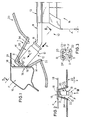
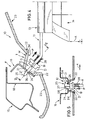
- a restraint 10 has a handrail 11 with an angled handrail end 12 and one with its upper or outer edge 13 on the Handrail 11 attached web 14 on.
- a sheet 16 is attached, from which a male-like Locking eye forming tongue 17 is bent out and at the same time the neighboring one Dachholm sheet metal part 18 in a recess, not shown interspersed.
- the locking eye 17 forms a window-like or otherwise undercut locking recess 19th
- the locking eye 17 thus points in the direction of the roller blind housing R.
- the handrail end 12 has a matrix shape Plug element a plug-in sleeve or plug-in sleeve 20 on. Within the plug-in sleeve 20 is known per se Way (cf. DE 30 08 298 C2) into its locking position spring-loaded latch part provided, which, in its locking position, the latch opening 19 reaches across.
- Bolt part is the handrail end 11 with an inside the push-in sleeve 20 sliding actuating part B provided.
- the circumferential outer edge 22 of the appropriate Plastic injection molded funnel T is based on the inner contour of the vehicle headlining 23 from.
- the inner surface IM of the insertion funnel T forms an insertion aid for the mounting of the Handrail end 12, such that the plug-in sleeve 20 involuntarily precisely guided over the locking eye 17 becomes.
- the exemplary embodiment corresponding to FIG. 4 and 5 differs from that according to FIGS. 1-3 by a modified form of the end of the support rod 12 and the vehicle mounting point F.
- the support rod 11 forms in the region of its end of the support rod 12 is a rectangular cross section, which is deformed into a hook 25.
- a bolt extension 27 passes through one of the hooks 25 exposed part of the locking opening 24.
- the hook 25 is in its locked position established.
- a sleeve-like actuating part B Connected in one piece to the bolt extension 27 is a sleeve-like actuating part B, which according to the arrow P together with the bar extension 27 against the restoring force of the handrail 11 enveloping helical compression spring 28 sliding can be to release the hook 25 from its locking position shown in FIGS. 4 and 5 bring about.
- the insertion of the handrail end 12 happens thereby as follows: after the end of the handrail 12 slid into the funnel T in the direction of insertion G. the sloping surface SR of the bolt extension 27 and the inclined surface SH of the hook 25 against the edge the locking opening 24.
- the helical compression spring 28 after, so that the remaining bolt extension 27 the hook 25 sliding along it initially space makes. So the hook 25, the latch opening 24 entirely penetrate, whereupon the spring 28 pressurized Sloping surface SR a radial displacement of the hook 25 causes the hook surface 26 in their locking position with the back of the hopper bottom 21 is moved.
- the vehicle travel direction is in FIGS. 2 and 5 indicated with x.
Landscapes
- Engineering & Computer Science (AREA)
- Mechanical Engineering (AREA)
- Transportation (AREA)
- Lock And Its Accessories (AREA)
- Connection Of Plates (AREA)
Description
Claims (11)
- Trenn- und/oder Rückhaltevorrichtung (10) für Fahrzeuge, wie für Kombinationskraftwagen od.dgl., mit einer von einer Aufnahme-Halterung (R), insbesondere etwa vertikal, ausziehbaren Werkstoffbahn (14), wie Netzbahn od.dgl., mit einer Haltestange (11), die zwei Haltestangenenden (12) aufweist, welche jeweils mit einer fahrzeugseitigen Befestigungsstelle (F) eine je ein matrizenförmiges und ein patrizenförmiges Steckelement aufweisende lösbare Steckverbindung bilden, gekennzeichnet durch folgende Merkmale:a) die fahrzeugseitige Befestigungsstelle (F) weist einen sich in Einführrichtung (G) des zugeordneten Haltestangenendes (12) verengenden Einführtrichter (T) auf;b) in der Trichterspitze oder auf dem Trichterboden (21) ist ein Steckelement (17; 24) angeordnet;c) mit dem Steckelement (17; 24) in der Trichterspitze oder auf dem Trichterboden (21) wirkt ein von dem zugehörigen Haltestangenende (12) gebildetes komplementäres Steckelement (20; 25) zusammen, welchem ein, insbesondere translatorisch, bewegliches Riegelelement (27) zugeordnet ist;d) das Riegelelement (27) ist mindestens mittelbar auf oder an dem Haltestangenende (12) geführt und in seine Verriegelungsstellung hinein federbelastet.
- Trenn- und/oder Rückhaltevorrichtung nach Anspruch 1, dadurch gekennzeichnet, daß dem Riegelement (27) haltestangenseitig eine Betätigungshandhabe (B) zugeordnet ist.
- Trenn- und/oder Rückhaltevorrichtung nach Anspruch 1 oder nach Anspruch 2, dadurch gekennzeichnet, daß das Steckelement (24; 20) matrizenförmig oder patrizenförmig und das komplementäre Steckelement (25; 17) patrizenförmig oder matrizenförmig ausgebildet ist.
- Trenn- und/oder Rückhaltevorrichtung nach einem der Ansprüche 1 bis 3, dadurch gekennzeichnet, daß aus dem Tiefsten des Einführtrichters (T) als patrizenförmiges Steckelement eine Stecköse (17) vorragt, mit welcher ein am Haltestangenende (12) angeordnetes matrizenartiges hülsen- oder muffenförmiges Bauteil (20) zusammenwirkt, welches ein in seine Verriegelungsstellung mit der Stecköse (17) hinein belastetes Riegelement enthält.
- Trenn- und/oder Rückhaltevorrichtung nach Anspruch 4, dadurch gekennzeichnet, daß die Stecköse (17) ein aus einem fahrzeugseitig befestigten Blechteil zungenartig herausgebogenes Ösenteil ist.
- Trenn- und/oder Rückhaltevorrichtung nach einem der Ansprüche 1 bis 3, dadurch gekennzeichnet, daß im Tiefsten des Einführtrichters (T) als matrizenartiges Steckelement eine sich etwa quer zur Achse des Einführtrichters (T) erstreckende, eine Rastöffnung (24) bildende Aussparung vorgesehen ist, welche in der Verriegelungsstellung der Steckverbindung von einem hakenförmig ausgebildeten Haltestangenende (25) hintergriffen ist.
- Trenn- und/oder Rückhaltevorrichtung nach Anspruch 6, dadurch gekennzeichnet, daß dem hakenförmig ausgebildeten Haltestangenende (25) ein Riegelement in Form eines Schieberiegels (27) zugeordnet ist.
- Trenn- und/oder Rückhaltevorrichtung nach Anspruch 7, dadurch gekennzeichnet, daß der Schieberiegel (27) an der einer Hakenfläche (26) abgewandten Mantelfläche der Haltestange (12) letztere innerhalb der Rastöffnung (24) hintergreift und so eine Aushakbewegung des Haltestangenendes (12) aus der Rastöffnung (24) lösbar blockiert.
- Trenn- und/oder Rückhaltevorrichtung nach Anspruch 7 oder nach Anspruch 8, dadurch gekennzeichnet, daß der Schieberiegel (27) in seine Verriegelungsstellung hinein federbelastet (28) ist.
- Trenn- und/oder Rückhaltevorrichtung nach Anspruch 8 oder nach Anspruch 9, dadurch gekennzeichnet, daß die Rastöffnung (24) von einem fahrzeugseitig befestigten Blech (16) gebildet ist, welches zugleich den Boden (21) bzw. das Tiefste des Einführtrichters (T) bildet.
- Trenn- und/oder Rückhaltevorrichtung nach einem der Ansprüche 1 bis 10, dadurch gekennzeichnet, daß der Einführtrichter (T) einen im wesentlichen geschlossen umlaufenden Trichtermantel (M) aufweist.
Applications Claiming Priority (4)
| Application Number | Priority Date | Filing Date | Title |
|---|---|---|---|
| DE19847583 | 1998-10-15 | ||
| DE19847583 | 1998-10-15 | ||
| DE19949417A DE19949417C2 (de) | 1998-10-15 | 1999-10-14 | Trenn- und/oder Rückhaltevorrichtung für Fahrzeuge, wie für Kombinationskraftwagen od. dgl. |
| DE19949417 | 1999-10-14 |
Publications (2)
| Publication Number | Publication Date |
|---|---|
| EP0997351A1 EP0997351A1 (de) | 2000-05-03 |
| EP0997351B1 true EP0997351B1 (de) | 2003-01-22 |
Family
ID=26049538
Family Applications (1)
| Application Number | Title | Priority Date | Filing Date |
|---|---|---|---|
| EP19990120420 Expired - Lifetime EP0997351B1 (de) | 1998-10-15 | 1999-10-14 | Trenn- und/oder Rückhaltevorrichtung für Fahrzeuge, wie für Kombinationskraftwagen od. dgl. |
Country Status (2)
| Country | Link |
|---|---|
| EP (1) | EP0997351B1 (de) |
| ES (1) | ES2189334T3 (de) |
Families Citing this family (1)
| Publication number | Priority date | Publication date | Assignee | Title |
|---|---|---|---|---|
| DE102022212293A1 (de) | 2022-11-18 | 2024-05-23 | Volkswagen Aktiengesellschaft | Raumtrenneinrichtung und Kraftfahrzeug |
Family Cites Families (5)
| Publication number | Priority date | Publication date | Assignee | Title |
|---|---|---|---|---|
| GB2224303A (en) * | 1988-10-28 | 1990-05-02 | Apex Load Control Co Ltd | Fastening load-carrying bars |
| DE3938776C1 (en) | 1989-11-23 | 1991-01-03 | Bayerische Motoren Werke Ag, 8000 Muenchen, De | Luggage space partition for camper vehicle - incorporates set of hooks with open funnel ends |
| SE466842B (sv) * | 1990-02-16 | 1992-04-13 | Volvo Ab | Inrullbart lastskyddsnaet |
| DE4010209C2 (de) | 1990-03-30 | 1994-03-10 | Baumeister & Ostler Gmbh Co | Sicherheitsnetz |
| DE4331278A1 (de) | 1993-09-15 | 1995-03-16 | Ieper Ind Nv | Rückhaltevorrichtung |
-
1999
- 1999-10-14 ES ES99120420T patent/ES2189334T3/es not_active Expired - Lifetime
- 1999-10-14 EP EP19990120420 patent/EP0997351B1/de not_active Expired - Lifetime
Also Published As
| Publication number | Publication date |
|---|---|
| EP0997351A1 (de) | 2000-05-03 |
| ES2189334T3 (es) | 2003-07-01 |
Similar Documents
| Publication | Publication Date | Title |
|---|---|---|
| EP0345438B1 (de) | Abdeckrollo oder - einrichtung für einen Kofferraum eines Kraftfahrzeuges | |
| DE10013531C1 (de) | Trenn- und Abdeckvorrichtung für Fahrzeuge, insbesondere für Kombinations-Personenkraftwagen od. dgl. | |
| DE19949417C2 (de) | Trenn- und/oder Rückhaltevorrichtung für Fahrzeuge, wie für Kombinationskraftwagen od. dgl. | |
| EP0754594A2 (de) | Abdeckeinrichtung mit hoher Crashsicherheit | |
| DE10261393B4 (de) | Höhenverstellbares Laderaumbodensystem | |
| DE102019115424A1 (de) | Dachschienen-airbag mit verdrehsicherung | |
| DE4221245C1 (de) | Sicherheitsgurtbefestigung an einem Haltebeschlag | |
| EP0385191B1 (de) | Laderaumabdeckvorrichtung für Kraftwagen, insbesondere für Kombinations-Personenkraftwagen | |
| DE19636316A1 (de) | Lösbar befestigter Heckaufsatz für ein Kraftfahrzeug | |
| EP0997351B1 (de) | Trenn- und/oder Rückhaltevorrichtung für Fahrzeuge, wie für Kombinationskraftwagen od. dgl. | |
| DE10205155B4 (de) | Kfz-Sicherheitseinrichtung, wie Laderaumabdeckung, Sicherheitsnetz oder dergleichen | |
| DE10205154B4 (de) | Kfz-Sicherheitseinrichtung, wie Laderaumabdeckung, Sicherheitsnetz, Sonnenrollo od.dgl. | |
| DE102009034584A1 (de) | Befestigungseinrichtung für einen Gurtbandumlenker | |
| EP1366942B1 (de) | Verdeckstoffbefestigung für ein Cabriolet | |
| DE102020113556B3 (de) | Bordwand eines Nutzfahrzeugs, Zurrelement und Zurranordnung | |
| EP1334876B1 (de) | Sicherheitsnetz zur Abtrennung eines Laderaums von einer Fahrgastzelle in einem Kraftfahrzeug | |
| EP3623219B1 (de) | Profil zur ladungssicherung sowie ladefläche zur aufnahme eines transportguts | |
| DE10341852B4 (de) | Aufrolleinrichtung, insbesondere ein Fangnetz- oder Abdeckrollo, zur Anordnung in einem Kraftfahrzeug | |
| DE4018860C2 (de) | ||
| DE102010035194A1 (de) | Vorrichtung zum Sichern von Ladung eines Fahrzeuges | |
| DE10046142B4 (de) | Vorrichtung zur Festlegung eines Endbereiches einer Fahrzeug- Sicherheitseinrichtung an einem fahrzeugseitigen Befestigungspunkt sowie zur Spannung des Endbereichs der Fahrzeug-Sicherheitseinrichtung relativ zu dem Befestigungspunkt | |
| DE102008039657B4 (de) | Befestigungselement zur Befestigung eines Bandes, insbesondere eines Fangbandes einer Airbaganordnung | |
| DE102004047234B4 (de) | Kraftfahrzeug und Gassack | |
| EP1356990B1 (de) | Kfz-Sicherheitseinrichtung, wie Laderaumabdeckung, Trennnetz od. dgl. | |
| DE2315909C3 (de) | Handkurbel, insbesondere Fensterkurbel für Fahrzeuge |
Legal Events
| Date | Code | Title | Description |
|---|---|---|---|
| PUAI | Public reference made under article 153(3) epc to a published international application that has entered the european phase |
Free format text: ORIGINAL CODE: 0009012 |
|
| AK | Designated contracting states |
Kind code of ref document: A1 Designated state(s): DE ES FR GB IT SE Kind code of ref document: A1 Designated state(s): DE ES FR GB IT |
|
| AX | Request for extension of the european patent |
Free format text: AL;LT;LV;MK;RO;SI |
|
| 17P | Request for examination filed |
Effective date: 20000520 |
|
| AKX | Designation fees paid |
Free format text: DE ES FR GB IT SE |
|
| GRAG | Despatch of communication of intention to grant |
Free format text: ORIGINAL CODE: EPIDOS AGRA |
|
| 17Q | First examination report despatched |
Effective date: 20020502 |
|
| GRAG | Despatch of communication of intention to grant |
Free format text: ORIGINAL CODE: EPIDOS AGRA |
|
| GRAH | Despatch of communication of intention to grant a patent |
Free format text: ORIGINAL CODE: EPIDOS IGRA |
|
| RBV | Designated contracting states (corrected) |
Designated state(s): DE ES FR GB IT |
|
| GRAH | Despatch of communication of intention to grant a patent |
Free format text: ORIGINAL CODE: EPIDOS IGRA |
|
| GRAA | (expected) grant |
Free format text: ORIGINAL CODE: 0009210 |
|
| AK | Designated contracting states |
Kind code of ref document: B1 Designated state(s): DE ES FR GB IT |
|
| REG | Reference to a national code |
Ref country code: GB Ref legal event code: FG4D Free format text: NOT ENGLISH |
|
| REF | Corresponds to: |
Ref document number: 59904082 Country of ref document: DE Date of ref document: 20030227 Kind code of ref document: P |
|
| GBT | Gb: translation of ep patent filed (gb section 77(6)(a)/1977) |
Effective date: 20030318 |
|
| REG | Reference to a national code |
Ref country code: ES Ref legal event code: FG2A Ref document number: 2189334 Country of ref document: ES Kind code of ref document: T3 |
|
| ET | Fr: translation filed | ||
| PLBE | No opposition filed within time limit |
Free format text: ORIGINAL CODE: 0009261 |
|
| STAA | Information on the status of an ep patent application or granted ep patent |
Free format text: STATUS: NO OPPOSITION FILED WITHIN TIME LIMIT |
|
| 26N | No opposition filed |
Effective date: 20031023 |
|
| PGFP | Annual fee paid to national office [announced via postgrant information from national office to epo] |
Ref country code: GB Payment date: 20051011 Year of fee payment: 7 |
|
| PG25 | Lapsed in a contracting state [announced via postgrant information from national office to epo] |
Ref country code: IT Free format text: LAPSE BECAUSE OF NON-PAYMENT OF DUE FEES Effective date: 20051014 |
|
| PGFP | Annual fee paid to national office [announced via postgrant information from national office to epo] |
Ref country code: ES Payment date: 20051014 Year of fee payment: 7 |
|
| PGFP | Annual fee paid to national office [announced via postgrant information from national office to epo] |
Ref country code: FR Payment date: 20051019 Year of fee payment: 7 |
|
| GBPC | Gb: european patent ceased through non-payment of renewal fee |
Effective date: 20061014 |
|
| REG | Reference to a national code |
Ref country code: FR Ref legal event code: ST Effective date: 20070629 |
|
| PG25 | Lapsed in a contracting state [announced via postgrant information from national office to epo] |
Ref country code: GB Free format text: LAPSE BECAUSE OF NON-PAYMENT OF DUE FEES Effective date: 20061014 |
|
| REG | Reference to a national code |
Ref country code: ES Ref legal event code: FD2A Effective date: 20061016 |
|
| PGFP | Annual fee paid to national office [announced via postgrant information from national office to epo] |
Ref country code: DE Payment date: 20071025 Year of fee payment: 9 |
|
| PG25 | Lapsed in a contracting state [announced via postgrant information from national office to epo] |
Ref country code: FR Free format text: LAPSE BECAUSE OF NON-PAYMENT OF DUE FEES Effective date: 20061031 Ref country code: ES Free format text: LAPSE BECAUSE OF NON-PAYMENT OF DUE FEES Effective date: 20061016 |
|
| PG25 | Lapsed in a contracting state [announced via postgrant information from national office to epo] |
Ref country code: DE Free format text: LAPSE BECAUSE OF NON-PAYMENT OF DUE FEES Effective date: 20090501 |