EP0997369A2 - Teleskopierbare Lenkspindel mit einem Deformationskörper - Google Patents
Teleskopierbare Lenkspindel mit einem Deformationskörper Download PDFInfo
- Publication number
- EP0997369A2 EP0997369A2 EP99120034A EP99120034A EP0997369A2 EP 0997369 A2 EP0997369 A2 EP 0997369A2 EP 99120034 A EP99120034 A EP 99120034A EP 99120034 A EP99120034 A EP 99120034A EP 0997369 A2 EP0997369 A2 EP 0997369A2
- Authority
- EP
- European Patent Office
- Prior art keywords
- shear
- steering spindle
- spindle according
- shear body
- section
- Prior art date
- Legal status (The legal status is an assumption and is not a legal conclusion. Google has not performed a legal analysis and makes no representation as to the accuracy of the status listed.)
- Withdrawn
Links
Images


Classifications
-
- B—PERFORMING OPERATIONS; TRANSPORTING
- B62—LAND VEHICLES FOR TRAVELLING OTHERWISE THAN ON RAILS
- B62D—MOTOR VEHICLES; TRAILERS
- B62D1/00—Steering controls, i.e. means for initiating a change of direction of the vehicle
- B62D1/02—Steering controls, i.e. means for initiating a change of direction of the vehicle vehicle-mounted
- B62D1/16—Steering columns
- B62D1/18—Steering columns yieldable or adjustable, e.g. tiltable
- B62D1/19—Steering columns yieldable or adjustable, e.g. tiltable incorporating energy-absorbing arrangements, e.g. by being yieldable or collapsible
- B62D1/192—Yieldable or collapsible columns
-
- F—MECHANICAL ENGINEERING; LIGHTING; HEATING; WEAPONS; BLASTING
- F16—ENGINEERING ELEMENTS AND UNITS; GENERAL MEASURES FOR PRODUCING AND MAINTAINING EFFECTIVE FUNCTIONING OF MACHINES OR INSTALLATIONS; THERMAL INSULATION IN GENERAL
- F16B—DEVICES FOR FASTENING OR SECURING CONSTRUCTIONAL ELEMENTS OR MACHINE PARTS TOGETHER, e.g. NAILS, BOLTS, CIRCLIPS, CLAMPS, CLIPS OR WEDGES; JOINTS OR JOINTING
- F16B2200/00—Constructional details of connections not covered for in other groups of this subclass
- F16B2200/63—Frangible connections
Definitions
- the invention relates to a telescopic steering spindle, especially for a motor vehicle, with an external Jacket tube and with a nozzle, the jacket tube and the nozzle connected by means of a deformation body are.
- the deformation body prevents a retroactive effect of the on Deformation forces acting on the vehicle on the driver. In particular, there is an axial displacement the steering spindle in the passenger compartment prevented. At In some embodiments, the deformation body also used to in the event of a driver impact the risk of injury to the steering wheel is as low as possible hold.
- the deformation body is for example with a Break or break point provided that the telescopic Push the connector into the outer jacket tube allows once a predetermined maximum Force is exceeded.
- the deformation element is for this a known configuration designed as a tear-off tab, the nozzle in the event of excessive force is torn open to the outside.
- the invention is based on the problem of a steering spindle of the type mentioned at the beginning so that this is a reliable transmission in normal driving the steering forces possible and at the same time above one freely adjustable value a transfer of external Forces on the driver prevented. At the same time Manufacturing tolerances no or only insignificant Have an impact on operational safety and the Assembly process as well as the adaptation to different application purposes be relieved.
- the deformation body has a shear body which a shear area deviating from its cross-sectional area having.
- the shear body can in particular dimensions have a simple and in the assembly process Enable error-free connection. This allows for example, manufacturing processes used that have comparatively high tolerance values or a special shape of the shaving body require. The adjustment of the desired shear forces allows universal use of the shaving body with different vehicles.
- a particularly advantageous development of the invention is given by the fact that the shear body is built into its Position in the area between the casing tube and the nozzle one compared to the remaining cross-sectional area has reduced shear area.
- a particularly favorable development of the invention is also given when the shaving body two together has positively connected sections which by means of of a shear pin determining the shear surface are.
- the shear pin can be of any dimension, have different material properties and detachable or permanently connected to the two sections his. This is also a particularly useful connection given that the shear pin has an interference fit. This allows the two sections of the shaving body are first put together to form a structural unit, so the subsequent manufacturing process is essential is facilitated. At the same time, a precise and reliable determination of the shear force and prevent incorrect installation.
- a particularly simple embodiment of the invention is also given that the shear body one with a Has projection provided first portion, which in a corresponding recess of a second section is inserted.
- This allows the assembly process can be further simplified by making the shear body out there are only two parts. It can be different Refinements to facilitate assembly are provided be, for example, the outer dimensions even with different shear surfaces are.
- the invention is particularly simple in that that the shaving body one after inserting the shaving body has removable core in the steering shaft.
- the shaving body can do this during the assembly process in particular be designed as a solid molded part, which thereby a trouble-free production and transmission high assembly forces.
- the cross-sectional area is the desired one Shear area reduced.
- Embodiments in which the Core of the shaving body by any, for example machining, removed, are also conceivable like the use of one with different material properties equipped core.
- the core can too executed as part of a tool and thereby only into the shaving body during the assembly process be used.
- a particularly effective modification of the invention is also given that the shear body at least one reducing the cross-sectional area to the size of the shear area Has recess. Such a recess is easy to install, allowing quick adjustment to the permissible shear forces.
- shear body a substantially circular cross-sectional area having. This largely eliminates assembly errors become. At the same time, notch effects can result from Edges on the shaving body and the associated effects to the permissible shear stress can be prevented.
- a particularly suitable embodiment of the invention is also given by the fact that the steering spindle has several distributed approximately evenly over the circumference Has shear body. Possible influences due to bending moments this can largely affect the shear body be prevented. Several of the Shear body can be combined into one structural unit or one shear body several, distributed over the circumference Have shear areas.
- shear body is made of steel is made.
- the material properties of such executed shear body are therefore also at high loads customizable.
- the shear body is opposite Insensitive to temperature fluctuations and corrosion.
- the outer casing tube and the socket can be form-fitting be inserted into each other so that a relative Rotational movement to each other is limited to a small extent or is completely excluded. Particularly advantageous it is, however, if the outer casing tube and the nozzle only rotatably connected by means of the shaving body are. This will in the event of excessive force on the steering shaft a transmission axial and radial Forces prevented. The driver's passive safety is significantly increased.
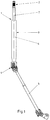
- Figure 1 shows a perspective view two-piece steering shaft 1 of a motor vehicle, the a steering wheel holder 2 provided upper part 3 by means of a universal joint 4 connected to a lower part 5 is.
- the upper part 3 of the steering spindle 1 has a tubular casing 6, in which a nozzle 7 telescopically in the event of a crash can be inserted.
- One from the outside on the steering spindle 1 acting force that exceeds the permissible value therefore not on the steering wheel mount 2 and thus on the Driver of one equipped with the steering spindle 1 Transfer vehicle, but causes the insertion of the connector 7 in the casing tube 6.
- FIG. 2 shows a cut along its longitudinal axis and shortened representation of the upper part 3 of the steering spindle 1.
- Each a guide 8, 9 determines the distance between the casing tube 6 and the nozzle 7, so that jamming of the Nozzle 7 in the jacket tube 6 even with a bending load can be excluded.
- In the operating state shown prevents both through the wall of the Jacket tube 6 as well as through the nozzle 7 Shear body 10 whose unintentional relative movement.
- a cross section through the casing tube 6 and the nozzle 7 shows FIG. 3.
- the shear body 10 is such in the Steering spindle 1 used that the first section 11 of the Shear body 10 protrudes through the casing tube 6 and the second section 12 of the shaving body 10 in the likewise protrudes as a hollow body 7. Shearing the shaving body 10 enables both an axial displacement as well as a rotational mobility of the casing tube 6 and the nozzle 7 against each other. To assemble the shaving body 10, this can be done by its high axial load capacity directly through the Wall of the nozzle 7 and the jacket tube 6 driven through without a corresponding recess must be provided in nozzle 7 and / or jacket tube 6.
- Figure 4 shows the shear body 10 in an enlarged and partially sectioned side view.
- the two-part design of the shaving body 10 wherein the second section 12 has a projection 13 which by means of a press fit into a corresponding one Recess 14 of the first section 11 is inserted.
- a acting transversely to the longitudinal axis of the shaving body 10 Shear stress is therefore only on the ledge 13 transferred.
- the cross-sectional area of the protrusion 13 can easily be adapted to different applications become.
- the design of the lead influences 13 the axial load capacity of the shaving body 10 only insignificant.
- the outer dimensions of the shaving body 10 can therefore, for example, on the desired Manufacturing processes or design requirements optimal be matched and in particular also designed in this way be that the shear body 10 with great force driven through the nozzle 7 and the jacket tube 6 can be.
- a modified embodiment of a Shaving body 15 shows Figure 5 in a partially sectioned Side view.
- the shaving body has 15 a core 16, which in the illustrated, initially still not inserted in a steering spindle, gap-free inserted over the full length of the shaving body 15 in this is.
- the core 16 can be removed from the shear body 15, so that the shear area is only through the remaining Edge region of the shear body 15 is formed.
- the core 16 can also be a first section connected in one piece to the shear body 15 be, for example, after insertion in a steering spindle by drilling or other machining processes Will get removed.
- FIG 6 is a two-part embodiment of a Shear body 17 shown, the two sections 18 and 19th by means of a shear pin determining the shear area 20 are connected.
- the two sections 18, 19 each have a recess 21, 22 into which the shear pin 20 is used with a press fit.
- a suitable shear pin 20 with the desired material properties the maximum permissible shear stress determine.
- the shear pin 20 can, for example also be screwed into the recesses 18, 19.
- FIG 7. A simple embodiment of a shear body 23 is shown in FIG 7.
- the one-piece shear body 23 has a plurality of Recesses 24 designed as bores which thus for a transverse to the longitudinal axis of the shear body 23 attacking force form a predetermined breaking point, the permissible shear stress determining shear area by the remaining cross-sectional area is determined.
- This is in an assembled state, a first section 25 in a jacket tube, not shown, and a second section 26 used in a nozzle, not shown.
- the recesses 24 can thereby easily be adapted to the respective purpose.
Landscapes
- Engineering & Computer Science (AREA)
- Chemical & Material Sciences (AREA)
- Combustion & Propulsion (AREA)
- Transportation (AREA)
- Mechanical Engineering (AREA)
- Steering Controls (AREA)
- Vibration Dampers (AREA)
Abstract
Description
- Fig. 1
- eine perspektivische Ansicht einer Lenkspindel,
- Fig. 2
- einen Längsschnitt durch einen oberen Teilbereich der Lenkspindel mit einem Mantelrohr und einem Stutzen,
- Fig. 3
- einen Querschnitt durch das Mantelrohr und den Stutzen,
- Fig. 4
- einen Scherkörper der Lenkspindel in einer teilweise geschnittenen Seitenansicht,
- Fig. 5
- eine andere Ausführung eines erfindungsgemäßen Scherkörpers in einer teilweise geschnittenen Seitenansicht,
- Fig. 6
- eine weitere Ausführung eines zweiteiligen Scherkörpers mit einem Scherstift in einer teilweise geschnittenen Seitenansicht,
- Fig. 7
- eine einteilige Ausführungsform eines Scherkörpers in einer Seitenansicht.
Claims (11)
- Teleskopierbare Lenkspindel, insbesondere für ein Kraftfahrzeug, mit einem äußeren Mantelrohr und mit einem Stutzen, wobei das Mantelrohr und der Stutzen mittels eines Deformationskörpers verbunden sind, dadurch gekennzeichnet, dass der Deformationskörper einen Scherkörper (10, 15, 17, 23) aufweist, der eine von seiner Querschnittsfläche abweichende Scherfläche aufweist.
- Lenkspindel nach Anspruch 1, dadurch gekennzeichnet, dass der Scherkörper (10, 15, 17, 23) in seiner eingebauten Position im Bereich zwischen dem Mantelrohr (6) und dem Stutzen (7) eine gegenüber der übrigen Querschnittsfläche verkleinerte Scherfläche aufweist.
- Lenkspindel nach Anspruch 1 oder 2, dadurch gekennzeichnet, dass der Scherkörper (17) zwei miteinander formschlüssig verbundene Abschnitte (18, 19) aufweist, die mittels eines die Scherfläche bestimmenden Scherstiftes (20) verbunden sind.
- Lenkspindel nach einem der vorhergehenden Ansprüche, dadurch gekennzeichnet, dass der Scherstift (20) eine Presspassung aufweist.
- Lenkspindel nach einem der vorhergehenden Ansprüche, dadurch gekennzeichnet, dass der Scherkörper (10) einen mit einem Vorsprung (13) versehenen ersten Abschnitt (12) aufweist, welcher in eine entsprechende Ausnehmung (14) eines zweiten Abschnitts (11) eingesetzt ist.
- Lenkspindel nach einem der vorhergehenden Ansprüche, dadurch gekennzeichnet, dass der Scherkörper (15) einen nach dem Einsetzen des Scherkörpers (15) in die Lenkspindel (1) entfernbaren Kern (16) aufweist.
- Lenkspindel nach einem der vorhergehenden Ansprüche, dadurch gekennzeichnet, dass der Scherkörper (23) zumindest eine die Querschnittsfläche auf das Maß der Scherfläche verringernde Ausnehmung (24) aufweist.
- Lenkspindel nach einem der vorhergehenden Ansprüche, dadurch gekennzeichnet, dass der Scherkörper (10, 15, 17, 23) eine im wesentlichen kreisförmige Querschnittsfläche aufweist.
- Lenkspindel nach einem der vorhergehenden Ansprüche, dadurch gekennzeichnet, dass die Lenkspindel (1) mehrere, über den Umfang in etwa gleichmäßig verteilte Scherkörper (10, 15, 17, 23) aufweist.
- Lenkspindel nach einem der vorhergehenden Ansprüche, dadurch gekennzeichnet, dass der Scherkörper (10, 15, 17, 23) aus Stahl hergestellt ist.
- Lenkspindel nach einem der vorhergehenden Ansprüche, dadurch gekennzeichnet, dass das äußere Mantelrohr (6) und der Stutzen (7) lediglich mittels des Scherkörpers (10, 15, 17, 23) drehfest verbunden sind.
Applications Claiming Priority (2)
| Application Number | Priority Date | Filing Date | Title |
|---|---|---|---|
| DE19849262A DE19849262A1 (de) | 1998-10-26 | 1998-10-26 | Teleskopierbare Lenkspindel mit einem Deformationskörper |
| DE19849262 | 1998-10-26 |
Publications (2)
| Publication Number | Publication Date |
|---|---|
| EP0997369A2 true EP0997369A2 (de) | 2000-05-03 |
| EP0997369A3 EP0997369A3 (de) | 2002-08-07 |
Family
ID=7885641
Family Applications (1)
| Application Number | Title | Priority Date | Filing Date |
|---|---|---|---|
| EP99120034A Withdrawn EP0997369A3 (de) | 1998-10-26 | 1999-10-18 | Teleskopierbare Lenkspindel mit einem Deformationskörper |
Country Status (4)
| Country | Link |
|---|---|
| US (1) | US6339970B1 (de) |
| EP (1) | EP0997369A3 (de) |
| BR (1) | BR9904937A (de) |
| DE (1) | DE19849262A1 (de) |
Cited By (1)
| Publication number | Priority date | Publication date | Assignee | Title |
|---|---|---|---|---|
| DE102007060149A1 (de) | 2007-12-13 | 2009-06-18 | GM Global Technology Operations, Inc., Detroit | Teleskopierbare Lenkspindelanordnung |
Families Citing this family (20)
| Publication number | Priority date | Publication date | Assignee | Title |
|---|---|---|---|---|
| DE10053987A1 (de) * | 2000-10-31 | 2002-05-08 | Ina Schaeffler Kg | Längenverstellbare Welle |
| US6729648B2 (en) | 2002-06-07 | 2004-05-04 | Sealy Technology Llc | Non-linear energy absorbing column assembly |
| US7048306B2 (en) * | 2002-09-05 | 2006-05-23 | Delphi Technologies, Inc. | Steering column with tubular structure |
| DE102004024876B4 (de) * | 2003-09-10 | 2009-04-09 | Daimler Ag | Lenksäulenanordnung mit einer in ihrer Neigung und Länge veränderbaren Lenksäule |
| JP2005090450A (ja) | 2003-09-19 | 2005-04-07 | Hino Motors Ltd | 排気浄化装置 |
| US7784830B2 (en) * | 2003-10-23 | 2010-08-31 | Chrysler Group Llc | Axially adjustable steering column assembly with flexible bearing sleeve |
| US20050137020A1 (en) * | 2003-12-17 | 2005-06-23 | Beechie Brian E. | Controlled collapsible drive line arrangement |
| US7798583B2 (en) * | 2005-06-10 | 2010-09-21 | Central Industrial Supply Company | Detent pin bearing retainer lock for a drawer slide |
| US20100156081A1 (en) * | 2005-10-06 | 2010-06-24 | Hyundai Motor Company | Impact absorbing device for steering column of vehicle |
| US7661711B2 (en) * | 2006-10-26 | 2010-02-16 | Gm Global Technology Operations, Inc. | Steering column assembly with active energy absorption device |
| US7800150B2 (en) * | 2007-05-29 | 2010-09-21 | United Microelectronics Corp. | Semiconductor device |
| US7905518B2 (en) * | 2007-07-19 | 2011-03-15 | Fci Americas Technology, Inc. | Collapsible vehicle steering column |
| DE102008005256B4 (de) * | 2008-01-18 | 2009-10-22 | Thyssenkrupp Presta Ag | Lenksäule mit Kunststoffgleithülse |
| US8627742B2 (en) * | 2008-04-04 | 2014-01-14 | Steering Solutions Ip Holding Corporation | Steering column assembly with shearable jacket connector |
| WO2015064393A1 (ja) * | 2013-10-30 | 2015-05-07 | 日本精工株式会社 | ステアリング装置 |
| WO2015064392A1 (ja) * | 2013-10-30 | 2015-05-07 | 日本精工株式会社 | ステアリング装置 |
| JP6192108B2 (ja) * | 2013-12-26 | 2017-09-06 | 株式会社ジェイテクト | ピン組立体およびステアリング装置 |
| WO2016035515A1 (ja) * | 2014-09-02 | 2016-03-10 | 日本精工株式会社 | ステアリング装置 |
| JP2017124715A (ja) * | 2016-01-13 | 2017-07-20 | 株式会社ショーワ | 操舵装置 |
| US12092138B2 (en) | 2022-04-08 | 2024-09-17 | Toyota Motor Engineering & Manufacturing North America, Inc. | Coupling assemblies having frangible portions |
Family Cites Families (6)
| Publication number | Priority date | Publication date | Assignee | Title |
|---|---|---|---|---|
| US3864988A (en) * | 1973-05-14 | 1975-02-11 | Chrysler Corp | Energy absorbing steering column |
| US4117741A (en) * | 1976-12-01 | 1978-10-03 | Honda Giken Kogyo Kabushiki Kaisha | Collapsible steering column |
| FR2374554A1 (fr) * | 1976-12-20 | 1978-07-13 | Nadella | Transmission collapsable |
| CA1131946A (en) * | 1977-09-07 | 1982-09-21 | Donald L. Smith | Shear pin release system |
| US4177352A (en) * | 1978-05-25 | 1979-12-04 | Interpace Corporation | Shear bolt assembly for a load limiting line support for a post insulator |
| US5567096A (en) * | 1994-09-13 | 1996-10-22 | Howard; Douglas D. | Shear-pin system for logging truck bunk |
-
1998
- 1998-10-26 DE DE19849262A patent/DE19849262A1/de not_active Withdrawn
-
1999
- 1999-10-18 EP EP99120034A patent/EP0997369A3/de not_active Withdrawn
- 1999-10-21 US US09/425,843 patent/US6339970B1/en not_active Expired - Fee Related
- 1999-10-26 BR BR9904937-6A patent/BR9904937A/pt active Search and Examination
Non-Patent Citations (1)
| Title |
|---|
| None |
Cited By (2)
| Publication number | Priority date | Publication date | Assignee | Title |
|---|---|---|---|---|
| DE102007060149A1 (de) | 2007-12-13 | 2009-06-18 | GM Global Technology Operations, Inc., Detroit | Teleskopierbare Lenkspindelanordnung |
| US7975569B2 (en) | 2007-12-13 | 2011-07-12 | GM Global Technology Operations LLC | Telescopable steering spindle arrangement |
Also Published As
| Publication number | Publication date |
|---|---|
| DE19849262A1 (de) | 2000-04-27 |
| EP0997369A3 (de) | 2002-08-07 |
| US6339970B1 (en) | 2002-01-22 |
| BR9904937A (pt) | 2000-08-15 |
Similar Documents
| Publication | Publication Date | Title |
|---|---|---|
| EP0997369A2 (de) | Teleskopierbare Lenkspindel mit einem Deformationskörper | |
| DE3943535C2 (de) | Verbindungsanordnung | |
| DE19526769C2 (de) | Verfahren zur Herstellung einer stoßabsorbierenden Lenkwelle | |
| EP2445772B1 (de) | Lenkwellenbauteil, lenkwelle und herstellungsverfahren | |
| EP1869334B1 (de) | Gleitlager, gleitlagersystem und montage eines gleitlagersystems | |
| DE8120936U1 (de) | Rohrfensterheber, insbesondere fuer kraftfahrzeugfenster | |
| EP0661474A1 (de) | Wellen-Befestigung | |
| DE102006048678B4 (de) | Kupplungsvorrichtung | |
| DE2321915A1 (de) | Zusammenschiebbare lenksaeulenanordnung | |
| DE102012022876A1 (de) | Verstärkungselement zur Verstärkung eines Hohlprofils sowie Hohlprofil mit einem solchen Verstärkungselement | |
| EP1642037B1 (de) | Lageranordnung für ein kraftfahrzeug | |
| DE3920793C2 (de) | Verbindungsanordnung | |
| EP1294594B1 (de) | Überlastsicherung und ein verfahren zu deren herstellung | |
| WO1999058864A9 (de) | Befestigungssystem mit einer kunststoffummantelten schraube | |
| DE10060229B4 (de) | Verschiebeanordnung für eine Gelenkwelle | |
| DE3347503A1 (de) | Selbstsichernder sperrbolzen | |
| EP3524836B1 (de) | Axialkugelzapfen | |
| DE102009046141A1 (de) | Lenkgetriebe für ein Lenksystem und Verfahren zur Montage desselben | |
| DE10291501T5 (de) | Lager für ein mechanisches Wälzübertragungselement | |
| DE10248372B4 (de) | Gegenbahngelenk | |
| EP0458126A2 (de) | Selbstsichernder Sperrbolzen | |
| DE10143805B4 (de) | Bolzenführungseinheit für eine Schwimmsattel-Scheibenbremse | |
| DE19910308A1 (de) | Gummilager mit Axialanschlägen und Verfahren zur Herstellung eines Gummilagers mit integrierten Axialanschlägen | |
| EP1419078A1 (de) | Gegen crash gesicherter unterdruckbremskraftverstärker für kraftfahrzeuge | |
| EP1439978B1 (de) | Getriebe-antriebseinheit mit einem adapter |
Legal Events
| Date | Code | Title | Description |
|---|---|---|---|
| PUAI | Public reference made under article 153(3) epc to a published international application that has entered the european phase |
Free format text: ORIGINAL CODE: 0009012 |
|
| AK | Designated contracting states |
Kind code of ref document: A2 Designated state(s): AT BE CH CY DE DK ES FI FR GB GR IE IT LI LU MC NL PT SE |
|
| AX | Request for extension of the european patent |
Free format text: AL;LT;LV;MK;RO;SI |
|
| RAP1 | Party data changed (applicant data changed or rights of an application transferred) |
Owner name: SIEMENS AKTIENGESELLSCHAFT |
|
| PUAL | Search report despatched |
Free format text: ORIGINAL CODE: 0009013 |
|
| AK | Designated contracting states |
Kind code of ref document: A3 Designated state(s): AT BE CH CY DE DK ES FI FR GB GR IE IT LI LU MC NL PT SE |
|
| AX | Request for extension of the european patent |
Free format text: AL;LT;LV;MK;RO;SI |
|
| 17P | Request for examination filed |
Effective date: 20020905 |
|
| AKX | Designation fees paid |
Designated state(s): DE ES FR GB |
|
| 17Q | First examination report despatched |
Effective date: 20030603 |
|
| STAA | Information on the status of an ep patent application or granted ep patent |
Free format text: STATUS: THE APPLICATION IS DEEMED TO BE WITHDRAWN |
|
| 18D | Application deemed to be withdrawn |
Effective date: 20050315 |