EP0997401A2 - Verfahren und Vorrichtung zur Handhabung von stückigem Gut, insbesondere von Arzneimitteln - Google Patents
Verfahren und Vorrichtung zur Handhabung von stückigem Gut, insbesondere von Arzneimitteln Download PDFInfo
- Publication number
- EP0997401A2 EP0997401A2 EP99118904A EP99118904A EP0997401A2 EP 0997401 A2 EP0997401 A2 EP 0997401A2 EP 99118904 A EP99118904 A EP 99118904A EP 99118904 A EP99118904 A EP 99118904A EP 0997401 A2 EP0997401 A2 EP 0997401A2
- Authority
- EP
- European Patent Office
- Prior art keywords
- shelf
- goods
- manipulator
- receptacle
- trough
- Prior art date
- Legal status (The legal status is an assumption and is not a legal conclusion. Google has not performed a legal analysis and makes no representation as to the accuracy of the status listed.)
- Granted
Links
- 238000000034 method Methods 0.000 title claims abstract description 21
- 239000003814 drug Substances 0.000 title description 7
- 239000000463 material Substances 0.000 title description 6
- 238000012946 outsourcing Methods 0.000 claims 2
- 230000002093 peripheral effect Effects 0.000 claims 1
- 229940126601 medicinal product Drugs 0.000 abstract 1
- 238000013461 design Methods 0.000 description 3
- 238000011161 development Methods 0.000 description 3
- 229940079593 drug Drugs 0.000 description 3
- 239000011521 glass Substances 0.000 description 3
- 238000004806 packaging method and process Methods 0.000 description 3
- 206010000496 acne Diseases 0.000 description 2
- 230000001133 acceleration Effects 0.000 description 1
- 238000013459 approach Methods 0.000 description 1
- 230000003749 cleanliness Effects 0.000 description 1
- 238000010276 construction Methods 0.000 description 1
- 230000003993 interaction Effects 0.000 description 1
- 238000004519 manufacturing process Methods 0.000 description 1
- 239000010816 packaging waste Substances 0.000 description 1
- 238000005192 partition Methods 0.000 description 1
- 230000008092 positive effect Effects 0.000 description 1
- 230000000717 retained effect Effects 0.000 description 1
- 239000013589 supplement Substances 0.000 description 1
- 238000012549 training Methods 0.000 description 1
Images


Classifications
-
- B—PERFORMING OPERATIONS; TRANSPORTING
- B65—CONVEYING; PACKING; STORING; HANDLING THIN OR FILAMENTARY MATERIAL
- B65G—TRANSPORT OR STORAGE DEVICES, e.g. CONVEYORS FOR LOADING OR TIPPING, SHOP CONVEYOR SYSTEMS OR PNEUMATIC TUBE CONVEYORS
- B65G1/00—Storing articles, individually or in orderly arrangement, in warehouses or magazines
- B65G1/02—Storage devices
- B65G1/04—Storage devices mechanical
- B65G1/0407—Storage devices mechanical using stacker cranes
-
- B—PERFORMING OPERATIONS; TRANSPORTING
- B65—CONVEYING; PACKING; STORING; HANDLING THIN OR FILAMENTARY MATERIAL
- B65G—TRANSPORT OR STORAGE DEVICES, e.g. CONVEYORS FOR LOADING OR TIPPING, SHOP CONVEYOR SYSTEMS OR PNEUMATIC TUBE CONVEYORS
- B65G1/00—Storing articles, individually or in orderly arrangement, in warehouses or magazines
- B65G1/02—Storage devices
- B65G1/04—Storage devices mechanical
- B65G1/045—Storage devices mechanical in a circular arrangement, e.g. towers
Definitions
- the invention relates to a method and a device for handling lumpy, in particular small good, especially from in containers such as e.g. Cans, bottles or the like Medicines that are also in boxes can be packed according to the generic terms of Claims 1 and 11.
- the invention is preferred in Pharmacies, drug stores and the like deployed.
- Such devices are known from practice. These facilities are in parallel to a shelf wall on the floor and on the ceiling one guide rail each. In these guide rails drives a manipulator.
- the manipulator has a guidance system in the lower and in the upper Guide rail. Between the two management systems there is an essentially vertical one Guide pillar. On this pillar is a - perpendicular to the shelf wall - movable goods holder appropriate.
- the manipulator is state of the art computer controlled.
- the shelf wall is the manipulator open towards.
- the lumpy good lies on levels - often glassy - in the pharmaceutical sector.
- the distances of the piece goods on the shelf, parallel to the shelf front for example formed by partitions or by precise alignment of the piece goods when loading on the shelf achieved.
- the good pick-up is, for example, horizontal acting gripper.
- Another construction The good intake is structured as follows: A movable suction device acts on the front of the good. Include two circumferential bands the estate left and right. By interaction of the Suction device and the belts the goods on a plate in front of the shelf Good admission promoted.
- the goods are the manipulator on a storage space or stored further transport system.
- a shelf that is provided in a new way with recesses in the form of aisles or with openings in the form of slots that are open at least to the front of the shelf, usually the front, and that also has a non-flat top / support surface , on the one hand, nevertheless fulfills the requirements of the pharmaceutical sector and, in combination with the new design of the manipulator, also enables a faster approach of the good intake to the good to be removed.
- the new design of the shelf in particular its support surface for the lumpy good, and the new good receptacle, which is equipped with "fingers" corresponding to the recesses, make the manipulator and its parts coarser to the position of the good Tolerances when positioning than previously possible; this advantage has a particularly positive effect on the total transport time for the goods from the shelf compartment to a predefinable position within the intended transport route.
- the good is safe thanks to the inventive solution and quickly lifted out of the shelf; the withdrawal with a suction or clamping device, those with the dangers described earlier and imponderables is eliminated.
- a flat shelf surface is not absolutely necessary.
- Positioning troughs for the goods in the shelf have the advantage that the goods have a defined shelf position that can be stored and called up.
- the preferably and essentially V-shaped position trough has a self-centering function for the goods, so the goods (the goods) no longer need to be placed extremely precisely when the shelves are fitted.
- This advantage has a further advantage:
- the loading can now also be carried out by a manipulator, preferably the manipulator, who takes the goods from the shelf.
- a manipulator preferably the manipulator
- a simple magazine which is constantly exchanged, for example when transporting between wholesalers and pharmacists, a further time and cost advantage is achieved.
- the goods can no longer slip, it is also possible to accommodate them in a cylinder jacket surface that is open to the outside and has compartments, for example in a so-called column shelf.
- the manipulator only needs to be moved perpendicularly and radially to the cylinder surface. While on a shelf with a level removal front all the movements have to be done by the manipulator alone, the cylinders and the manipulator "share" the paths in this embodiment according to the invention. Any forces on the goods due to acceleration or deceleration forces due to the cylinder rotation do not cause the goods to slip in the shelf compartment because of the preferably V-shaped shape of the trough.
- the manipulator is relatively short horizontal Paths, for example parallel along several Cylinder surface, can cover.
- the manipulator according to the invention can therefore also Operate cylinders and / or flat shelf walls.
- the individual shelf troughs can according to the new Solution may be of different sizes, with one in particular integer enlargement factor. This applies especially to diamond-shaped shelves, that by crossing, sloping Shelves are formed.
- the depressions or alleys can be one diamond-shaped cross-section or a wavy or have a zigzag cross-section.
- Figure 1 is a cross section through the slotted Good shot 1 and the slotted shelf recess 2 an embodiment variant of the new device shown. Both parts essentially have one V-shaped cross section.
- goods 5 e.g. a round bottle or a rectangular box
- the good 5 is now shifted from the fingers 11 of the Shelf trough 2 on the fingers 10 of the good holder 1. So that the good 5 does not come out of the shelf recess 2 or the well receptacle 1 can slip out both preferably on their front outer edges Stops 9a and 9.
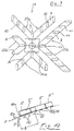
- Figure 2 illustrates through its top view how the fingers 10 of the good receptacle 1 through Slots 8 formed breakthroughs of the shelf trough 2 comb through.
- the V-shaped contact surface of the goods receptacle 1 is realized by knobs 12 of different lengths, which are arranged on a common plate 1a.
- the free ends of the knobs 12 form support points 19 which are profiled for reasons of better adhesion of the material 5, in particular beveled in the sense of the V-shape.
- the knobs 12, which are also preferably made of a rubber-like material, prevent the material 5 from slipping during removal. In the shelf trough 2, said stop 9a secures the goods.
- the knobs 12, analogously to the fingers 10 are passed through the openings formed by slots 8 in the shelf recess 2 between their fingers 11.
- FIG. 3 shows 4 shows the row-shaped, with the slots 8th corresponding arrangement of the knobs 12 on the Plate 1a of the well receptacle 1.
- shelf troughs 2 are shaped in such a way that a plurality of goods - with respect to the front of the shelf surface - are arranged next to one another, see FIG. 12.
- the other now steeper leg of the V-shaped shelf trough has been shortened to such an extent that it is only a stop 18a at the lowest point of the bearing surface 18 formed by the other leg.
- the long leg forming the support surface 18 of the now more L-shaped shelf trough is also provided with openings in the form of slots 18 and the associated good receptacle 1 here also has fingers 10 and is adapted to the special L-shape.
- the deepest finger 10 of this good receptacle 1 is laterally provided with a short stop 10a with which the good 5, 5 ', 5''is prevented from sliding down.
- the width "B" of the goods receptacle 1, ie the number of fingers 10, is selected here so that the goods receptacle 1 can hold goods 5, 5 ', 5''of different widths.
- the good pick-up can additionally be displaced in the positioning direction "P", so that only the required number of fingers 10 of the good pick-up 1 the respective good 5, 5 'or 5''to be removed reach under.
- the good receptacle 1 and the good 5 ' were again drawn in dashed lines in FIG. After removal of the front goods 5, here the goods 5 ', 5''then slide forward to the stop 18a of the support surface 18.
- the widths of the slots 8 and the fingers 10 are coordinated here in such a way that the goods receptacle 1 can carry out an essentially vertically directed lifting movement H for removing the goods 5, 5 ', 5''.
- the good receptacle 1 is additionally pivotally mounted on the manipulator 3 in several axes.
- the inclined shelf troughs 2 which rise to the rear, reach into the depth, so that several goods are arranged one behind the other.
- the slots 8 are rotated here by 90 ° relative to the illustration in FIG. 12, that is to say directed from the front to the rear, in the shelf recess 2.
- the front section which accommodates a piece 5, of the shelf recess 2, which is longer and inclined compared to the basic variant, is at least approximately angled into the horizontal.
- the manipulator 3 in particular the goods receptacle 1, is positioned horizontally relative to the goods lying at the lowest point of the shelf trough 2 such that the free ends of the fingers 10 of the goods receptacle 1 in the direction of the shelf depth do not project beyond the rear end of the goods to be picked up.
- the good receptacle 1 is preferably pivotable about at least one axis.
- FIG. 7 shows a further variant of a good receptacle 1 of a manipulator.
- a so-called multiple-good receptacle 13 with several good receptacles 1 different in size from one another, can be seen in a frontal view.
- the multiple goods receptacle 13 can be pivoted about a substantially vertically directed axis of rotation 14, so that the main axis of the preferably V-shaped cross section of one of the provided goods receptacles 1 points essentially perpendicularly to the front of the shelf, not shown here .
- the contact surfaces formed by the respective fingers 10 are designated by reference symbols 20a, 20b, 20c and 20d
- Said axis of rotation 14 can, depending on the constructive task of the customer, also be the guide column 15 of the manipulator 3.
- a good receptacle 1 with a size suitable for the size of the respective good 5 is brought into the working position.
- the good receptacle 1 in question moves parallel to the axis of rotation 14 in the direction of the rack recess 2. Either solely by this movement or also by a further movement on the part of the manipulator 3, the good receptacle 1 moves under the good 5.
- the rotational movement of the multiple good receptacle 13 is preferably computer-controlled.
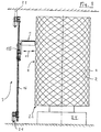
- FIG. 8 shows the mode of operation of a manipulator 3 in connection with a cylinder 22 storing good 5, the lateral surface of which forms the front of the shelf.
- the manipulator 3 can travel along a front front shelf 4 by means of two guide rails 21, which are attached, for example, to the ceiling and the floor.
- two guide rails 21, which are attached, for example, to the ceiling and the floor In the case shown here, only the front shelf 4 of an individual cylinder 22 can be seen, but at least one further cylinder 22 arranged behind the shown one is also conceivable, which is also operated by the manipulator 3 which can be moved parallel to the front shelf 4 .
- manipulator 3 in addition a flat, vertical front shelf too operated at least one cylinder rack.
- the guide column 16, on which a vertical unit 15 is guided, is located between the guide rails 21.
- the good receptacle 1 which exerts a substantially horizontally directed movement 25 for removal from the cylinder 22 or for equipping it.
- the honeycomb-like surface of the cylinder 22 with a plurality of shelf troughs 2 is achieved by creating crosswise helices. Another way of producing these shelf troughs 2 for a cylinder 22 is to deform round plates at their edges like a corrugated disk.
- the cylinder 22 has a preferably computer-controlled rotary drive 24. Thus, the manipulator 3 only needs the vertical and the assembly or. to complete the removal movement.
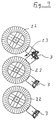
- the one shown above is on the drawing sheet Manipulator 3 also with one to the middle cylinder drawn “assistance” pivoted. If e.g. the middle manipulator 3 should fail, the upper cylinder 22 can be the 'neighboring' cylinder 22 "help out”.
- FIG. 1 Another development of the invention which is analogous to the embodiment variant according to FIGS. 5 and 6 is shown in FIG.
- a number of shelf troughs 2 arranged side by side are shown here as a section of a shelf.
- the good 5 is placed on finger 11 of the shelf recess.
- the goods 5 are already held by the fingers 10 of the goods receptacle 1 in the shelf trough 2 to the left and are raised for removal or loading.
- the fingers 10 of the goods receptacle 1, which in this embodiment variant were moved from the front of the shelf under the goods 5, are here, in the representation of a moment of a removal cycle, within the aisles 17 of the shelf recess 2; the fingers 10 of the good receptacle 1 and the fingers 22 of the shelf recess 2 intermesh like a comb.
Landscapes
- Engineering & Computer Science (AREA)
- Mechanical Engineering (AREA)
- Warehouses Or Storage Devices (AREA)
- Acyclic And Carbocyclic Compounds In Medicinal Compositions (AREA)
- Manipulator (AREA)
- Control And Other Processes For Unpacking Of Materials (AREA)
Abstract
Description
Da zukünftig Umverpackungen mehr und mehr entfallen sollen, hat sich dieses Vorurteil bisher weiter festgesetzt. Zudem war es bisher auch aus ästhetischen und traditionellen Gründen undenkbar, diesen ebenen Flächen - seien sie aus Glas oder aus einem anderen Werkstoff - noch ein funktionales oder sogar ein technisches Aussehen zu geben.
Ein Regalboden, der in neuer Art mit Vertiefungen in Form von Gassen oder mit Durchbrüchen in Form von Schlitzen versehen ist, die mindestens zur Entnahmefront des Regales, in der Regel dessen Vorderfront, offen sind, und der auch noch eine nichtebene Ober-/Auflagefläche aufweist, erfüllt einerseits dennoch die Erfordernisse des Arzneimittelbereiches und ermöglicht in Kombination mit der neuen Gestaltung des Manipulators zugleich eine schnellere Annäherung der Gut-Aufnhme an das zu entnehmende Gut.
Durch die neue Gestaltung des Regalbodens, insbesondere seiner Auflagefläche für das stückige Gut, sowie durch die neue Gut-Aufnahme, die mit zu den Vertiefungen korrespondierenden "Fingern" ausgestattet ist, sind für das Heranfahren des Manipulators und seiner Teile an die Position des Gutes gröbere Toleranzen beim Positionieren als bisher möglich; dieser Vorteil wirkt insbesondere positiv auf die Gesamt-Transportzeit für das Gut vom Regalfach bis zu einer vorgebbaren Position innerhalb der vorgesehenen Transportstrecke.
Die vorzugsweise und im wesentlichen V-förmig ausgebildete Positionsmulde hat eine selbstzentrierende Funktion für die Güter, deshalb braucht das Gut (die Ware) bei der Bestückung des Regales nicht mehr extrem genau plaziert werden.
Durch Einsatz eines einfachen Magazines, welches beispielsweise beim Transport zwischen Großhändler und Apotheker immer wieder im Austausch ist, wird ein weiterer Zeit- und Kostenvorteil erreicht.
Während bei einem Regal mit ebener Entnahmefront alle Bewegungen allein der Manipulator bewerkstelligen muß, "teilen" sich bei dieser erfindungsgemäßen Ausführung der Zylinder und der Manipulator die Wege. Etwaige Kräfte auf das Gut durch Beschleunigungs- oder Verzögerungskräfte durch die Zylinderdrehung bewirken wegen der vorzugsweise V-förmigen Ausformung der Mulde kein Verrutschen der Ware im Regalfach.
- Figur 1
- einen Querschnitt durch eine Gut-Aufnahme mit Schlitzen und durch eine Regalmulde mit Schlitzen, entlang der Schnittlinie A-A in Figur 2,
- Figur 2
- eine Draufsicht zu Figur 1,
- Figur 3
- einen Querschnitt durch eine Gut-Aufnahme mit Noppen und durch eine Regalmulde mit Schlitzen, entlang der Schnittlinie B-B in Figur 4,
- Figur 4
- eine Draufsicht zu Figur 3,
- Figur 5
- einen Querschnitt durch eine Gut-Aufnahme mit Schlitzen und durch eine Regalmulde mit Noppen, entlang der Schnittlinie C-C in Figur 6,
- Figur 6
- eine Draufsicht zu Figur 5,
- Figur 7
- eine stirnseitige Ansicht einer Mehrfach-Gut-Aufnahme,
- Figur 8
- einen Manipulator mit Gut-Zylinder,
- Figur 9
- eine reihenförmige Anordnung von Gut-Zylindern mit Manipulatoren,
- Figur 10
- eine zentrale Anordnung eines Manipulators zwischen vier Gut-Zylindern,
- Figur 11
- eine spezielle Ausgestaltung der in Figur 5 und 6 beschriebenen Ausführungsform und
- Figur 12
- ein Ausführungsbeispiel mit einer ebenen, geneigten Auflagefläche für Güter sowie eine zugeordnete Gut-Aufnahme.
Beim Heben bzw. Senken der Gut-Aufnahme 1 werden die Noppen 12, sinngemäß wie die Finger 10, durch die von Schlitzen 8 gebildeten Durchbrüche in der Regalmulde 2 zwischen deren Finger 11 hindurch geführt.
Die Breite "B" der Gut-Aufnahme 1, d.h. die Anzahl der Finger 10, ist hier so gewählt, daß die Gut-Aufnahme 1 Güter 5, 5', 5'' unterschiedlicher Breite aufnehmen kann.
Damit nur das betreffende vordere Gut entnommen wird, ist die Gut-Aufnahme zusätzlich in Positionierrichtung "P" verschiebbar, so daß nur die benötigte Anzahl von Fingern 10 der Gut-Aufnahme 1 das jeweilige, zu entnehmende Gut 5, 5' oder 5'' untergreifen.
Zur Verdeutlichung wurde die Gut-Aufnahme 1 und das Gut 5' in der Figur 12 nochmals in gestrichelter Darstellung gezeichnet. Nach der Entnahme des vorderen, hier des Gutes 5 rutschen dann die nachfolgenden Güter 5', 5'' zum Anschlag 18a der Auflagefläche 18 vor.
Die Breiten der Schlitze 8 und der Finger 10 sind hier so aufeinander abgestimmt, daß die Gut-Aufnahme 1 zur Entnahme des Gutes 5, 5', 5'' eine im wesentlichen vertikal gerichtete Hubbewegung H ausführen kann. Die Gut-Aufnahme 1 ist jedoch im speziellen zusätzlich in mehreren Achsen schwenkbar am Manipulator 3 gehaltert.
Bei einer Entnahme eines vorderen Gutes 5, rutschen die Nachfolgenden nach.
Um die Entnahme-Vorgänge zu realisieren, ist der Manipulator 3, insbesondere die Gut-Aufnahme 1 relativ zu dem am tiefsten Punkt der Regalmulde 2 liegenden Gut horizontal so positioniert, daß in Richtung der Regaltiefe die freien Enden der Finger 10 der Gut-Aufnahme 1 nach hinten nicht über das hintere Ende des aufzunehmenden Gutes hinausragen. Zudem ist die Gut-Aufnahme 1 in Weiterbildung vorzugsweise noch um mindestens eine Achse schwenkbar.
Die besagte Drehachse 14 kann, je nach konstruktiver Aufgabenstellung des Kunden, zugleich auch die Führungssäule 15 des Manipulators 3 sein. Je nach Größe des Gutes 5 wird, durch Drehung der Mehrfach-Gut-Aufnahme 13 um die Drehachse 14, eine Gut-Aufnahmen 1 mit einer zur Größe des jeweiligen Gutes 5 geeigneten Größe in Arbeitsposition gebracht.
Zur Entnahme (entsprechendes gilt auch bei Bestückung) eines Gutes 5 fährt die betreffende Gut-Aufnahme 1 parallel zur Drehachse 14 in Richtung zur Regalmulde 2 vor. Entweder allein durch diese Bewegung oder auch durch eine weitere Bewegung seitens des Manipulators 3, fährt die Gut-Aufnahme 1 unter das Gut 5. Die Drehbewegung der Mehrfach-Gut-Aufnahme 13 ist vorzugsweise rechnergesteuert.
Der Manipulator 3 kann mittels zweier Führungschienen 21, die beispielsweise an der Decke und am Boden angebracht sind, entlang einer Regal-Vorderfront 4 fahren.
In dem hier gezeigten Fall ist zwar nur die Regal-Vorderfront 4 eines einzelnen Zylinders 22 zu sehen, jedoch ist auch mindestens ein weiterer, hinter dem gezeigten angeordneter Zylinder 22 denkbar, der ebenfalls von dem parallel zur Regal-Vorderfront 4 verfahrbaren Manipulator 3 bedient wird.
Die wabenartige Oberfläche des Zylinders 22 mit einer Vielzahl von Regalmulden 2 wird erreicht, indem kreuzweise Wendeln angelegt werden.
Eine andere Art dieser Regalmulden 2 für einen Zylinder 22 herzustellen ist die, runde Platten an ihrem Rand ähnlich einer Wellscheibe zu verformen. Der Zylinder 22 besitzt einen vorzugsweise rechnergesteuerten Drehantrieb 24. Somit braucht der Manipulator 3 nur noch die vertikale und die Bestückungs-bzw. die Entnahmebewegung zu erledigen.
Durch seitliches verschieben der unmittelbar übereinander liegenden Reihen von Regalmulden um eine halbe Breite einer Regalmulde 2 sind eine Vielzahl von Regalmulden 2 sehr platzsparend in einer Regalebene anordbar.
- 1
- Gut-Aufnahme
- 1a
- Platte
- 2
- Regalmulde
- 2a
- Grundplatte
- 3
- Manipulator
- 4
- Regal-Vorderfront
- 5,5',5''
- Gut (Güter)
- 6
- Muldenmitte
- 7
- Aufnahmemitte
- 8
- Schlitze
- 9
- Anschlag (Anschläge an Pos. 11)
- 9a
- Anschlag (Anschläge an Pos. 2)
- 10
- Finger der Gut-Aufnahme
- 10a
- Anschlag an Pos. 10
- 11
- Finger der Regalmulde
- 12,12'
- Noppen
- 13
- Mehrfach-Gut-Aufnahme
- 14
- Drehachse
- 15
- vertikale Einheit
- 16
- Führungssäule
- 17
- Gasse
- 18
- Auflagefläche
- 18a
- Anschlag an Pos. 18
- 19
- Auflagepunkte
- 20a
- Auflagefläche an der Mehrfach-Gut-Aufnahme
- 20b
- Auflagefläche an der Mehrfach-Gut-Aufnahme
- 20c
- Auflagefläche an der Mehrfach-Gut-Aufnahme
- 20d
- Auflagefläche an der Mehrfach-Gut-Aufnahme
- 21
- Führungsschiene
- 22
- Zylinder
- 23
- Zwickel
- 24
- Drehantrieb
- 25
- Entnahme- bzw. Bestückungs-Bewegung
- P
- Positionierrichtung
- B
- Breite
- H
- Hubbewegung
Claims (27)
- Verfahren zum Auslagern von stückigem Gut in bzw. aus einem Regal mittels der Gut-Aufnahme (1) eines relativ zum Regal parallel sowie quer beweglichen Manipulators (3),
dadurch gekennzeichnet, daßdas Regal wenigstens eine Regalmulde (2) aufweist undzum Auslagern eines Gutes die Gut-Aufnahme (1) des Manipulators (3) von der RegalVorderfront (2) aus unter das Gut (5,5',5'') verbracht, zusammen mit dem Gut angehoben und nach vorne aus dem Regal heraus bewegt wird. - Verfahren nach Anspruch 1,
dadurch gekennzeichnet, daß
die Gut-Aufnahme (1) unter das Gut (5,5',5'') verbracht wird, indem sie zwischen die Regalmulde (2) und das Gut horizontal eingeschoben wird. - Verfahren nach Anspruch (1),
dadurch gekennzeichnet, daß
die Gut-Aufnahme (1) unter das Gut (5,5',5'') verbracht wird, indem sie von unten nach oben die Regalmulde (2) durchläuft. - Verfahren nach einem der vorhergehenden Ansprüche,
dadurch gekennzeichnet, daß
das Einlagern im umgekehrten Ablauf wie das Auslagern geschieht. - Verfahren nach einem der vorhergehenden Ansprüche,
dadurch gekennzeichnet, daß
das Einlagern auch von der Vorderseite des Regales (4) her geschieht. - Verfahren nach einem der vorhergehenden Ansprüche, insbesondere zum Ein- und Auslagern
dadurch gekennzeichnet, daß
die Parallelbewegung zwischen Regal und Manipulator durch Bewegung des Regales, insbesondere durch Rotation eines runden Regales (22), erzielt wird. - Verfahren nach einem der vorhergehenden Ansprüche,
dadurch gekennzeichnet, daß
beim Auslagern mehrerer stückiger Güter, welche häufig in dieser Kombination benötigt werden, der Gutaufnehmer (1) des Manipulators (3) mehrere Regalmulden (2) nacheinander vertikal durchläuft. - Verfahren nach einem der vorhergehenden Ansprüche,
dadurch gekennzeichnet, daß
bei mehreren in einer Regalmulde (2) eingelegten Gütern diese so eingelegt sind, daß die Güter zum Tiefpunkt der Regalmulde (2) hin nachrutschen können. - Verfahren nach Anspruch 8,
dadurch gekennzeichnet, daß
sich das zweite und die folgenden Güter nur in Richtung des insbesondere schräg nach hinten ansteigenden Muldenverlaufes an dem am tiefsten Punkt der Regalmulde (2) liegenden Gut anschließen und für das Auslagern der Manipulator relativ zu dem am tiefsten Punkt der Regalmulde (2) liegenden Gut horizontal so positioniert ist, daß in Richtung der Regaltiefe die freien Enden der Finger(10) der Gut-Aufnahme nach hinten nicht über das hintere Ende des aufzunehmenden Gutes hinausragen. - Verfahren nach Anspruch 8,
dadurch gekennzeichnet, daß
sich das zweite und die folgenden Güter nur auf einer Seite des Muldenverlaufes an dem am tiefsten Punkt der Regalmulde (2) liegenden Gut anschließen und für das Auslagern der Manipulator relativ zu dem am tiefsten Punkt der Regalmulde liegenden Gut horizontal so positioniert ist, daß in Richtung des zweiten und der folgenden Güter die Seitenkante des Manipulators (3) nicht über das aufzunehmende Gut hinaus ragt. - Vorrichtung zur Durchführung des Verfahrens nach mindestens einem der Verfahrensansprüchedadurch gekennzeichnet, daßmit einem Regal,einem Manipulator (3) mit einer Gut-Aufnahme (1) zum Ein- und Auslagern von stückigem Gut im bzw. aus dem Regal,
das Regal Regalmulden (2) aufweist, sowie Gassen (17), um die Gut-Aufnahme (1) des Manipulators (3) unter das in der Regalmulde (2) befindliche Gut bringen zu können. - Vorrichtung nach einem der vorhergehenden Vorrichtungsansprüche,
dadurch gekennzeichnet, daß
die Gassen (17) aus zur Vorderfront hin offenen Vertiefungen in der Auflagefläche (18) der Regalmulde (2) bestehen und die Gut-Aufnahme (1) aus Fingern (10), deren Abstand und Dimension den Vertiefungen der Regalmulde (2) entspricht. - Vorrichtung nach einem der vorhergehenden Vorrichtungsansprüche,
dadurch gekennzeichnet, daß
die Gassen (17) aus sich bis zur Vorderfront erstreckenden, von der Auflagefläche (18) zur Unterseite des Regalbodens durchgehenden, Schlitzen (8) bestehen und die Gut-Aufnahme (1) des Manipulators (1) aus Fingern (10), deren Abstand und Dimension den Schlitzen (8) der Regalmulde (2) entspricht. - Vorrichtung nach einem der vorhergehenden Vorrichtungsansprüche,
dadurch gekennzeichnet, daß
der Manipulator (3) parallel zur Vorderfront (4) des Regales verfahrbar angeordnet ist. - Vorrichtung nach einem der vorhergehenden Vorrichtungsansprüche,
dadurch gekennzeichnet, daß
die Regalmulde (2) und/oder die Gut-Aufnahme (1) V-förmig ausgebildet ist. - Vorrichtung nach einem der vorhergehenden Vorrichtungsansprüche,
dadurch gekennzeichnet,
daß die Auflagefläche (18) mindestens der Regalmulde (2) und/oder der Gut-Aufnahme (1) aus - im Verhältnis zur einzelnen Gassengröße - kleinflächigen Auflagepunkten (19) besteht. - Vorrichtung nach einem der vorhergehenden Vorrichtungsansprüche,
dadurch gekennzeichnet,
daß die Auflagefläche (18) mindestens der Regalmulde (2) und/oder der Gut-Aufnahme (1), eine rutschhemmende Oberfläche aufweisen. - Vorrichtung nach einem der vorhergehenden Vorrichtungsansprüche,
dadurch gekennzeichnet,
daß die Auflagefläche (18) mindestens der Regalmulde (2) an ihrer Vorderfront einen im wesentlichen senkrechten Anschlag (9a, 18a) für das Gut (5) aufweisen. - Vorrichtung nach einem der vorhergehenden Vorrichtungsansprüche,
dadurch gekennzeichnet,
daß die Gut-Aufnahme (1) verschiedene Auflageflächen (20 a,b,c,d) besitzt, die um eine waagerechte Achse (14) drehbar gelagert sind. - Vorrichtung nach einem der vorhergehenden Vorrichtungsansprüche,
dadurch gekennzeichnet,
daß mindestens eine Auflagefläche (18) der Gut-Aufnahme (1) derart um eine vertikale Achse, insbesondere eine Führungssäule (16), schwenkbar ist, so daß die Hauptachse des V-förmigen Querschnittes der Auflagefläche im wesentlichen senkrecht auf die Regal-Vorderfront (4) weist. - Vorrichtung nach einem der vorhergehenden Vorrichtungsansprüche,
dadurch gekennzeichnet,
daß die Gut-Aufnahme (1) eine Ablagefläche, insbesondere im Bereich ihrer Anbindung an die Führungssäule (16), besitzt. - Vorrichtung nach einem der vorhergehenden Vorrichtungsansprüche,
dadurch gekennzeichnet,
daß das Regal mindestens ein stehender, drehbarer, insbesondere rechnergesteuerter Zylinder (22) ist und die Regal-Vorderfront (4) die Mantelfläche des Zylinders. - Vorrichtung nach einem der vorhergehenden Vorrichtungsansprüche,
dadurch gekennzeichnet,
daß die Regalmulden (2) des Zylinders (22) aus sich kreuzenden, wendelförmig entlang der Mantelfläche ansteigenden Regalböden gebildet werden. - Vorrichtung nach einem der vorhergehenden Vorrichtungsansprüche,
dadurch gekennzeichnet,
daß die Regalmulden (2) des Zylinders (22) aus übereinander liegenden Scheiben gebildet werden, deren Umfangs-Ränder V-förmige Vertiefungen aufweisen. - Vorrichtung nach einem der vorhergehenden Vorrichtungsansprüche,
dadurch gekennzeichnet,
daß die Regal-Vorderfront (4) aus mindestens einer ebenen und senkrechten Fläche besteht. - Vorrichtung nach einem der vorhergehenden Vorrichtungsansprüche,
dadurch gekennzeichnet,
daß der Manipulator (3) mit seiner Führungssäule (16) ortsfest im Zwickel (23) zwischen mindestens zwei Zylindern (22) angeordnet ist. - Vorrichtung nach einem der vorhergehenden Vorrichtungsansprüche,
dadurch gekennzeichnet,
daß die Regal-Vorderfront (4) aus mindestens einem Zylinder (22) und/oder mindestens einem ebenen Regal gebildet wird.
Applications Claiming Priority (2)
| Application Number | Priority Date | Filing Date | Title |
|---|---|---|---|
| DE19844896A DE19844896A1 (de) | 1998-09-30 | 1998-09-30 | Verfahren und Vorrichtung zur Handhabung von stückigem Gut, insbesondere von Arzneimitteln |
| DE19844896 | 1998-09-30 |
Publications (3)
| Publication Number | Publication Date |
|---|---|
| EP0997401A2 true EP0997401A2 (de) | 2000-05-03 |
| EP0997401A3 EP0997401A3 (de) | 2000-08-16 |
| EP0997401B1 EP0997401B1 (de) | 2006-06-14 |
Family
ID=7882835
Family Applications (1)
| Application Number | Title | Priority Date | Filing Date |
|---|---|---|---|
| EP99118904A Expired - Lifetime EP0997401B1 (de) | 1998-09-30 | 1999-09-24 | Verfahren und Vorrichtung zur Handhabung von stückigem Gut, insbesondere von Arzneimitteln |
Country Status (5)
| Country | Link |
|---|---|
| EP (1) | EP0997401B1 (de) |
| AT (1) | ATE329863T1 (de) |
| DE (2) | DE19844896A1 (de) |
| DK (1) | DK0997401T3 (de) |
| ES (1) | ES2267216T3 (de) |
Cited By (3)
| Publication number | Priority date | Publication date | Assignee | Title |
|---|---|---|---|---|
| GB2374339A (en) * | 2001-02-21 | 2002-10-16 | Daifuku Kk | Materials handling system |
| CN111169886A (zh) * | 2020-02-14 | 2020-05-19 | 常州机电职业技术学院 | 一种旋转悬挂式仓储中心 |
| CN115321075A (zh) * | 2022-09-21 | 2022-11-11 | 珠海华做智能技术有限公司 | 一种可换仓、可滑动、可旋转的双工位快件仓储机构 |
Families Citing this family (3)
| Publication number | Priority date | Publication date | Assignee | Title |
|---|---|---|---|---|
| DE10233276A1 (de) * | 2002-07-23 | 2004-02-05 | Sympat Gmbh | Speicherturm |
| GB2394078A (en) * | 2002-10-08 | 2004-04-14 | Retail Experience Ltd | Stock Movement Control |
| DE102004059809B4 (de) * | 2004-12-10 | 2010-09-09 | Lang, Hartmut | Verfahren und Vorrichtung zur Bestückung und Entnahme von Lagergut aus Regalfächern eines Lagerregals |
Family Cites Families (7)
| Publication number | Priority date | Publication date | Assignee | Title |
|---|---|---|---|---|
| FR2160722B1 (de) * | 1971-11-23 | 1974-12-20 | Japan National Railway | |
| DE3424521A1 (de) * | 1984-07-04 | 1986-01-16 | Oxytechnik Gesellschaft für Systemtechnik mbH, 6236 Eschborn | Rohrsilo |
| DE3532181A1 (de) * | 1985-09-10 | 1987-03-12 | Dudweiler Untertage Masch | Einrichtung zur lagerung von paletten u.dgl. |
| JPH03177206A (ja) * | 1989-12-02 | 1991-08-01 | Sumitomo Rubber Ind Ltd | 物品の取り出し・格納方法と装置 |
| DE9315118U1 (de) * | 1993-10-06 | 1993-12-16 | M. Staude GmbH, 46485 Wesel | Komissionierungsanlage für Apothekenprodukte |
| DE9319655U1 (de) * | 1993-12-21 | 1994-03-03 | P+P Elektronik GmbH, 90765 Fürth | Regaleinrichtung für ein Kommissioniergestell |
| DE9413114U1 (de) * | 1994-08-13 | 1994-11-17 | Lesti, Klaus, 86508 Rehling | Hochregallager |
-
1998
- 1998-09-30 DE DE19844896A patent/DE19844896A1/de not_active Withdrawn
-
1999
- 1999-09-24 ES ES99118904T patent/ES2267216T3/es not_active Expired - Lifetime
- 1999-09-24 DE DE59913551T patent/DE59913551D1/de not_active Expired - Fee Related
- 1999-09-24 AT AT99118904T patent/ATE329863T1/de not_active IP Right Cessation
- 1999-09-24 EP EP99118904A patent/EP0997401B1/de not_active Expired - Lifetime
- 1999-09-24 DK DK99118904T patent/DK0997401T3/da active
Cited By (4)
| Publication number | Priority date | Publication date | Assignee | Title |
|---|---|---|---|---|
| GB2374339A (en) * | 2001-02-21 | 2002-10-16 | Daifuku Kk | Materials handling system |
| GB2374339B (en) * | 2001-02-21 | 2004-01-21 | Daifuku Kk | Materials handling system |
| CN111169886A (zh) * | 2020-02-14 | 2020-05-19 | 常州机电职业技术学院 | 一种旋转悬挂式仓储中心 |
| CN115321075A (zh) * | 2022-09-21 | 2022-11-11 | 珠海华做智能技术有限公司 | 一种可换仓、可滑动、可旋转的双工位快件仓储机构 |
Also Published As
| Publication number | Publication date |
|---|---|
| ATE329863T1 (de) | 2006-07-15 |
| ES2267216T3 (es) | 2007-03-01 |
| EP0997401B1 (de) | 2006-06-14 |
| DK0997401T3 (da) | 2006-10-16 |
| DE59913551D1 (de) | 2006-07-27 |
| EP0997401A3 (de) | 2000-08-16 |
| DE19844896A1 (de) | 2000-04-06 |
Similar Documents
| Publication | Publication Date | Title |
|---|---|---|
| DE3920405C1 (de) | ||
| DE68919261T2 (de) | Verfahren und Vorrichtung zum Kommissionieren von Artikeln bei Umdrehen einer Verpackung. | |
| EP0860382B1 (de) | Kommossionierverfahren sowie Kommissionieranlage zur Durchführung des Verfahrens | |
| DE4416103C2 (de) | Hochregal | |
| EP3889076B1 (de) | Kommissioniersystem und kommissionierverfahren | |
| DE10136354A1 (de) | Verfahren und Anlage zum Kommissionieren mit einem Behälterregal und zugeordnetem Regalbediengerät | |
| DE4336885A1 (de) | Kommissionierungsanlage für Apothekenprodukte | |
| DE20112328U1 (de) | Kommissionieranlage mit einem Behälterregal und zugeordnetem Regalbediengerät | |
| DE29723878U1 (de) | Vorrichtung zum Kommissionieren | |
| DE19849391A1 (de) | Kistenstapellager | |
| DE2608393A1 (de) | Foerderanlage | |
| DE60208560T2 (de) | Ein lagersystem und ein verfahren zum zeitlichen speichern von gegenständen | |
| WO1994007775A1 (de) | Vorrichtung zum ein- und auslagern von lastträgern in ein regal bzw. aus einem regal | |
| EP1818282B1 (de) | Verfahren zum Auslagern von Stückgütern aus einem automatisierten Stückgut-Lager | |
| EP0997401B1 (de) | Verfahren und Vorrichtung zur Handhabung von stückigem Gut, insbesondere von Arzneimitteln | |
| DE102004025070C5 (de) | Verfahren und Vorrichtung zur Einlagerung von Waren in eine automatisierte Lagervorrichtung | |
| DE29805946U1 (de) | Regallagersystem für Stückgut, insbesondere für die Kommissionierung von Arzneimittelpackungen | |
| DE29701565U1 (de) | Behälter-Sortierpuffer für eine Kommissionieranlage | |
| DE19719651A1 (de) | Verfahren und Vorrichtung zum Kommissionieren | |
| DE102015113401A1 (de) | Ausgabeeinheit für Backwaren | |
| EP1524209B1 (de) | Verfahren und Vorrichtung zum gleichzeitigen Auslagern mehrerer Stückgüter aus einem automatisierung Regallager | |
| EP0416627B1 (de) | Verfahren und Vorrichtung zum Lagern in und zum automatischen Entnehmen von Stückgutsorten aus Regalen in Grosslagern | |
| DE102022115014A1 (de) | Lagerlift mit optimierter Kommissionierleistung | |
| EP3272678B1 (de) | Kommissioniersystem und verfahren zur auslagerung von objekten aus einem kommissioniersystem | |
| DE202016103890U1 (de) | Kommissioniersystem |
Legal Events
| Date | Code | Title | Description |
|---|---|---|---|
| PUAI | Public reference made under article 153(3) epc to a published international application that has entered the european phase |
Free format text: ORIGINAL CODE: 0009012 |
|
| AK | Designated contracting states |
Kind code of ref document: A2 Designated state(s): AT BE CH CY DE DK ES FI FR GB GR IE IT LI LU MC NL PT SE |
|
| AX | Request for extension of the european patent |
Free format text: AL;LT;LV;MK;RO;SI |
|
| PUAL | Search report despatched |
Free format text: ORIGINAL CODE: 0009013 |
|
| RIC1 | Information provided on ipc code assigned before grant |
Free format text: 7B 65G 1/04 A, 7B 65G 1/02 B, 7B 65G 1/137 B |
|
| AK | Designated contracting states |
Kind code of ref document: A3 Designated state(s): AT BE CH CY DE DK ES FI FR GB GR IE IT LI LU MC NL PT SE |
|
| AX | Request for extension of the european patent |
Free format text: AL;LT;LV;MK;RO;SI |
|
| 17P | Request for examination filed |
Effective date: 20010215 |
|
| AKX | Designation fees paid |
Free format text: AT BE CH CY DE DK ES FI FR GB GR IE IT LI LU MC NL PT SE |
|
| RAP1 | Party data changed (applicant data changed or rights of an application transferred) |
Owner name: SWISSLOG (DEUTSCHLAND) GMBH |
|
| RIN1 | Information on inventor provided before grant (corrected) |
Inventor name: LANG, HARTMUT |
|
| 17Q | First examination report despatched |
Effective date: 20030306 |
|
| GRAP | Despatch of communication of intention to grant a patent |
Free format text: ORIGINAL CODE: EPIDOSNIGR1 |
|
| GRAS | Grant fee paid |
Free format text: ORIGINAL CODE: EPIDOSNIGR3 |
|
| GRAA | (expected) grant |
Free format text: ORIGINAL CODE: 0009210 |
|
| AK | Designated contracting states |
Kind code of ref document: B1 Designated state(s): AT BE CH CY DE DK ES FI FR GB GR IE IT LI LU MC NL PT SE |
|
| PG25 | Lapsed in a contracting state [announced via postgrant information from national office to epo] |
Ref country code: IE Free format text: LAPSE BECAUSE OF FAILURE TO SUBMIT A TRANSLATION OF THE DESCRIPTION OR TO PAY THE FEE WITHIN THE PRESCRIBED TIME-LIMIT Effective date: 20060614 Ref country code: FI Free format text: LAPSE BECAUSE OF FAILURE TO SUBMIT A TRANSLATION OF THE DESCRIPTION OR TO PAY THE FEE WITHIN THE PRESCRIBED TIME-LIMIT Effective date: 20060614 |
|
| REG | Reference to a national code |
Ref country code: GB Ref legal event code: FG4D Free format text: NOT ENGLISH |
|
| REG | Reference to a national code |
Ref country code: CH Ref legal event code: EP |
|
| REG | Reference to a national code |
Ref country code: IE Ref legal event code: FG4D Free format text: LANGUAGE OF EP DOCUMENT: GERMAN |
|
| REF | Corresponds to: |
Ref document number: 59913551 Country of ref document: DE Date of ref document: 20060727 Kind code of ref document: P |
|
| PGFP | Annual fee paid to national office [announced via postgrant information from national office to epo] |
Ref country code: LU Payment date: 20060809 Year of fee payment: 8 |
|
| PGFP | Annual fee paid to national office [announced via postgrant information from national office to epo] |
Ref country code: BE Payment date: 20060818 Year of fee payment: 8 |
|
| PGFP | Annual fee paid to national office [announced via postgrant information from national office to epo] |
Ref country code: AT Payment date: 20060825 Year of fee payment: 8 |
|
| REG | Reference to a national code |
Ref country code: CH Ref legal event code: NV Representative=s name: RENTSCH & PARTNER |
|
| PGFP | Annual fee paid to national office [announced via postgrant information from national office to epo] |
Ref country code: DK Payment date: 20060911 Year of fee payment: 8 |
|
| REG | Reference to a national code |
Ref country code: SE Ref legal event code: TRGR |
|
| PGFP | Annual fee paid to national office [announced via postgrant information from national office to epo] |
Ref country code: DE Payment date: 20060915 Year of fee payment: 8 |
|
| PGFP | Annual fee paid to national office [announced via postgrant information from national office to epo] |
Ref country code: FR Payment date: 20060922 Year of fee payment: 8 |
|
| GBT | Gb: translation of ep patent filed (gb section 77(6)(a)/1977) |
Effective date: 20060831 |
|
| PGFP | Annual fee paid to national office [announced via postgrant information from national office to epo] |
Ref country code: ES Payment date: 20060927 Year of fee payment: 8 |
|
| PG25 | Lapsed in a contracting state [announced via postgrant information from national office to epo] |
Ref country code: MC Free format text: LAPSE BECAUSE OF NON-PAYMENT OF DUE FEES Effective date: 20060930 |
|
| PGFP | Annual fee paid to national office [announced via postgrant information from national office to epo] |
Ref country code: IT Payment date: 20060930 Year of fee payment: 8 |
|
| PGFP | Annual fee paid to national office [announced via postgrant information from national office to epo] |
Ref country code: GB Payment date: 20061002 Year of fee payment: 8 |
|
| REG | Reference to a national code |
Ref country code: DK Ref legal event code: T3 |
|
| PG25 | Lapsed in a contracting state [announced via postgrant information from national office to epo] |
Ref country code: PT Free format text: LAPSE BECAUSE OF FAILURE TO SUBMIT A TRANSLATION OF THE DESCRIPTION OR TO PAY THE FEE WITHIN THE PRESCRIBED TIME-LIMIT Effective date: 20061114 |
|
| PGFP | Annual fee paid to national office [announced via postgrant information from national office to epo] |
Ref country code: CH Payment date: 20061213 Year of fee payment: 8 |
|
| ET | Fr: translation filed | ||
| REG | Reference to a national code |
Ref country code: ES Ref legal event code: FG2A Ref document number: 2267216 Country of ref document: ES Kind code of ref document: T3 |
|
| PG25 | Lapsed in a contracting state [announced via postgrant information from national office to epo] |
Ref country code: NL Free format text: LAPSE BECAUSE OF NON-PAYMENT OF DUE FEES Effective date: 20070401 |
|
| PLBE | No opposition filed within time limit |
Free format text: ORIGINAL CODE: 0009261 |
|
| STAA | Information on the status of an ep patent application or granted ep patent |
Free format text: STATUS: NO OPPOSITION FILED WITHIN TIME LIMIT |
|
| 26N | No opposition filed |
Effective date: 20070315 |
|
| NLV4 | Nl: lapsed or anulled due to non-payment of the annual fee |
Effective date: 20070401 |
|
| PGFP | Annual fee paid to national office [announced via postgrant information from national office to epo] |
Ref country code: SE Payment date: 20060901 Year of fee payment: 8 |
|
| BERE | Be: lapsed |
Owner name: *SWISSLOG (DEUTSCHLAND) G.M.B.H. Effective date: 20070930 |
|
| PG25 | Lapsed in a contracting state [announced via postgrant information from national office to epo] |
Ref country code: SE Free format text: LAPSE BECAUSE OF NON-PAYMENT OF DUE FEES Effective date: 20070925 Ref country code: GR Free format text: LAPSE BECAUSE OF FAILURE TO SUBMIT A TRANSLATION OF THE DESCRIPTION OR TO PAY THE FEE WITHIN THE PRESCRIBED TIME-LIMIT Effective date: 20060915 |
|
| REG | Reference to a national code |
Ref country code: DK Ref legal event code: EBP |
|
| REG | Reference to a national code |
Ref country code: CH Ref legal event code: PL |
|
| EUG | Se: european patent has lapsed | ||
| GBPC | Gb: european patent ceased through non-payment of renewal fee |
Effective date: 20070924 |
|
| PG25 | Lapsed in a contracting state [announced via postgrant information from national office to epo] |
Ref country code: AT Free format text: LAPSE BECAUSE OF NON-PAYMENT OF DUE FEES Effective date: 20070924 |
|
| PG25 | Lapsed in a contracting state [announced via postgrant information from national office to epo] |
Ref country code: LI Free format text: LAPSE BECAUSE OF NON-PAYMENT OF DUE FEES Effective date: 20070930 Ref country code: DE Free format text: LAPSE BECAUSE OF NON-PAYMENT OF DUE FEES Effective date: 20080401 Ref country code: CH Free format text: LAPSE BECAUSE OF NON-PAYMENT OF DUE FEES Effective date: 20070930 |
|
| PG25 | Lapsed in a contracting state [announced via postgrant information from national office to epo] |
Ref country code: BE Free format text: LAPSE BECAUSE OF NON-PAYMENT OF DUE FEES Effective date: 20070930 |
|
| REG | Reference to a national code |
Ref country code: FR Ref legal event code: ST Effective date: 20080531 |
|
| PG25 | Lapsed in a contracting state [announced via postgrant information from national office to epo] |
Ref country code: FR Free format text: LAPSE BECAUSE OF NON-PAYMENT OF DUE FEES Effective date: 20071001 Ref country code: DK Free format text: LAPSE BECAUSE OF NON-PAYMENT OF DUE FEES Effective date: 20071001 |
|
| PG25 | Lapsed in a contracting state [announced via postgrant information from national office to epo] |
Ref country code: GB Free format text: LAPSE BECAUSE OF NON-PAYMENT OF DUE FEES Effective date: 20070924 Ref country code: CY Free format text: LAPSE BECAUSE OF FAILURE TO SUBMIT A TRANSLATION OF THE DESCRIPTION OR TO PAY THE FEE WITHIN THE PRESCRIBED TIME-LIMIT Effective date: 20060614 |
|
| REG | Reference to a national code |
Ref country code: ES Ref legal event code: FD2A Effective date: 20070925 |
|
| PG25 | Lapsed in a contracting state [announced via postgrant information from national office to epo] |
Ref country code: ES Free format text: LAPSE BECAUSE OF NON-PAYMENT OF DUE FEES Effective date: 20070925 |
|
| PG25 | Lapsed in a contracting state [announced via postgrant information from national office to epo] |
Ref country code: LU Free format text: LAPSE BECAUSE OF NON-PAYMENT OF DUE FEES Effective date: 20070924 Ref country code: IT Free format text: LAPSE BECAUSE OF NON-PAYMENT OF DUE FEES Effective date: 20070924 |