EP0997418B1 - Méthode et dispositif pour couper une bande en déplacement - Google Patents
Méthode et dispositif pour couper une bande en déplacement Download PDFInfo
- Publication number
- EP0997418B1 EP0997418B1 EP99114488A EP99114488A EP0997418B1 EP 0997418 B1 EP0997418 B1 EP 0997418B1 EP 99114488 A EP99114488 A EP 99114488A EP 99114488 A EP99114488 A EP 99114488A EP 0997418 B1 EP0997418 B1 EP 0997418B1
- Authority
- EP
- European Patent Office
- Prior art keywords
- severing
- web
- roll
- blown air
- elements
- Prior art date
- Legal status (The legal status is an assumption and is not a legal conclusion. Google has not performed a legal analysis and makes no representation as to the accuracy of the status listed.)
- Expired - Lifetime
Links
- 238000000034 method Methods 0.000 title claims description 10
- 238000004804 winding Methods 0.000 claims abstract description 41
- 238000005520 cutting process Methods 0.000 claims abstract description 20
- 230000001360 synchronised effect Effects 0.000 abstract 1
- 239000000463 material Substances 0.000 description 42
- 238000000926 separation method Methods 0.000 description 30
- 238000007664 blowing Methods 0.000 description 21
- 230000002093 peripheral effect Effects 0.000 description 3
- 239000003795 chemical substances by application Substances 0.000 description 2
- 235000013290 Sagittaria latifolia Nutrition 0.000 description 1
- 241001417494 Sciaenidae Species 0.000 description 1
- 230000003213 activating effect Effects 0.000 description 1
- 235000015246 common arrowhead Nutrition 0.000 description 1
- 230000006735 deficit Effects 0.000 description 1
- 230000000694 effects Effects 0.000 description 1
- 230000002349 favourable effect Effects 0.000 description 1
- 238000003825 pressing Methods 0.000 description 1
- XLYOFNOQVPJJNP-UHFFFAOYSA-N water Substances O XLYOFNOQVPJJNP-UHFFFAOYSA-N 0.000 description 1
Images


Classifications
-
- B—PERFORMING OPERATIONS; TRANSPORTING
- B65—CONVEYING; PACKING; STORING; HANDLING THIN OR FILAMENTARY MATERIAL
- B65H—HANDLING THIN OR FILAMENTARY MATERIAL, e.g. SHEETS, WEBS, CABLES
- B65H19/00—Changing the web roll
- B65H19/22—Changing the web roll in winding mechanisms or in connection with winding operations
- B65H19/26—Cutting-off the web running to the wound web roll
-
- B—PERFORMING OPERATIONS; TRANSPORTING
- B26—HAND CUTTING TOOLS; CUTTING; SEVERING
- B26D—CUTTING; DETAILS COMMON TO MACHINES FOR PERFORATING, PUNCHING, CUTTING-OUT, STAMPING-OUT OR SEVERING
- B26D3/00—Cutting work characterised by the nature of the cut made; Apparatus therefor
- B26D3/10—Making cuts of other than simple rectilinear form
-
- B—PERFORMING OPERATIONS; TRANSPORTING
- B26—HAND CUTTING TOOLS; CUTTING; SEVERING
- B26F—PERFORATING; PUNCHING; CUTTING-OUT; STAMPING-OUT; SEVERING BY MEANS OTHER THAN CUTTING
- B26F3/00—Severing by means other than cutting; Apparatus therefor
- B26F3/002—Precutting and tensioning or breaking
-
- B—PERFORMING OPERATIONS; TRANSPORTING
- B26—HAND CUTTING TOOLS; CUTTING; SEVERING
- B26F—PERFORATING; PUNCHING; CUTTING-OUT; STAMPING-OUT; SEVERING BY MEANS OTHER THAN CUTTING
- B26F3/00—Severing by means other than cutting; Apparatus therefor
- B26F3/02—Tearing
-
- B—PERFORMING OPERATIONS; TRANSPORTING
- B65—CONVEYING; PACKING; STORING; HANDLING THIN OR FILAMENTARY MATERIAL
- B65H—HANDLING THIN OR FILAMENTARY MATERIAL, e.g. SHEETS, WEBS, CABLES
- B65H2301/00—Handling processes for sheets or webs
- B65H2301/50—Auxiliary process performed during handling process
- B65H2301/51—Modifying a characteristic of handled material
- B65H2301/515—Cutting handled material
- B65H2301/5151—Cutting handled material transversally to feeding direction
-
- B—PERFORMING OPERATIONS; TRANSPORTING
- B65—CONVEYING; PACKING; STORING; HANDLING THIN OR FILAMENTARY MATERIAL
- B65H—HANDLING THIN OR FILAMENTARY MATERIAL, e.g. SHEETS, WEBS, CABLES
- B65H2408/00—Specific machines
- B65H2408/20—Specific machines for handling web(s)
- B65H2408/23—Winding machines
- B65H2408/236—Pope-winders with first winding on an arc of circle and secondary winding along rails
Definitions
- the present invention relates to a method for severing a running material web, in particular a paper web in a winding device when changing the reel, in which a separating device between a winding roller and an empty reel on the one hand and a drum carrying a wrap formed in the device on the other hand, is moved into the web path, the material web by having a plurality of separating elements arranged side by side Separating device across the width of the material web one after the other is severed in several places, and a device for Implementation of such a procedure.
- Winding devices of the type mentioned here are, for example used at the end of a machine to produce a material web and serve for the continuous winding of the material web on one Tambour. After completing a wrap, that is, after reaching it a desired winding diameter, the material web must be cut and the previous drum is replaced by an empty drum, on which the next roll is then formed. exceptionally a reel change can take place when the winding is still has not reached the normally desired diameter.
- a method and an apparatus for performing such Drum changes are from PCT publication WO 96/11868 known.
- the entire is used to cut the paper web Knife blade spanning web width used for cutting the paper web from a rest position in the path of the paper web is moved.
- the German published application DE-OS 23 01 193 discloses a device for changing rolls and cross cutting high-speed ones Sheets in multiple winding machines. This is a cut a rigid toothed cutting knife between the running material web a winding roller and an empty reel on the one hand and an in the device formed reel carrying reel on the other hand in the Web path moves, the web of material through the toothed cutting knife across the width of the material web in succession in several places is severed.
- the straight dividing line runs in relation to the Material web along a line inclined to the web running direction.
- a blow pipe is located at a distance from the toothed cutting knife, which put the tip of the new start of the path on the empty sleeve should.
- German patent application DE 44 01 804 A1 discloses Process using a spanning the entire web width Separating device, in particular a knife blade, for cutting the paper web from a rest position in the path of the paper web is moved. There is a web-wide severing of the running paper web when generating a perpendicular to the direction of the Material web running dividing line instead, with the running paper web severed without making a transfer strip and then by means of a blow pipe against the outer surface of the new one Drum is blown.
- the present invention has for its object an improved Method of the type mentioned and an apparatus for carrying it out to specify such a procedure.
- This object is achieved in that the separation points based on the Material web inclined along one to the web running direction and zigzag lie over the line width and that the through the Separation process created new web start of the material web by means of Area of the separating elements of blowing air escaping in the direction of the Empty drum is moved.
- the material web is severed in such a way that that there is a separating edge inclined to the web running direction results.
- the new beginning of the path is blown in with Moved towards the empty reel. This can ensure a safe performance guaranteed at the start of the web on the empty reel.
- a device is used to carry out the method according to the invention used, which is characterized in that the separating elements on a substantially extending over the width of the web Separating device are arranged, which starting from a rest position in a separation position and is movable back, wherein the separators are arranged so that they move when moving the separator several separation points in succession in the separation position generate, based on the material web along one to the web running direction inclined and zigzag across the width of the web Line lie and that on the separators blowing air nozzles for support the performance of the new beginning of the material web on the empty reel.
- the separating device is in the form of a supporting beam, arranged on the side of the material web facing away from the empty reel is trained.
- the supporting beam is of this type pivoted that the release agent with the in the direction of web looks at the forefront one after the other on the material web act. This configuration ensures a complete and clean Separation of the material web across the entire width.
- the separating device is according to a second embodiment as one Rotationally driven separating roller, on the roller shell of several separating elements are arranged along at least one spiral line.
- the peripheral speed of the separation roller can be the web running speed correspond, but it can also be smaller or larger than these be.
- the arrangement of the separating roller on the is also particularly suitable the side of the material web facing away from the empty drum.
- the movement of the The separation roller between the rest position and the separation position can be without Impairment of the empty reel.
- the blowing air nozzles can each according to an embodiment of the invention arranged directly next to a separating element on the separating roller and from Blowing air can be applied to the inside of the separating roller.
- a other embodiment of the invention can on the outside of the Roller jacket of the separating roller but also one or more blow air pipes be provided with blowing air nozzles.
- the air volume is thereby advantageously kept low. This results in a quick build-up of pressure and also has the advantage that the leakage air loss is reduced.
- the blown air pipes are preferably parallel to the separating elements arranged in a spiral line. The blown air thus has an advantageous effect directly at the respective separating edge.
- the separating elements are along several, alternating in opposite directions and arranged over the roller width of contiguous spiral lines. This configuration enables a zigzag-shaped separating edge to be produced , the tips of which, depending on the arrangement of the spiral lines in Point the web running direction or in the opposite direction.
- the spiral lines can be one or more times the circumference of the Include separation roller. But it is also possible to provide the spiral lines in such a way that they only cover part of the circumference of the separating roller.
- This embodiment has the advantage that the separation roller with its Separating elements free area are first created on the material web can. The timing of the creation and rotation of the This makes the separating roller easier.
- control means are provided through which the separating roller can be successively set in rotation, the blowing air nozzles can be charged with blowing air and the separating roller is movable into its disconnected position, the action on the blowing air nozzles with blowing air, preferably immediately before immersing the Separating roller into the web of material. Accordingly, in reverse Order the separating roller moves back to its starting position, the rotation of the separation roller stopped and the blowing air switched off.
- the Separation process can hereby be automated in an advantageous manner.
- control means are provided by which it is ensured that the rotation in the The separating roller considers the foremost separating element of each spiral line first acts on the material web.
- the control means thus ensure that a complete and across the entire width of the web clean separation takes place.
- the separating device is transverse across the web width, on which several separating elements are arranged next to each other distributed over the web width, and with means by which the separating elements are offset from one another in time can be caused to act on the material web is provided.
- the carrier with the release agents is in a fixed separation position brought. The introduction of several separation points across the web width is then effected in that the separating elements by suitable Funds are put into action one after the other.
- a rest position in which the knife extend in the web running direction next to the material web
- a separation position in which the knives cross the path of the web, pivotable are arranged.
- the blades are preferably activated by a camshaft is rotatably driven below the knife, the cams Raise the knife depending on the rotational position of the camshaft or lower.
- the blowing air nozzles are special each arranged between two separating elements. The blowing of the new formed web start again takes place directly at the separating edge.
- the blowing air nozzles are special each arranged between two separating elements. The blowing of the new formed web start again takes place directly at the separating edge.
- Knives in particular are provided as separating elements in all variants, the knives having a straight or a serrated edge can. Good results could be achieved with knives as separating elements be achieved. It can also be the case with the separating elements around a laser or pressurized water jet or other separating elements act.
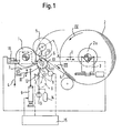
- Figure 1 shows a winding device with a winding roller 1 and a reel 2 a formed in the device and carrying drum 2 a on a winding carriage 3 which can be displaced in the direction of the arrow I. is rotatably mounted.
- the winding carriage 3 with the winding 2 carrying Drum 2a has already moved into the drum change position.
- the normal winding position, in which the winding 2 with the winding roller 1 in Contact is indicated by a dash-dotted line.
- an empty drum 5 is placed on the winding roller 1.
- the one according to the invention Separator arranged below the material web 4 and between the winding roller 1 and the empty reel 5 on the one hand and the winding 2 on the other hand.
- Separator includes a separation roller 6, on two swivel arms 7, of which only one is visible, over a motor 8 is rotatably driven.
- the swivel arms 7 with the Separating roller 6 are via lifting cylinder 9 between a dash-dotted line Rest position and that shown with solid lines Separation position pivotable according to arrow II.
- the separation roller 6 is on its outer circumference with knives 10 as separation elements and provided with blown air nozzles 11 in the area of the knives 10.
- the blown air nozzles 11 are from a pump 13 or a valve 12 Storage volume 14 can be charged with blown air.
- the control of the Valve 12 takes place via a control unit 15, which is also the lifting cylinder 9 and the motor 8 controls the rotation of the separation roller 6.
- the knives 10 are on the Separating roller 6 arranged along two spiral lines 18 and 19 by one common point 17 in the middle of the separating roller 6 starting in opposite directions run outwards.
- Each spiral line 18 and 19 includes the separation roller 6 exactly once.
- the spiral lines 18 and 19 can Separating roller 6 also include less or more than once, for example 1.5 or twice. This can reduce the inclination of the cutting edge to the web running direction III can be selected in the desired manner.
- the knives 10 are several along Partial spiral lines 20 arranged.
- the spiral lines 20 run alternately opposite to each other and connected to each other, so that a zigzag line is formed, which extends over a peripheral portion of the Separating roller 6 extends while the remaining circumference of the separating roller 6 is free of knives.
- the separating roller 6 has its Blown air pipes 21 on the outside, which are parallel to the knives 10, that is also extend spirally around the separation roller 6.
- the blow air pipes 21 are provided with blowing air nozzles 11 through which the blowing air exits can.
- the blown air nozzles 11 can thereby be close to the knives 10 be placed without the entire interior of the separating roller 6 with Compressed air would have to be filled. This accelerates the pressure build-up.
- the winding of the material web 4 onto the drum 2a takes place according to Arrow III, which indicates the direction of web travel, and arrow IV, which denotes the winding direction of the drum 2a.
- the winding roller 1 via a device 16 to the drum 2a or the ones located thereon Wrapped 2 pressed. If the drum 2a is almost fully wound, this is shown over the carriage 3 in the solid line Move the reel change position. Then an empty drum 5 applied to the winding roller 1 and the separating device according to the invention activated.
- the separating roller 6 is set in rotation so that its peripheral speed at least approximately the material running speed equivalent. Then the separating roller 6 from its rest position to her Separation position pivoted up and the valve 12 opened to compressed air to blow through the blowing air nozzles 11. Swiveling the separation roller up 6 is timed with their rotation so that the knife 10 on the roller 6 in the desired chronological order with the material web 4 engage.
- the control is carried out so that the Knife 10 in the middle of the separating roller 6, which at the arrow V indicated Direction of rotation of the roller 6 is the foremost knife, first comes into engagement with the material web 4. With further rotation of the roller 6, the remaining knives 10 arrive one after the other on the left and right of the center of the roller with the material web 4 in engagement. Since the material web 4 at the same time continues, there is an arrow-shaped cutting edge with in Arrow direction arrow III. By reverse order the knife 10 on the separation roller and start cutting with the An arrow-shaped cutting edge can be used with both outer knives arrow head pointing against the direction of web travel III.
- control can be designed in this way be that first the knife-free area of the separating roller 6 with the material web 4 engages. This simplifies control.
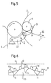
- FIG. 5 shows only a section of a winding device with winding roller 1 and winding 2 still in the winding position. At the same time is already here an empty drum 5 applied to the winding roller 1 is shown. Below the winding roller 1 and the empty reel 5 is the invention Separator arranged. A support beam 23 is on swivel arms 22 also hinged, which on its top with a Variety of knives 10 is provided. As can be seen in particular in FIG. 6 sees, the knives 10 are offset laterally and in height to each other the cutter bar 23 arranged. By swiveling the cutter bar up 23, the knives 10 arrive at different times with the material web 4 engaged. By simultaneously continuing to run the material web 4, this results in a cutting edge inclined to the web running direction III.
- the device is controlled in the same way as in the previous one variant described by the separation device according to the invention is swung up when changing the reel. Again, you can choose between Blower air nozzles 11 located on the blades 10 when pivoting upward Compressed air are applied to the formed new beginning of the path press the empty reel 5.
- a carrier 24 is attached, on which the knife 10 can be pivoted in this way are attached so that they are between a non-engaged position in which they are located below the material web 4 and are parallel to it extend, and an engagement position are pivotable, in which they run transversely to the material web 4 and with the swivel arms swung up 22 cross them.
- a camshaft 25 arranged below the knife 10, the cams 26, the knife 10 depending on the Raise or lower the rotational position of the camshaft 25.
- the camshaft 25 is driven in rotation so that the cams 26 are the knives 10 Swing up into the path of the material web 4.
- the cams 26 are distributed on the camshaft 25 so that the knife 10 with can be swiveled up with a time offset that the desired Form of the separating edge created.
- the knife in the middle the carrier 24 are pivoted up first, and then one after the other from the inside outwards Knife 10. Due to the simultaneous movement of the material web 4 this creates an arrow-shaped cut edge. Can accordingly other desired cut edges by swiveling up at different times the knife 10 are formed, for example a zigzag shape.
- the new beginning of the path formed is preferred pressed against the empty drum 5 by blowing air.
- blowing air are preferred provided on the carrier 24 between the knives 10 blowing air nozzles 11, which can be pressurized with compressed air.
- the knives can each have a smooth cutting edge or serrated be trained.
- the teeth can have an angle of approx. Have 30 ° and be about 40 mm high.
- the blowing air is introduced preferably via a compressed air reservoir, which in turn via a Pump can be filled. This allows the compressed air to quickly reach the desired level Size will be provided.
Landscapes
- Life Sciences & Earth Sciences (AREA)
- Forests & Forestry (AREA)
- Engineering & Computer Science (AREA)
- Mechanical Engineering (AREA)
- Replacement Of Web Rolls (AREA)
Claims (18)
- Procédé pour couper une bande de matière (4) roulante, en particulier une bande de papier, sur un dispositif d'enroulement lors du changement de tambour, dans lequel un dispositif de coupe (6, 23, 24) est déplacé dans la trajectoire de défilement de la bande, entre un cylindre d'enroulement (1) et un tambour vide (5) d'une part et un tambour (2a) portant une bobine (2) réalisée sur le dispositif d'autre part, la bande de matière (4) étant coupée successivement en plusieurs endroits sur la largeur de la bande de matière (4) par le dispositif de coupe (6, 23, 24) muni de plusieurs éléments de coupe (10) disposés côte à côte,
caractérisé en ce que
les points de coupure sont disposés, par rapport à la bande de matière (4), le long d'une ligne inclinée par rapport au sens de défilement (III) de la bande et traversant la largeur de la bande en zigzag, et
en ce que la nouvelle amorce de la bande de matière (4) créée par l'opération de coupe est déplacée en direction du tambour vide (5) à l'aide d'air de soufflage émis dans la région des éléments de coupe (10). - Dispositif pour couper une bande de matière (4) roulante, en particulier une bande de papier, sur un dispositif d'enroulement lors du changement de tambour, dans lequel un dispositif de coupe (6, 23, 24) peut être déplacé dans la trajectoire de défilement de la bande, entre un cylindre d'enroulement (1) et un tambour vide (5) d'une part et un tambour (2a) portant une bobine (2) réalisée sur le dispositif d'autre part, la bande de matière (4) étant coupée successivement en plusieurs endroits sur la largeur de la bande de matière (4) par le dispositif de coupe (6, 23, 24) muni de plusieurs éléments de coupe (10) disposés côte à côte,
caractérisé en ce que
les éléments de coupe (10) sont disposés sur un dispositif de coupe (6, 23, 24) s'étendant sensiblement sur la largeur de la bande de matière, lequel est mobile à partir d'une position de repos jusqu'à une position de coupe et retour, les éléments de coupe (10) étant disposés de sorte qu'ils génèrent, lors du déplacement du dispositif de coupe (6, 23, 24) jusqu'à la position de coupe, successivement plusieurs points de coupure qui sont disposés, par rapport à la bande de matière (4), le long d'une ligne inclinée par rapport au sens de défilement (III) de la bande et traversant la largeur de la bande en zigzag, et
en ce que des buses d'air de soufflage (11 ) sont prévues au niveau des éléments de coupe (10) pour aider à l'enroulement sur le tambour vide (5) de la nouvelle amorce de la bande de matière (4) créée. - Dispositif selon la revendication 2,
caractérisé en ce que
le dispositif de coupe a la forme d'un sommier (23) disposé sur le côté de la bande de matière (4) éloigné du tambour vide (5). - Dispositif selon la revendication 3,
caractérisé en ce que
le sommier (23) est monté de manière à pouvoir pivoter, de sorte que les éléments de coupe (10) agissent sur la bande de matière (4) les uns après les autres, en commençant par celui situé le plus en avant, vu dans le sens de défilement (III) de la bande. - Dispositif selon la revendication 2,
caractérisé en ce que
le dispositif de coupe a la forme d'un cylindre de coupe (6) pouvant être entraíné en rotation, sur la jupe duquel sont disposés plusieurs éléments de coupe (10) le long d'au moins une ligne en spirale (18, 19, 20). - Dispositif selon la revendication 5,
caractérisé en ce que
des moyens sont prévus, grâce auxquels la vitesse de rotation du cylindre de coupe (6) peut être adaptée, au moins approximativement, à la vitesse de défilement de la bande. - Dispositif selon la revendication 5 ou 6,
caractérisé en ce que
les buses d'air de soufflage (11) sont disposées chaque fois directement à côté d'un élément de coupe (10) et peuvent être alimentées en air de soufflage depuis l'intérieur du cylindre de coupe (6). - Dispositif selon la revendication 5, 6 ou 7,
caractérisé en ce que
au moins un tube d'air de soufflage (21) avec des buses d'air de soufflage (11) est prévu sur le côté extérieur de la jupe du cylindre de coupe (6). - Dispositif selon la revendication 8,
caractérisé en ce que
les tubes d'air de soufflage (21) sont disposés parallèlement aux éléments de coupe (10) le long d'une ligne en spirale. - Dispositif selon l'une des revendications 5 à 9,
caractérisé en ce que
les éléments de coupe (10) sont disposés le long d'une ligne en spirale traversant toute la largeur du cylindre de coupe (6). - Dispositif selon l'une des revendications 5 à 10,
caractérisé en ce que
des moyens de commande (15) sont prévus, grâce auxquels, successivement, le cylindre de coupe (6) peut être mis en rotation, les buses d'air de soufflage (11) peuvent être alimentées en air de soufflage et le cylindre de coupe (6) peut être amené à sa position de coupe, l'alimentation en air de soufflage des buses d'air de soufflage (11) s'effectuant de préférence immédiatement avant la plongée du cylindre de coupe (6) dans la bande de matière (4). - Dispositif selon la revendication 2,
caractérisé en ce que
le dispositif de coupe a la forme d'un support (24) s'étendant transversalement sur la largeur de la bande, sur lequel plusieurs éléments de coupe (10) sont disposés côte à côte, de manière répartie sur la largeur de la bande, et muni de moyens grâce auxquels les éléments de coupe (10) peuvent être amenés à agir sur la bande de matière (4) de manière décalée dans le temps les uns par rapport aux autres. - Dispositif selon la revendication 12,
caractérisé en ce que
plusieurs couteaux (10) sont disposés sur le support (24) de manière à pouvoir pivoter entre une position de repos, dans laquelle les couteaux (10) s'étendent, dans le sens de défilement (III) de la bande, à côté de la bande de matière (4), et une position de coupe, dans laquelle les couteaux (10) coupent la trajectoire de la bande. - Dispositif selon la revendication 13,
caractérisé en ce que
un arbre à cames (25) pouvant être entraíné en rotation et dont les cames (26) relèvent ou baissent les couteaux (10) en fonction de la position en rotation de l'arbre à cames (25), est monté en dessous des couteaux (10). - Dispositif selon la revendication 12, 13 ou 14,
caractérisé en ce que
les buses d'air de soufflage (11 ) sont disposées à chaque fois entre deux éléments de coupe (10). - Dispositif selon l'une des revendications 2 à 15,
caractérisé en ce que
des couteaux (10) sont prévus comme éléments de coupe. - Dispositif selon la revendication 16,
caractérisé en ce que
les couteaux (10) ont une lame droite. - Dispositif selon la revendication 16,
caractérisé en ce que
les couteaux (10) ont une lame dentelée.
Applications Claiming Priority (2)
| Application Number | Priority Date | Filing Date | Title |
|---|---|---|---|
| DE19848808A DE19848808A1 (de) | 1998-10-22 | 1998-10-22 | Verfahren zum Durchtrennen einer laufenden Materialbahn und Vorrichtung zur Durchführung des Verfahrens |
| DE19848808 | 1998-10-22 |
Publications (2)
| Publication Number | Publication Date |
|---|---|
| EP0997418A1 EP0997418A1 (fr) | 2000-05-03 |
| EP0997418B1 true EP0997418B1 (fr) | 2004-02-25 |
Family
ID=7885348
Family Applications (1)
| Application Number | Title | Priority Date | Filing Date |
|---|---|---|---|
| EP99114488A Expired - Lifetime EP0997418B1 (fr) | 1998-10-22 | 1999-07-23 | Méthode et dispositif pour couper une bande en déplacement |
Country Status (4)
| Country | Link |
|---|---|
| US (1) | US6464161B1 (fr) |
| EP (1) | EP0997418B1 (fr) |
| AT (1) | ATE260216T1 (fr) |
| DE (2) | DE19848808A1 (fr) |
Families Citing this family (6)
| Publication number | Priority date | Publication date | Assignee | Title |
|---|---|---|---|---|
| DE10343424A1 (de) * | 2003-09-19 | 2005-04-14 | Voith Paper Patent Gmbh | Wickelmaschine und Verfahren zum Heraustrennen eines Querstreifens aus einer Materialbahn in einer Wickelmaschine |
| DE10343453A1 (de) * | 2003-09-19 | 2005-04-14 | Voith Paper Patent Gmbh | Wickelmaschine |
| US8628641B2 (en) * | 2012-01-30 | 2014-01-14 | Paprima Industries Inc. | Web turn-up cutting apparatus and method |
| WO2018072018A1 (fr) | 2016-10-17 | 2018-04-26 | Paprima Industries Inc. | Procédé de retournement dans une machine à papier et de fabrication de papier |
| SE542363C2 (en) | 2017-02-22 | 2020-04-14 | Core Link Ab | Method and apparatus for removing wrapping from rolls |
| CN108994365B (zh) * | 2018-06-19 | 2023-11-14 | 凌云工业股份有限公司 | 一种用于条形冷弯成型产品件的侧向切断装置 |
Family Cites Families (18)
| Publication number | Priority date | Publication date | Assignee | Title |
|---|---|---|---|---|
| US2278029A (en) * | 1940-12-20 | 1942-03-31 | Russell E Walsh | Dispenser for sheet material |
| FR1238323A (fr) * | 1959-06-29 | 1960-08-12 | Etudes De Machines Speciales | Dispositif de rebobinage automatique |
| US3232739A (en) * | 1962-10-12 | 1966-02-01 | Sun Oil Co | Urea-extended polyurethane foam |
| US3323739A (en) * | 1965-06-08 | 1967-06-06 | Arthur T Deming | Paper mill knife and mounting therefor |
| DE2010072B2 (de) * | 1970-03-04 | 1972-10-12 | J.M. Voith Gmbh, 7920 Heidenheim | Tragtrommel-rollapparat zum aufwickeln von warenbahnen |
| DE2208968A1 (de) * | 1972-02-25 | 1973-09-06 | Joche Dipl Ing Schauenburg | Querschneideeinrichtung fuer kontinuierlich fortlaufende bahnen |
| DE2301193C2 (de) * | 1973-01-11 | 1985-09-19 | Maschinenfabrik Stahlkontor Weser Lenze KG, 3258 Aerzen | Vorrichtung zum Wickelrollenwechsel und zum Quertrennen von schnellaufenden Bahnen |
| US3857524A (en) * | 1973-10-05 | 1974-12-31 | Beloit Corp | Surface enveloper transfer winder |
| US3869095A (en) * | 1973-10-23 | 1975-03-04 | Beloit Corp | Three drum winder |
| US4458852A (en) * | 1981-06-05 | 1984-07-10 | American Hoechst Corporation | Web transfer apparatus |
| SE451833B (sv) * | 1982-03-15 | 1987-11-02 | Kahlman Innovation Ab | Forfarande och anordning for att kapa en rorlig bandformig materialbana samt tillfora en materialbaneende till en ny upplindningsrulle |
| DE3321213C2 (de) * | 1983-06-11 | 1986-12-11 | J.M. Voith Gmbh, 7920 Heidenheim | Wickelmaschine zum Aufwickeln einer endlosen Bahn |
| DE3515519A1 (de) * | 1985-04-30 | 1986-10-30 | J.M. Voith Gmbh, 7920 Heidenheim | Verfahren zum ueberfuehren einer bahn von einem fertigen wickel auf einen neuen wickelkern sowie tragtrommel-rollapparat zur durchfuehrung des verfahrens |
| DE4226418C2 (de) * | 1992-08-10 | 1995-08-17 | Agfa Gevaert Ag | Vorrichtung zum Aufwickeln bandförmiger fotografischer Schichtträger |
| DE4401804A1 (de) * | 1994-01-22 | 1994-06-23 | Voith Gmbh J M | Verfahren zum Aufwickeln einer laufenden Bahn sowie Wickelmaschine zum Durchführen des Verfahrens |
| WO1996011868A1 (fr) * | 1994-10-13 | 1996-04-25 | Valmet Corporation | Procede d'enroulage et dispositif d'echange associe |
| DE29508732U1 (de) * | 1995-05-26 | 1995-09-21 | Voith Sulzer Papiermaschinen GmbH, 89522 Heidenheim | Vorrichtung zum Perforieren einer laufenden Papierbahn |
| DE19710281A1 (de) * | 1997-03-13 | 1998-09-17 | Voith Sulzer Papiermasch Gmbh | Wickelmaschine |
-
1998
- 1998-10-22 DE DE19848808A patent/DE19848808A1/de not_active Withdrawn
-
1999
- 1999-07-23 EP EP99114488A patent/EP0997418B1/fr not_active Expired - Lifetime
- 1999-07-23 AT AT99114488T patent/ATE260216T1/de not_active IP Right Cessation
- 1999-07-23 DE DE59908631T patent/DE59908631D1/de not_active Expired - Fee Related
- 1999-10-15 US US09/419,295 patent/US6464161B1/en not_active Expired - Fee Related
Also Published As
| Publication number | Publication date |
|---|---|
| ATE260216T1 (de) | 2004-03-15 |
| US6464161B1 (en) | 2002-10-15 |
| DE19848808A1 (de) | 2000-04-27 |
| DE59908631D1 (de) | 2004-04-01 |
| EP0997418A1 (fr) | 2000-05-03 |
Similar Documents
| Publication | Publication Date | Title |
|---|---|---|
| DE3515519C2 (fr) | ||
| AT393260B (de) | Vorrichtung zum aufwickeln einer endlosen bahn, z. b. papier- oder kartonbahn, auf wickelwalzen | |
| DE69900919T2 (de) | Vorrichtung zum perforieren von bahnförmigen materialien mit mitteln zum verändern des abstandes zwischen nebeneinander angeordneten perforationslinien | |
| DE69821803T2 (de) | Wickelmaschine und verfahren zum wechseln einer rolle | |
| EP2803609B1 (fr) | Machine d'enroulement de matériaux en forme de bande | |
| DE69624075T2 (de) | Aufwickelmaschine | |
| EP2874790B1 (fr) | Dispositif de découpage et procédé de sectionnement transversal d'une bande de matière fibreuse en mouvement | |
| EP0744367A2 (fr) | Appareil pour produire une trace de perforation sur une bande en mouvement, par exemple une bande de papier | |
| EP0997418A1 (fr) | Méthode et dispositif pour couper une bande en déplacement | |
| DE69708653T2 (de) | Quertrennvorrichtung für eine wickelmaschine | |
| DE2522011A1 (de) | Einrichtung zum aufwickeln von bahnen aus papier, zellstoff o.dgl. | |
| EP1454858A1 (fr) | Enrouleuse | |
| DE4425662C1 (de) | Vorrichtung zum Quertrennen einer Papierbahn | |
| EP0327725B1 (fr) | Bobineuse avec cylindres porteurs pour enrouler une feuille continue, notamment une feuille continue en papier ou carton, aux mandrins | |
| DE4425201C2 (de) | Verfahren und Vorrichtung zum Trennen einer Kunststoffwarenbahn in einer Rollenschneid- und Wickelmaschine | |
| EP0734988B1 (fr) | Méthode et appareil pour mettre en mouvement des aiguilles de perforation | |
| DE3237314A1 (de) | Rotierende drahtschere | |
| EP1321406B1 (fr) | Dispositif pour enrouler une bande | |
| DE2243504C2 (de) | Vorrichtung zum fortlaufenden Aufwickeln einer Folienbahn auf Wickelhülsen | |
| DE4415316A1 (de) | Rollenwickelmaschine | |
| DE2414564C3 (de) | Vorrichtung zum Quertrennen von kontinuierlich ablaufenden, in Abständen zur Ausbildung von AbreiBschwächungsUnien quer perforierten Werkstoffbahnen | |
| EP1035053B1 (fr) | Méthode pour bobiner une bande de matériau et bobineuse pour réaliser cette méthode | |
| EP0739547B1 (fr) | Procede et dispositif d'enroulement de bobines pour moteurs ou generateurs electriques | |
| DE202010008015U1 (de) | Vorrichtung zum Wickeln einer Folienbahn | |
| EP1206982B1 (fr) | Cisaille rotative pour séparer les extrémités avants et arrières de matériau laminé continu |
Legal Events
| Date | Code | Title | Description |
|---|---|---|---|
| PUAI | Public reference made under article 153(3) epc to a published international application that has entered the european phase |
Free format text: ORIGINAL CODE: 0009012 |
|
| AK | Designated contracting states |
Kind code of ref document: A1 Designated state(s): AT DE FI SE |
|
| AX | Request for extension of the european patent |
Free format text: AL;LT;LV;MK;RO;SI |
|
| RAP1 | Party data changed (applicant data changed or rights of an application transferred) |
Owner name: VOITH PAPER PATENT GMBH |
|
| 17P | Request for examination filed |
Effective date: 20001103 |
|
| AKX | Designation fees paid |
Free format text: AT DE FI SE |
|
| 17Q | First examination report despatched |
Effective date: 20020621 |
|
| GRAP | Despatch of communication of intention to grant a patent |
Free format text: ORIGINAL CODE: EPIDOSNIGR1 |
|
| GRAS | Grant fee paid |
Free format text: ORIGINAL CODE: EPIDOSNIGR3 |
|
| GRAA | (expected) grant |
Free format text: ORIGINAL CODE: 0009210 |
|
| AK | Designated contracting states |
Kind code of ref document: B1 Designated state(s): AT DE FI SE |
|
| REF | Corresponds to: |
Ref document number: 59908631 Country of ref document: DE Date of ref document: 20040401 Kind code of ref document: P |
|
| REG | Reference to a national code |
Ref country code: SE Ref legal event code: TRGR |
|
| PLBE | No opposition filed within time limit |
Free format text: ORIGINAL CODE: 0009261 |
|
| STAA | Information on the status of an ep patent application or granted ep patent |
Free format text: STATUS: NO OPPOSITION FILED WITHIN TIME LIMIT |
|
| 26N | No opposition filed |
Effective date: 20041126 |
|
| PGFP | Annual fee paid to national office [announced via postgrant information from national office to epo] |
Ref country code: SE Payment date: 20070712 Year of fee payment: 9 |
|
| PGFP | Annual fee paid to national office [announced via postgrant information from national office to epo] |
Ref country code: DE Payment date: 20080722 Year of fee payment: 10 |
|
| PGFP | Annual fee paid to national office [announced via postgrant information from national office to epo] |
Ref country code: FI Payment date: 20080715 Year of fee payment: 10 Ref country code: AT Payment date: 20080715 Year of fee payment: 10 |
|
| EUG | Se: european patent has lapsed | ||
| PG25 | Lapsed in a contracting state [announced via postgrant information from national office to epo] |
Ref country code: FI Free format text: LAPSE BECAUSE OF NON-PAYMENT OF DUE FEES Effective date: 20090723 |
|
| PG25 | Lapsed in a contracting state [announced via postgrant information from national office to epo] |
Ref country code: DE Free format text: LAPSE BECAUSE OF NON-PAYMENT OF DUE FEES Effective date: 20100202 Ref country code: AT Free format text: LAPSE BECAUSE OF NON-PAYMENT OF DUE FEES Effective date: 20090723 |
|
| PG25 | Lapsed in a contracting state [announced via postgrant information from national office to epo] |
Ref country code: SE Free format text: LAPSE BECAUSE OF NON-PAYMENT OF DUE FEES Effective date: 20080724 |