EP0997420A2 - Vorrichtung zum Bilden und Abfördern von Bogenstapeln - Google Patents
Vorrichtung zum Bilden und Abfördern von Bogenstapeln Download PDFInfo
- Publication number
- EP0997420A2 EP0997420A2 EP99120599A EP99120599A EP0997420A2 EP 0997420 A2 EP0997420 A2 EP 0997420A2 EP 99120599 A EP99120599 A EP 99120599A EP 99120599 A EP99120599 A EP 99120599A EP 0997420 A2 EP0997420 A2 EP 0997420A2
- Authority
- EP
- European Patent Office
- Prior art keywords
- stack
- stops
- platform
- stacking
- sheet
- Prior art date
- Legal status (The legal status is an assumption and is not a legal conclusion. Google has not performed a legal analysis and makes no representation as to the accuracy of the status listed.)
- Granted
Links
Images




Classifications
-
- B—PERFORMING OPERATIONS; TRANSPORTING
- B65—CONVEYING; PACKING; STORING; HANDLING THIN OR FILAMENTARY MATERIAL
- B65H—HANDLING THIN OR FILAMENTARY MATERIAL, e.g. SHEETS, WEBS, CABLES
- B65H29/00—Delivering or advancing articles from machines; Advancing articles to or into piles
- B65H29/66—Advancing articles in overlapping streams
-
- B—PERFORMING OPERATIONS; TRANSPORTING
- B65—CONVEYING; PACKING; STORING; HANDLING THIN OR FILAMENTARY MATERIAL
- B65H—HANDLING THIN OR FILAMENTARY MATERIAL, e.g. SHEETS, WEBS, CABLES
- B65H31/00—Pile receivers
- B65H31/20—Pile receivers adjustable for different article sizes
-
- B—PERFORMING OPERATIONS; TRANSPORTING
- B65—CONVEYING; PACKING; STORING; HANDLING THIN OR FILAMENTARY MATERIAL
- B65H—HANDLING THIN OR FILAMENTARY MATERIAL, e.g. SHEETS, WEBS, CABLES
- B65H31/00—Pile receivers
- B65H31/30—Arrangements for removing completed piles
- B65H31/3036—Arrangements for removing completed piles by gripping the pile
- B65H31/3045—Arrangements for removing completed piles by gripping the pile on the outermost articles of the pile for clamping the pile
-
- B—PERFORMING OPERATIONS; TRANSPORTING
- B65—CONVEYING; PACKING; STORING; HANDLING THIN OR FILAMENTARY MATERIAL
- B65H—HANDLING THIN OR FILAMENTARY MATERIAL, e.g. SHEETS, WEBS, CABLES
- B65H31/00—Pile receivers
- B65H31/32—Auxiliary devices for receiving articles during removal of a completed pile
-
- B—PERFORMING OPERATIONS; TRANSPORTING
- B65—CONVEYING; PACKING; STORING; HANDLING THIN OR FILAMENTARY MATERIAL
- B65H—HANDLING THIN OR FILAMENTARY MATERIAL, e.g. SHEETS, WEBS, CABLES
- B65H2301/00—Handling processes for sheets or webs
- B65H2301/40—Type of handling process
- B65H2301/42—Piling, depiling, handling piles
- B65H2301/422—Handling piles, sets or stacks of articles
- B65H2301/4224—Gripping piles, sets or stacks of articles
- B65H2301/42242—Gripping piles, sets or stacks of articles by acting on the outermost articles of the pile for clamping the pile
-
- B—PERFORMING OPERATIONS; TRANSPORTING
- B65—CONVEYING; PACKING; STORING; HANDLING THIN OR FILAMENTARY MATERIAL
- B65H—HANDLING THIN OR FILAMENTARY MATERIAL, e.g. SHEETS, WEBS, CABLES
- B65H2405/00—Parts for holding the handled material
- B65H2405/50—Gripping means
- B65H2405/52—Gripping means reciprocating
-
- B—PERFORMING OPERATIONS; TRANSPORTING
- B65—CONVEYING; PACKING; STORING; HANDLING THIN OR FILAMENTARY MATERIAL
- B65H—HANDLING THIN OR FILAMENTARY MATERIAL, e.g. SHEETS, WEBS, CABLES
- B65H2511/00—Dimensions; Position; Numbers; Identification; Occurrences
- B65H2511/10—Size; Dimensions
- B65H2511/11—Length
-
- Y—GENERAL TAGGING OF NEW TECHNOLOGICAL DEVELOPMENTS; GENERAL TAGGING OF CROSS-SECTIONAL TECHNOLOGIES SPANNING OVER SEVERAL SECTIONS OF THE IPC; TECHNICAL SUBJECTS COVERED BY FORMER USPC CROSS-REFERENCE ART COLLECTIONS [XRACs] AND DIGESTS
- Y10—TECHNICAL SUBJECTS COVERED BY FORMER USPC
- Y10S—TECHNICAL SUBJECTS COVERED BY FORMER USPC CROSS-REFERENCE ART COLLECTIONS [XRACs] AND DIGESTS
- Y10S414/00—Material or article handling
- Y10S414/10—Associated with forming or dispersing groups of intersupporting articles, e.g. stacking patterns
- Y10S414/114—Adjust to handle articles or groups of different sizes
Definitions
- the invention relates to a device for forming and conveying sheet stacks in or out of a stacking tray, with a collection box, the front and rear Stacking stops is limited, their mutual distance on the format length the sheet stack is adjustable, as well as with a sheet feeding conveyor, which corresponds to a height-adjustable platform, which is in shape a separating rake in synchronism with the withdrawal movement of a stack removal device can be advanced into the stacking tray in the sheet transport direction.
- the invention has for its object measures to optimize all To meet the individual requirements of the work result.
- the rear stack stops are arranged adjustable along the sheet transport direction.
- the vertically defined platform and transport path can be moved up and down together. In this way, the same discharge height of the sheets fed in the shingled formation is ensured both when forming a new stack and when changing a stack.
- a further development that greatly facilitates a format change is that the rear stack tees, the platform and the transport path designed as a belt path are arranged on a common carriage that can be adjusted along the sheet transport direction. In this way, all components involved can be tracked with a single adjustment movement of the slide.
- a compact structural unit that facilitates both the perfect stack formation and the format adaptation is obtained in that the slide is arranged in a longitudinally displaceable manner on a slide carrier that can be moved vertically relative to the collecting box.
- the platform can be displaced relative to the slide with a shortened or lengthened longitudinal stroke adapted to the distance between the rear and front stacking stops.
- An additional simplification and simplification of the landscape format setting is achieved according to a further development in that the collection box has an exchangeable bottom bar equipped with support rakes, which is provided with lateral stack stops which are adjustable and lockable in transverse guides.
- the advantage achieved by the invention is that the format setting of the rear stacking stops means that the stack removal device, which is arranged downstream on the opposite side between the stacking tray and at the shortest possible distance, can always carry out the shortest possible longitudinal stroke, which ensures optimal conveying capacity.
- the economy is further improved by the format-dependent presettable side stacking stops on completely ready, quickly exchangeable floor platforms of the collection box. The time required for a changeover is minimized by means of all the sheet guide and stacking components that can be adjusted depending on the format with a single slide movement.
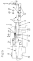
- the device has a stacking tray 1 for collecting paper sheets 2 to form sheet stacks 3, which is divided into numerous collecting boxes 4, one behind the other perpendicular to the plane of the drawing, and which - based on the sheet or stack transport direction (arrow 6) - upstream one Transport conveyor 7 designed as a belt conveyor for paper sheets 2 fed in a shingled formation and downstream are associated with a stack removal device 8 designed as a gripper 5 with subsequent transverse transport means 9, which have lifting and lowering transport belts 11 with integrated air table segments 12.
- the stacking tray 1 is delimited by front stacking stops 13 and rear stacking stops 14, of which the former can be pivoted from a stop position according to FIG. 1b into an inoperative position according to FIG. 1a.
- the rear stacking stops 14 are fastened to a slide 16 which can be displaced in the direction of the double arrow 15 and on which the transport track 7 and a platform 17 designed as a separating rake are also displaceably displaceable in the longitudinal direction relative to the slide 16 with a variable stroke.
- the discharge end 18 of the transport path 7 is at a defined distance from the platform 17.
- the carriage 16 is in turn slidably arranged on a carriage support 21 which can be moved vertically in the direction of the double arrow 19.
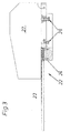
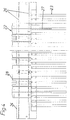
- the collecting box 4 is equipped with a floor platform 22, which according to FIGS. 3 and 4 is equipped with numerous parallel support rakes 23, which are fastened to a floor rail 24, which also carries lateral stacking stops 27, which can be set and fixed depending on the format, with corresponding spacers 28 are inserted.
- the floor platforms 22 are kept ready as a complete exchange group with format-dependent preset side stacking stops 27.
- FIGS. 1a to 1d The operation of the device according to FIGS. 1a to 1d is as follows: According to FIG. 1a, a sheet stack 3 formed from a defined number of accumulated paper sheets 2 is gripped by the gripper 5 of the stack removal device 8 after the front stack stop 13 has been swung away and in the conveying direction 6 from the Stacking tray 1 is transferred to the transverse transport means 9, which optionally transport the sheet stack according to FIG. 1d in the directions perpendicular to the plane of the drawing, identified by the arrow symbols 29 and 31.
- the platform 17 consisting of rows of bars follows the back of the sheet stack 3 up to the stop against the stack stop 13 moved back into the stop position, the permanently scaled paper sheets 2 being simultaneously transferred to the platform 17 without interruption.
- the slide carrier 21 By moving the slide carrier 21 in the direction of the double arrow 19 according to FIG. 1c, the platform 17 is lowered to the base platform 22 of the stacking tray 1 or possibly below its level and, according to FIG. 1d, is withdrawn from the stacking tray 1 into the starting position, so that the new sheet stack 3 is taken over by the floor platform 22. Due to the subsequent upward movement of the carriage carrier 21 in the direction of the double arrow 19, the discharge end 18 of the transport path 7 is raised to the extent that the stack height of the sheet stack 3 increases, so that a constant discharge height for the paper sheets 2 is always guaranteed.
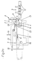
- the rear stack stop 14 and the shedding end 18 of the transport path 7 and the platform 17 are moved towards the front stack stop 13 in a distance-reducing manner by inward displacement of the slide 16 in the direction of the double arrow 15.
- the landscape format is adjusted perpendicular to the plane of the drawing by replacing the floor platform 22 with a replacement floor platform which is provided and is equipped with correspondingly preset lateral stacking stops 27.
- the longitudinal stroke of the platform 17 is in accordance with the longitudinal shortening of the stacking tray 1 adapted during the longitudinal stroke of the stack removal device 8 due to the always constant stroke limitation on the front stack stop 13 in remains essentially unchanged, due to the format adjustment described the smaller sheet format is even shortened.
Landscapes
- Engineering & Computer Science (AREA)
- Mechanical Engineering (AREA)
- Pile Receivers (AREA)
- Forming Counted Batches (AREA)
- Electrical Discharge Machining, Electrochemical Machining, And Combined Machining (AREA)
- Separation, Sorting, Adjustment, Or Bending Of Sheets To Be Conveyed (AREA)
- Battery Mounting, Suspending (AREA)
Abstract
Description
Um im Zuge der Bogenansammlung bei der Stapelbildung stets gleiche Abwurfbedingungen zwischen der Transportbahn und der Stapelablage zu gewährleisten ist außerdem vorgesehen, daß die vertikal definiert zueinander beabstandete Plattform und Transportbahn gemeinsam auf- und abbewegbar sind. Auf diese Weise ist sowohl bei der Stapelbildung eines neuen Stapels als auch beim Stapelwechsel eine immer gleiche Abwurfhöhe der in geschuppter Formation zugeführten Bogen sichergestellt.
Eine einen Formatwechsel erheblich erleichternde Weiterbildung besteht darin, daß die hinteren Stapelabschläge, die Plattform und die als Bänderbahn ausgebildete Transportbahn an einem gemeinsamen, längs der Bogentransportrichtung verstellbaren Schlitten angeordnet sind. Auf diese Weise können mit einer einzigen Einstellbewegung des Schlittens alle beteiligten Komponenten nachgeführt werden.
Um auch die Bewegung der Plattform exakt an die jeweilige Formateinstellung anpassen zu können, wird außerdem vorgeschlagen, daß die Plattform relativ zum Schlitten mit einem entsprechend dem Abstand zwischen hinteren und vorderen Stapelanschlägen angepaßten verkürzten oder verlängerten Längshub verschiebbar ist.
Eine zusätzliche Vereinfachung und Erleichterung der Querformat-Einstellung wird gemäß einer Weiterbildung dadurch erreicht, daß die Sammelbox eine mit Stützrechen bestückte austauschbare Bodenleiste aufweist, welche mit in Querführungen verstellbaren und arretierbaren seitlichen Stapelanschlägen versehen ist.
Zudem wird durch die formatabhängig voreinstellbaren seitlichen Stapelanschläge an komplett bereitstehenden, schnell auswechselbaren Bodenplattformen der Sammelbox die Wirtschaftlichkeit weiter verbessert.
Durch alle mit einer einzigen Schlittenbewegung formatabhängig einstellbaren Bogenführungs- und Stapelbildungskomponenten wird der Zeitaufwand für eine Umrüstung minimiert.
- Figuren 1a - 1d
- den Aufbau und unterschiedliche Arbeitsstellungen einer Vorrichtung zum Aufbau und zur Abförderung von Papierstapeln,
- Figuren 2a und 2b
- unterschiedliche Arbeitsstellungen der Vorrichtung mit einer alternativen Formateinstellung,
- Figur 3
- eine Seitenansicht eines Teils der Bodenplattform einer Sammelbox und
- Figur 4
- eine Draufsicht auf die Bodenplattform gemäß Figur 3.
Die Stapelablage 1 ist von vorderen Stapelanschlägen 13 und hinteren Stapelanschlägen 14 begrenzt, von denen erstere aus einer Anschlagstellung gemäß Figur 1b in eine Außerbetriebsstellung gemäß Figur 1a verschwenkbar sind.
Die hinteren Stapelanschläge 14 sind an einem in Richtung des Doppelpfeils 15 verschiebbaren Schlitten 16 befestigt, an welchem zusätzlich auch die Transportbahn 7 sowie in Längsrichtung relativ zum Schlitten 16 mit veränderbarem Hub verschiebbar eine als Trennrechen ausgebildete Plattform 17 angeordnet sind.
Der Schlitten 16 ist wiederum verschiebbar an einem in Richtung des Doppelpfeils 19 höhenverfahrbaren Schlittenträger 21 angeordnet.
Die Sammelbox 4 ist mit einer Bodenplattform 22 ausgestattet, welche gemäß den Figuren 3 und 4 mit zahlreichen parallelen Stützrechen 23 bestückt ist, die an einer Bodenleiste 24 befestigt sind, welche außerdem in Querführungen 26 formatabhängig einstellbare und festsetzbare seitliche Stapelanschläge 27 trägt, wozu entsprechende Abstandshalter 28 eingefügt sind.
Die Bodenplattformen 22 werden mit formatabhängig voreingestellten seitlichen Stapelanschlägen 27 als komplette Austauschgruppe bereitgehalten.
Synchron mit der Überführungsbewegung der Stapelentnahmevorrichtung 8 folgt die aus Stabreihen bestehende Plattform 17 der Rückseite des Bogenstapels 3 bis zum Anschlag an den wieder in die Anschlagstellung zurückbewegten Stapelanschlag 13, wobei die permanent geschuppt zugeführten Papierbogen 2 gleichzeitig ohne Unterbrechung auf die Plattform 17 überführt werden.
Durch Herunterfahren des Schlittenträgers 21 in Richtung des Doppelpfeils 19 gemäß Figur 1c wird die Plattform 17 bis auf die Bodenplattform 22 der Stapelablage 1 oder gegebenenfalls bis unter deren Niveau abgesenkt und gemäß Figur 1d aus der Stapelablage 1 in die Ausgangsstellung zurückgezogen, so daß der neue Bogenstapel 3 von der Bodenplattform 22 übernommen wird.
Durch die anschließende Aufwärtsbewegung des Schlittenträgers 21 in Richtung des Doppelpfeils 19 wird das Abwurfende 18 der Transportbahn 7 in dem Maße angehoben wie die Stapelhöhe des Bogenstapels 3 zunimmt, so daß immer eine gleichbleibende Abwurfhöhe für die Papierbogen 2 gewährleistet bleibt.
Eine Anpassung des Querformats senkrecht zur Zeichenebene erfolgt durch Austausch der Bodenplattform 22 gegen eine bereitstehende, mit entsprechend voreingestellten seitlichen Stapelanschlägen 27 bestückte Ersatz-Bodenplattform.
Claims (6)
- Vorrichtung zum Bilden und Abfördern von Bogenstapeln in bzw. aus einer Stapelablage, mit einer Sammelbox, die von vorderen und hinteren Stapelanschlägen begrenzt ist, deren gegenseitiger Abstand auf die Formatlänge der Bogenstapel einstellbar ist, sowie mit einer Bogen zuführenden Transportbahn, die mit einer höhenverfahrbaren Plattform korrespondiert, welche in Form eines Trennrechens synchron mit der Abzugsbewegung einer Stapelentnahmevorrichtung in Bogentransportrichtung in die Stapelablage vorbewegbar ist, dadurch gekennzeichnet, daß die hinteren Stapelanschläge (14) längs der Bogentransportrichtung (Pfeil 6) verstellbar angeordnet sind.
- Vorrichtung nach Anspruch 1, dadurch gekennzeichnet, daß die vertikal definiert zueinander beabstandete Plattform (17) und Transportbahn (7) gemeinsam auf- und abbewegbar sind.
- Vorrichtung nach Anspruch 1 oder 2, dadurch gekennzeichnet, daß die hinteren Stapelanschläge (14), die Plattform (17) und die als Bänderbahn ausgebildete Transportbahn (7) an einem gemeinsamen, längs der Bogentransportrichtung (6) verstellbaren Schlitten (16) angeordnet sind.
- Vorrichtung nach Anspruch 3, dadurch gekennzeichnet, daß der Schlitten (16) längsverfahrbar an einem relativ zur Sammelbox (4) höhenverfahrbaren Schlittenträger (21) angeordnet ist.
- Vorrichtung nach Anspruch 3, dadurch gekennzeichnet, daß die Plattform (17) relativ zum Schlitten (16) mit einem entsprechend dem Abstand zwischen hinteren und vorderen Stapelanschlägen (14 bzw. 13) angepaßten verkürzten oder verlängerten Längshub verschiebbar ist.
- Vorrichtung nach einem der Ansprüche 1 bis 5, dadurch gekennzeichnet, daß die Sammelbox (4) eine mit Stützrechen (23) bestückte austauschbare Bodenleiste (24) aufweist, welche mit in Querführungen (26) verstellbaren und arretierbaren seitlichen Stapelanschlägen (27) versehen ist.
Applications Claiming Priority (2)
| Application Number | Priority Date | Filing Date | Title |
|---|---|---|---|
| DE19849859 | 1998-10-29 | ||
| DE19849859A DE19849859A1 (de) | 1998-10-29 | 1998-10-29 | Vorrichtung zum Bilden und Abfördern von Bogenstapeln |
Publications (3)
| Publication Number | Publication Date |
|---|---|
| EP0997420A2 true EP0997420A2 (de) | 2000-05-03 |
| EP0997420A3 EP0997420A3 (de) | 2001-05-16 |
| EP0997420B1 EP0997420B1 (de) | 2004-04-14 |
Family
ID=7886036
Family Applications (1)
| Application Number | Title | Priority Date | Filing Date |
|---|---|---|---|
| EP99120599A Expired - Lifetime EP0997420B1 (de) | 1998-10-29 | 1999-10-16 | Vorrichtung zum Bilden und Abfördern von Bogenstapeln |
Country Status (7)
| Country | Link |
|---|---|
| US (1) | US6527501B2 (de) |
| EP (1) | EP0997420B1 (de) |
| JP (1) | JP2000136062A (de) |
| AT (1) | ATE264262T1 (de) |
| DE (2) | DE19849859A1 (de) |
| ES (1) | ES2216404T3 (de) |
| PT (1) | PT997420E (de) |
Cited By (3)
| Publication number | Priority date | Publication date | Assignee | Title |
|---|---|---|---|---|
| EP2505536A3 (de) * | 2011-03-31 | 2013-03-06 | Kugler-Womako GmbH | Stapelbildungsvorrichtung |
| EP3216709A1 (de) * | 2016-03-11 | 2017-09-13 | INDAG Gesellschaft für Industriebedarf mbH & Co. Betriebs KG | Schachtsystem umfassend mehrere parallel nebeneinander angeordnete aufnahmeschächte zum aufnehmen von folienbeuteln |
| DE102016214970A1 (de) * | 2016-08-11 | 2018-02-15 | Koenig & Bauer Ag | Auslagevorrichtung mit zumindest einer Abgabestation und ein Verfahren zur Auslage von Bedruckstoffbogen in einer Auslagevorrichtung |
Families Citing this family (15)
| Publication number | Priority date | Publication date | Assignee | Title |
|---|---|---|---|---|
| DE10208309A1 (de) | 2002-02-27 | 2003-09-04 | Will E C H Gmbh & Co | Vorrichtung zum Bilden und Abfördern von Bogenstapeln mit einem Trennband |
| DE10244698B4 (de) * | 2002-09-24 | 2011-02-03 | Manroland Ag | Non-Stop-Einrichtung für einen Bogenausleger |
| JP4160362B2 (ja) * | 2002-10-30 | 2008-10-01 | グローリー株式会社 | 集積装置および循環式紙幣入出金機 |
| WO2004060777A2 (en) * | 2002-12-31 | 2004-07-22 | Shuttleworth, Inc. | Compression passing roller |
| DE102004056018A1 (de) * | 2004-11-16 | 2006-05-18 | Bielomatik Leuze Gmbh + Co.Kg | Fördereinrichtung für durch Blattlagen gebildete Stapel |
| JP2006327744A (ja) * | 2005-05-25 | 2006-12-07 | Kida Tekkosho:Kk | サンプリング紙取出し装置 |
| DE102006028381A1 (de) * | 2006-06-19 | 2007-12-20 | E.C.H. Will Gmbh | Verfahren und Vorrichtung zur Bildung von Stapeln von Flachteilen |
| ATE551285T1 (de) * | 2008-09-17 | 2012-04-15 | Bielomatik Leuze Gmbh & Co Kg | Sammel- und transportvorrichtung für durch blattlagen gebildete stapel |
| EP2520526B1 (de) * | 2010-05-12 | 2016-04-13 | Macarbox, S.L.U. | Maschine zum stapeln flacher elemente |
| SE536000C2 (sv) * | 2011-09-01 | 2013-03-26 | Plockmatic Int Ab | Maskin för framställning av häften |
| CH705846A1 (de) * | 2011-12-07 | 2013-06-14 | Ferag Ag | Einrichtung und Verfahren zum Zusammenstellen von flächigen Produkten, insbesondere von Druckereiprodukten. |
| JP2014164349A (ja) * | 2013-02-21 | 2014-09-08 | Glory Ltd | 紙葉類集積装置 |
| CN107250011B (zh) * | 2014-12-18 | 2019-05-10 | 鲍勃斯脱格伦兴股份公司 | 用于将扁平元件堆提供给加工装置的供料系统 |
| JP6440288B1 (ja) * | 2018-08-08 | 2018-12-19 | ホリゾン・インターナショナル株式会社 | 三方断裁機 |
| US11479433B2 (en) * | 2018-10-30 | 2022-10-25 | Ricoh Company, Ltd. | Sheet conveying device and image forming apparatus incorporating the sheet conveying device |
Family Cites Families (13)
| Publication number | Priority date | Publication date | Assignee | Title |
|---|---|---|---|---|
| DE1071101B (de) * | 1959-12-17 | Minmetal A.G., Zürich (Schweiz) | Bogenförderanlage mit Vorrichtung zum Bilden von Bogenlagen bestimmter Stückzahl | |
| US2466544A (en) * | 1946-10-12 | 1949-04-05 | Bostitch Inc | Apparatus for stacking and conveying objects |
| US3191927A (en) * | 1963-06-20 | 1965-06-29 | Crown Zellerbach Corp | Stacking apparatus and method |
| BE772622A (fr) * | 1971-09-15 | 1972-01-17 | Printex | Dispositif d'empilage, |
| DE2508745C2 (de) * | 1975-02-28 | 1985-07-18 | Womako Maschinenkonstruktionen GmbH, 7440 Nürtingen | Vorrichtung zum Aufstauen vereinzelt mittels einer Transportvorrichtung zugeförderter Papierbögen zu Stapeln und zum Weitertransportieren dieser Stapel |
| DE3046107C2 (de) * | 1980-12-06 | 1982-11-18 | Bielomatik Leuze Gmbh + Co, 7442 Neuffen | Vorrichtung zum Ablegen von Bogen zu einem Stapel |
| DE3220813C2 (de) * | 1982-06-03 | 1985-02-07 | Bielomatik Leuze Gmbh + Co, 7442 Neuffen | Vorrichtung zum Stapeln von Bogen |
| DE3601294A1 (de) | 1986-01-17 | 1987-07-23 | Waertsilae Strecker Gmbh | Bogenstapelvorrichtung |
| US5000657A (en) * | 1989-01-23 | 1991-03-19 | Gunther International, Ltd. | Two-way conveyor |
| US5178379A (en) * | 1991-07-23 | 1993-01-12 | Pitney Bowes Inc. | Sheet collator with alignment apparatus |
| US5484255A (en) * | 1994-04-18 | 1996-01-16 | Pitney Bowes Inc. | High capacity, high speed document accumulator |
| DE19612293C2 (de) * | 1996-03-28 | 1998-10-08 | Heidelberger Druckmasch Ag | Einrichtung zur automatischen Formateinstellung im Ausleger einer Rotationsdruckmaschine |
| US5980196A (en) * | 1998-05-13 | 1999-11-09 | Thermoguard Equipment, Inc. | Counter-ejector and box feed machine |
-
1998
- 1998-10-29 DE DE19849859A patent/DE19849859A1/de not_active Withdrawn
-
1999
- 1999-10-16 ES ES99120599T patent/ES2216404T3/es not_active Expired - Lifetime
- 1999-10-16 AT AT99120599T patent/ATE264262T1/de not_active IP Right Cessation
- 1999-10-16 DE DE59909156T patent/DE59909156D1/de not_active Expired - Fee Related
- 1999-10-16 EP EP99120599A patent/EP0997420B1/de not_active Expired - Lifetime
- 1999-10-16 PT PT99120599T patent/PT997420E/pt unknown
- 1999-10-26 JP JP11304574A patent/JP2000136062A/ja not_active Withdrawn
- 1999-10-28 US US09/428,643 patent/US6527501B2/en not_active Expired - Fee Related
Cited By (4)
| Publication number | Priority date | Publication date | Assignee | Title |
|---|---|---|---|---|
| EP2505536A3 (de) * | 2011-03-31 | 2013-03-06 | Kugler-Womako GmbH | Stapelbildungsvorrichtung |
| EP3216709A1 (de) * | 2016-03-11 | 2017-09-13 | INDAG Gesellschaft für Industriebedarf mbH & Co. Betriebs KG | Schachtsystem umfassend mehrere parallel nebeneinander angeordnete aufnahmeschächte zum aufnehmen von folienbeuteln |
| US10427817B2 (en) | 2016-03-11 | 2019-10-01 | Indag Pouch Partners Gmbh | Shaft system comprising a plurality of receiving shafts arranged in parallel side by side for receiving foil bags |
| DE102016214970A1 (de) * | 2016-08-11 | 2018-02-15 | Koenig & Bauer Ag | Auslagevorrichtung mit zumindest einer Abgabestation und ein Verfahren zur Auslage von Bedruckstoffbogen in einer Auslagevorrichtung |
Also Published As
| Publication number | Publication date |
|---|---|
| US6527501B2 (en) | 2003-03-04 |
| JP2000136062A (ja) | 2000-05-16 |
| PT997420E (pt) | 2004-08-31 |
| EP0997420A3 (de) | 2001-05-16 |
| US20020081187A1 (en) | 2002-06-27 |
| ATE264262T1 (de) | 2004-04-15 |
| EP0997420B1 (de) | 2004-04-14 |
| ES2216404T3 (es) | 2004-10-16 |
| DE59909156D1 (de) | 2004-05-19 |
| DE19849859A1 (de) | 2000-05-04 |
Similar Documents
| Publication | Publication Date | Title |
|---|---|---|
| EP0997420B1 (de) | Vorrichtung zum Bilden und Abfördern von Bogenstapeln | |
| EP0494404B1 (de) | Platterzuführvorrichtung für Plattenaufteilsägen | |
| DE69500305T2 (de) | Stapel-, Trennungs- und Abführungsstation für blattförmiges Gut, das von einer Verarbeitungsmaschine abgegeben wird | |
| DE3616470A1 (de) | Verfahren und vorrichtung zum ablegen kontinuierlich zu einer stapelstelle gefoerderter bogen | |
| EP0487837A1 (de) | Palettiermaschine | |
| EP0623542A1 (de) | Einrichtung zur Bildung eines sich senkrecht zu den stehend aneinandergereihten Druckbogen erstreckenden Stapels | |
| EP0359920B1 (de) | Vorrichtung zum automatischen Stapeln von plattenartigen flachen Elementen | |
| EP0718231A2 (de) | Vorrichtung zum Stapeln von Bögen, insbesondere von geschuppt zugeförderten Papier- oder Kartonbögen | |
| EP0392139A2 (de) | Vorrichtung zum riesweisen Ablegen von Bögen, insbesondere Papierbögen, auf einen Stapel | |
| EP1405809B1 (de) | Einrichtung zur Herstellung von Stapelpaketen | |
| DE3306575C2 (de) | ||
| EP0243944B1 (de) | Vorrichtung zur Herstellung gebündelter Stangen aus gefalzten Papierbogen | |
| DE112017004286T5 (de) | Pressvorrichtung und verfahren zur steuerung der pressvorrichtung | |
| EP2505536B1 (de) | Stapelbildungsvorrichtung | |
| WO1988000921A1 (fr) | Dispositif pour empiler des produits imprimes plies | |
| DE102005002532A1 (de) | Vorrichtung und Verfahren zum automatisierten und zeitgleichen Bereitstellen und Wechseln von mindestens zwei Rollen aus Papierbahnen oder dergleichen für einen nachgeordneten Formatschneider | |
| EP1251093B1 (de) | Vorrichtung zum Abstapeln von Faltschachtelschläuchen | |
| EP1447362B1 (de) | Vorrichtung zum Stapeln eines einlaufenden Bogenstroms | |
| EP1199275B1 (de) | Einrichtung zur Bildung eines Stapels aneinandergereihter Druckbogen | |
| DE102008024599A1 (de) | Vorrichtung zur Bildung von Stapelpaketen | |
| DE19517295A1 (de) | Einrichtung zum Beschicken von Plattenaufteilanlagen mit plattenförmigen Werkstücken | |
| EP0019036A1 (de) | Vorrichtung zum Stapeln von quaderförmigen Produkten, insbesondere von quaderförmigen Druckerzeugnissen, Zeitschriften oder dergleichen | |
| DE2753048C2 (de) | Verfahren und Vorrichtung zur Herstellung einer gebündelten Stange aus Druckbogen | |
| EP1117609A1 (de) | Vorrichtung zum stapeln von bögen | |
| EP1340705A2 (de) | Vorrichtung zum Bilden und Abfördern von Bogenstapeln mit einem Trennband |
Legal Events
| Date | Code | Title | Description |
|---|---|---|---|
| PUAI | Public reference made under article 153(3) epc to a published international application that has entered the european phase |
Free format text: ORIGINAL CODE: 0009012 |
|
| AK | Designated contracting states |
Kind code of ref document: A2 Designated state(s): AT BE CH CY DE DK ES FI FR GB GR IE IT LI LU MC NL PT SE |
|
| AX | Request for extension of the european patent |
Free format text: AL;LT;LV;MK;RO;SI |
|
| PUAL | Search report despatched |
Free format text: ORIGINAL CODE: 0009013 |
|
| RIC1 | Information provided on ipc code assigned before grant |
Free format text: 7B 65H 31/20 A, 7B 65H 31/32 B, 7B 65H 31/30 B |
|
| AK | Designated contracting states |
Kind code of ref document: A3 Designated state(s): AT BE CH CY DE DK ES FI FR GB GR IE IT LI LU MC NL PT SE |
|
| AX | Request for extension of the european patent |
Free format text: AL;LT;LV;MK;RO;SI |
|
| 17P | Request for examination filed |
Effective date: 20011102 |
|
| 17Q | First examination report despatched |
Effective date: 20020102 |
|
| AKX | Designation fees paid |
Free format text: AT BE CH CY DE DK ES FI FR GB GR IE IT LI LU MC NL PT SE |
|
| GRAP | Despatch of communication of intention to grant a patent |
Free format text: ORIGINAL CODE: EPIDOSNIGR1 |
|
| GRAS | Grant fee paid |
Free format text: ORIGINAL CODE: EPIDOSNIGR3 |
|
| GRAA | (expected) grant |
Free format text: ORIGINAL CODE: 0009210 |
|
| AK | Designated contracting states |
Kind code of ref document: B1 Designated state(s): AT BE CH CY DE DK ES FI FR GB GR IE IT LI LU MC NL PT SE |
|
| PG25 | Lapsed in a contracting state [announced via postgrant information from national office to epo] |
Ref country code: NL Free format text: LAPSE BECAUSE OF FAILURE TO SUBMIT A TRANSLATION OF THE DESCRIPTION OR TO PAY THE FEE WITHIN THE PRESCRIBED TIME-LIMIT Effective date: 20040414 Ref country code: IE Free format text: LAPSE BECAUSE OF FAILURE TO SUBMIT A TRANSLATION OF THE DESCRIPTION OR TO PAY THE FEE WITHIN THE PRESCRIBED TIME-LIMIT Effective date: 20040414 Ref country code: CY Free format text: LAPSE BECAUSE OF FAILURE TO SUBMIT A TRANSLATION OF THE DESCRIPTION OR TO PAY THE FEE WITHIN THE PRESCRIBED TIME-LIMIT Effective date: 20040414 |
|
| REG | Reference to a national code |
Ref country code: GB Ref legal event code: FG4D Free format text: NOT ENGLISH |
|
| REG | Reference to a national code |
Ref country code: CH Ref legal event code: EP |
|
| REF | Corresponds to: |
Ref document number: 59909156 Country of ref document: DE Date of ref document: 20040519 Kind code of ref document: P |
|
| REG | Reference to a national code |
Ref country code: IE Ref legal event code: FG4D Free format text: GERMAN |
|
| PG25 | Lapsed in a contracting state [announced via postgrant information from national office to epo] |
Ref country code: SE Free format text: LAPSE BECAUSE OF FAILURE TO SUBMIT A TRANSLATION OF THE DESCRIPTION OR TO PAY THE FEE WITHIN THE PRESCRIBED TIME-LIMIT Effective date: 20040714 Ref country code: GR Free format text: LAPSE BECAUSE OF FAILURE TO SUBMIT A TRANSLATION OF THE DESCRIPTION OR TO PAY THE FEE WITHIN THE PRESCRIBED TIME-LIMIT Effective date: 20040714 Ref country code: DK Free format text: LAPSE BECAUSE OF FAILURE TO SUBMIT A TRANSLATION OF THE DESCRIPTION OR TO PAY THE FEE WITHIN THE PRESCRIBED TIME-LIMIT Effective date: 20040714 |
|
| GBT | Gb: translation of ep patent filed (gb section 77(6)(a)/1977) |
Effective date: 20040706 |
|
| PGFP | Annual fee paid to national office [announced via postgrant information from national office to epo] |
Ref country code: ES Payment date: 20040817 Year of fee payment: 6 |
|
| REG | Reference to a national code |
Ref country code: PT Ref legal event code: SC4A Free format text: AVAILABILITY OF NATIONAL TRANSLATION Effective date: 20040625 |
|
| PGFP | Annual fee paid to national office [announced via postgrant information from national office to epo] |
Ref country code: GB Payment date: 20040917 Year of fee payment: 6 |
|
| PGFP | Annual fee paid to national office [announced via postgrant information from national office to epo] |
Ref country code: PT Payment date: 20040924 Year of fee payment: 6 |
|
| NLV1 | Nl: lapsed or annulled due to failure to fulfill the requirements of art. 29p and 29m of the patents act | ||
| PG25 | Lapsed in a contracting state [announced via postgrant information from national office to epo] |
Ref country code: LU Free format text: LAPSE BECAUSE OF NON-PAYMENT OF DUE FEES Effective date: 20041016 Ref country code: AT Free format text: LAPSE BECAUSE OF NON-PAYMENT OF DUE FEES Effective date: 20041016 |
|
| REG | Reference to a national code |
Ref country code: ES Ref legal event code: FG2A Ref document number: 2216404 Country of ref document: ES Kind code of ref document: T3 |
|
| PGFP | Annual fee paid to national office [announced via postgrant information from national office to epo] |
Ref country code: FR Payment date: 20041020 Year of fee payment: 6 |
|
| PGFP | Annual fee paid to national office [announced via postgrant information from national office to epo] |
Ref country code: FI Payment date: 20041021 Year of fee payment: 6 |
|
| PG25 | Lapsed in a contracting state [announced via postgrant information from national office to epo] |
Ref country code: MC Free format text: LAPSE BECAUSE OF NON-PAYMENT OF DUE FEES Effective date: 20041031 Ref country code: LI Free format text: LAPSE BECAUSE OF NON-PAYMENT OF DUE FEES Effective date: 20041031 Ref country code: CH Free format text: LAPSE BECAUSE OF NON-PAYMENT OF DUE FEES Effective date: 20041031 Ref country code: BE Free format text: LAPSE BECAUSE OF NON-PAYMENT OF DUE FEES Effective date: 20041031 |
|
| PGFP | Annual fee paid to national office [announced via postgrant information from national office to epo] |
Ref country code: DE Payment date: 20041104 Year of fee payment: 6 |
|
| REG | Reference to a national code |
Ref country code: IE Ref legal event code: FD4D |
|
| ET | Fr: translation filed | ||
| PLBE | No opposition filed within time limit |
Free format text: ORIGINAL CODE: 0009261 |
|
| STAA | Information on the status of an ep patent application or granted ep patent |
Free format text: STATUS: NO OPPOSITION FILED WITHIN TIME LIMIT |
|
| 26N | No opposition filed |
Effective date: 20050117 |
|
| BERE | Be: lapsed |
Owner name: *ECH WILL G.M.B.H. Effective date: 20041031 |
|
| REG | Reference to a national code |
Ref country code: CH Ref legal event code: PL |
|
| PG25 | Lapsed in a contracting state [announced via postgrant information from national office to epo] |
Ref country code: IT Free format text: LAPSE BECAUSE OF NON-PAYMENT OF DUE FEES Effective date: 20051016 Ref country code: FI Free format text: LAPSE BECAUSE OF NON-PAYMENT OF DUE FEES Effective date: 20051016 |
|
| PG25 | Lapsed in a contracting state [announced via postgrant information from national office to epo] |
Ref country code: ES Free format text: LAPSE BECAUSE OF NON-PAYMENT OF DUE FEES Effective date: 20051017 |
|
| PG25 | Lapsed in a contracting state [announced via postgrant information from national office to epo] |
Ref country code: PT Free format text: LAPSE BECAUSE OF NON-PAYMENT OF DUE FEES Effective date: 20060417 |
|
| PG25 | Lapsed in a contracting state [announced via postgrant information from national office to epo] |
Ref country code: DE Free format text: LAPSE BECAUSE OF NON-PAYMENT OF DUE FEES Effective date: 20060503 |
|
| GBPC | Gb: european patent ceased through non-payment of renewal fee |
Effective date: 20051016 |
|
| PG25 | Lapsed in a contracting state [announced via postgrant information from national office to epo] |
Ref country code: FR Free format text: LAPSE BECAUSE OF NON-PAYMENT OF DUE FEES Effective date: 20060630 |
|
| REG | Reference to a national code |
Ref country code: PT Ref legal event code: MM4A Effective date: 20060417 |
|
| REG | Reference to a national code |
Ref country code: FR Ref legal event code: ST Effective date: 20060630 |
|
| REG | Reference to a national code |
Ref country code: ES Ref legal event code: FD2A Effective date: 20051017 |
|
| BERE | Be: lapsed |
Owner name: *ECH WILL G.M.B.H. Effective date: 20041031 |