EP0997571A2 - Procédé pour surveiller l'air de séchage dans un séchoir à linge domestique et un séchoir à linge domestique utilisant un tel procédé - Google Patents
Procédé pour surveiller l'air de séchage dans un séchoir à linge domestique et un séchoir à linge domestique utilisant un tel procédé Download PDFInfo
- Publication number
- EP0997571A2 EP0997571A2 EP99117668A EP99117668A EP0997571A2 EP 0997571 A2 EP0997571 A2 EP 0997571A2 EP 99117668 A EP99117668 A EP 99117668A EP 99117668 A EP99117668 A EP 99117668A EP 0997571 A2 EP0997571 A2 EP 0997571A2
- Authority
- EP
- European Patent Office
- Prior art keywords
- process air
- air flow
- temperature
- heat exchanger
- location
- Prior art date
- Legal status (The legal status is an assumption and is not a legal conclusion. Google has not performed a legal analysis and makes no representation as to the accuracy of the status listed.)
- Granted
Links
Images


Classifications
-
- D—TEXTILES; PAPER
- D06—TREATMENT OF TEXTILES OR THE LIKE; LAUNDERING; FLEXIBLE MATERIALS NOT OTHERWISE PROVIDED FOR
- D06F—LAUNDERING, DRYING, IRONING, PRESSING OR FOLDING TEXTILE ARTICLES
- D06F58/00—Domestic laundry dryers
- D06F58/32—Control of operations performed in domestic laundry dryers
- D06F58/34—Control of operations performed in domestic laundry dryers characterised by the purpose or target of the control
- D06F58/36—Control of operational steps, e.g. for optimisation or improvement of operational steps depending on the condition of the laundry
- D06F58/38—Control of operational steps, e.g. for optimisation or improvement of operational steps depending on the condition of the laundry of drying, e.g. to achieve the target humidity
-
- G—PHYSICS
- G01—MEASURING; TESTING
- G01F—MEASURING VOLUME, VOLUME FLOW, MASS FLOW OR LIQUID LEVEL; METERING BY VOLUME
- G01F1/00—Measuring the volume flow or mass flow of fluid or fluent solid material wherein the fluid passes through a meter in a continuous flow
- G01F1/704—Measuring the volume flow or mass flow of fluid or fluent solid material wherein the fluid passes through a meter in a continuous flow using marked regions or existing inhomogeneities within the fluid stream, e.g. statistically occurring variations in a fluid parameter
- G01F1/708—Measuring the time taken to traverse a fixed distance
- G01F1/7084—Measuring the time taken to traverse a fixed distance using thermal detecting arrangements
-
- D—TEXTILES; PAPER
- D06—TREATMENT OF TEXTILES OR THE LIKE; LAUNDERING; FLEXIBLE MATERIALS NOT OTHERWISE PROVIDED FOR
- D06F—LAUNDERING, DRYING, IRONING, PRESSING OR FOLDING TEXTILE ARTICLES
- D06F2103/00—Parameters monitored or detected for the control of domestic laundry washing machines, washer-dryers or laundry dryers
- D06F2103/02—Characteristics of laundry or load
- D06F2103/08—Humidity
-
- D—TEXTILES; PAPER
- D06—TREATMENT OF TEXTILES OR THE LIKE; LAUNDERING; FLEXIBLE MATERIALS NOT OTHERWISE PROVIDED FOR
- D06F—LAUNDERING, DRYING, IRONING, PRESSING OR FOLDING TEXTILE ARTICLES
- D06F2103/00—Parameters monitored or detected for the control of domestic laundry washing machines, washer-dryers or laundry dryers
- D06F2103/28—Air properties
- D06F2103/32—Temperature
-
- D—TEXTILES; PAPER
- D06—TREATMENT OF TEXTILES OR THE LIKE; LAUNDERING; FLEXIBLE MATERIALS NOT OTHERWISE PROVIDED FOR
- D06F—LAUNDERING, DRYING, IRONING, PRESSING OR FOLDING TEXTILE ARTICLES
- D06F2103/00—Parameters monitored or detected for the control of domestic laundry washing machines, washer-dryers or laundry dryers
- D06F2103/28—Air properties
- D06F2103/36—Flow or velocity
-
- D—TEXTILES; PAPER
- D06—TREATMENT OF TEXTILES OR THE LIKE; LAUNDERING; FLEXIBLE MATERIALS NOT OTHERWISE PROVIDED FOR
- D06F—LAUNDERING, DRYING, IRONING, PRESSING OR FOLDING TEXTILE ARTICLES
- D06F2105/00—Systems or parameters controlled or affected by the control systems of washing machines, washer-dryers or laundry dryers
- D06F2105/16—Air properties
- D06F2105/24—Flow or velocity
-
- D—TEXTILES; PAPER
- D06—TREATMENT OF TEXTILES OR THE LIKE; LAUNDERING; FLEXIBLE MATERIALS NOT OTHERWISE PROVIDED FOR
- D06F—LAUNDERING, DRYING, IRONING, PRESSING OR FOLDING TEXTILE ARTICLES
- D06F2105/00—Systems or parameters controlled or affected by the control systems of washing machines, washer-dryers or laundry dryers
- D06F2105/28—Electric heating
-
- D—TEXTILES; PAPER
- D06—TREATMENT OF TEXTILES OR THE LIKE; LAUNDERING; FLEXIBLE MATERIALS NOT OTHERWISE PROVIDED FOR
- D06F—LAUNDERING, DRYING, IRONING, PRESSING OR FOLDING TEXTILE ARTICLES
- D06F34/00—Details of control systems for washing machines, washer-dryers or laundry dryers
- D06F34/14—Arrangements for detecting or measuring specific parameters
- D06F34/26—Condition of the drying air, e.g. air humidity or temperature
-
- D—TEXTILES; PAPER
- D06—TREATMENT OF TEXTILES OR THE LIKE; LAUNDERING; FLEXIBLE MATERIALS NOT OTHERWISE PROVIDED FOR
- D06F—LAUNDERING, DRYING, IRONING, PRESSING OR FOLDING TEXTILE ARTICLES
- D06F58/00—Domestic laundry dryers
- D06F58/32—Control of operations performed in domestic laundry dryers
- D06F58/34—Control of operations performed in domestic laundry dryers characterised by the purpose or target of the control
- D06F58/50—Responding to irregular working conditions, e.g. malfunctioning of blowers
-
- G—PHYSICS
- G01—MEASURING; TESTING
- G01F—MEASURING VOLUME, VOLUME FLOW, MASS FLOW OR LIQUID LEVEL; METERING BY VOLUME
- G01F1/00—Measuring the volume flow or mass flow of fluid or fluent solid material wherein the fluid passes through a meter in a continuous flow
- G01F1/68—Measuring the volume flow or mass flow of fluid or fluent solid material wherein the fluid passes through a meter in a continuous flow by using thermal effects
Definitions
- the invention relates to a method for monitoring the flow rate of a generated by a blower in a process air duct and by a heater heated process air flow in a household clothes dryer at which the temperature of the process air flow at at least one location in the flow direction behind the heating device is detected, and a household clothes dryer to carry out this Procedure.
- a process air flow is generated by a blower heated by a heater and to the laundry to be dried in a laundry drying room is directed. There it absorbs moisture from the laundry. After this The moist process air flow at so-called Exhaust air dryers led outside. In the case of so-called circulating air dryers, however the moist process air flow is passed through a heat exchanger, which is the process air cools down and removes moisture through condensation. The air so dried will then fed back to the blower.
- a process air flow with a certain one is in any case Flow velocity necessary. If this is too low, the laundry becomes too slowly or not dried.
- the process air flow For the function of a household clothes dryer it is therefore essential that the process air flow have a certain flow rate not less.
- Various causes can be considered come. For example, by failure or impairment of the blower function a leak in the process air duct, by laying the process air duct through laundry fluff or by overfilling the laundry drying room. To avoid the fluff are usually lint filters in household tumble dryers Process air flow is provided, which, however, fill up during operation and the process air flow oppose an increasing flow resistance.
- DE 43 37 735 A1 discloses a tumble dryer in which the heating device from a thermostatic switch with hysteresis arranged behind it in the flow direction switched off at an upper value and switched on at a lower value.
- One of the reasons can be for example the reduction of the process air flow, in particular due to fluffing lint filter or a blower malfunction.
- the cooling process can also reduce the residual moisture to the drying laundry, because with the residual moisture also the evaporative cooling and thus the cooling of the process air decreases.
- the time between two power-on or two Switch-off processes also increase in this case.
- the residual moisture and the temperature are also provided for improved accident detection the process air after exiting the laundry drying room and measure accident detection.
- the Document does not disclose whether the accident detection also includes monitoring the process air flow includes.
- the present invention has for its object a method and a household clothes dryer to create the type mentioned, in which the process air flow monitored safely and independently of disturbance variables with low component expenditure can be.
- this object is achieved by a method in which the heating power the heating device is changed, a change in temperature caused thereby of the process air flow at the at least one location, and the difference between the times when the temperature change of the process air flow is detected at a first location or at a second location, or between the times at which the heating output changes or the temperature change the process air flow is detected at a second location, measured and as Measure of the flow rate of the process air flow is used, as well solved by a household clothes dryer, the a blower, a heater, at least has a temperature sensor and a control device which serves the To control the heating device variably, the output signal of the at least one Temperature sensor and the difference between the times at which a change in temperature of the process air flow at a first or a second temperature sensor is detected, or between the times at which the heating output changes or the temperature change of the process air flow is detected at a temperature sensor at the second location, as a measure of the To determine the flow rate of the process air flow.
- the process air flow which is impressed by the heating device with a change in temperature is moving at a flow rate to one of the heater distant second place, where the temperature change only after a certain time, which affects in particular from the path length up to there and the flow velocity depends.
- the flow speed of the process air results essentially from the quotient of the length of a distance covered, the is determined by the geometry of the process air duct and the runtime required for this.
- the location at the end of the route is referred to as the second location.
- the route considered can start at the heating device or at one of the following so-called first place.
- the path is used as the process air duct referred to that the process air flow takes in normal operation in the dryer.
- the fan the lines to a laundry drying room, the laundry drying room, the exhaust air duct, and a heat exchanger counting.
- This running time of the process air flow can be measured with two temperature sensors, those at a first and a second location behind in the flow direction are arranged in the process air flow.
- a change in the temperature of the process air flow is due to the time required by the temperature sensors for the path in between be registered at different times. From the time difference with which a temperature change is detected in the two temperature sensors, and the path length of the Process air duct between the temperature sensors can reduce the flow rate be determined.
- This time difference and the flow rate can, for example be determined by means of an electronic control device.
- temperature sensors with an essentially the same temporal response behavior used. A possible time delay when detecting the temperature change in the temperature sensors can can be compensated easily and completely in this way.
- the term can also be determined by the time difference between the change the heating power and the detection of the temperature change caused thereby of the process air flow is measured at the second location.
- the time at which the Heating capacity of the heating device was changed usually determined very precisely become. Due to the thermal inertia of the heating device, however, a Time delay until the temperature of the process air flow changes. Likewise, also in this case by a delayed response of the temperature sensor on the second The temperature change is measured there with a certain time delay. However, these delays are design dependent and constant. You let yourself therefore when evaluating the measured time difference, in particular by means of a Simply correct the electronic control device.
- the second location for detecting the change in temperature of the process air flow is advantageously in the process air duct in the flow direction behind a section with known large changes in flow velocity.
- This can behind a lint filter and, in the case of circulating air dryers, also behind the heat exchanger his.
- This Areas can be the lint filter, a laundry drying room, the heat exchanger or be the blower.
- the laundry drying room can, for example, due to excessive Loading can be blocked by an operator, so that the flow resistance gets too high.
- the second place to capture the temperature change immediately Arranged behind the laundry drying room can result from a reduction in the flow rate an excessive load and a warning respectively.
- the second location lies behind a chain of such areas, one can detected change in flow velocity can only be stated that the cause lies in one of these areas. Accordingly, through a long distance The largest possible area of the process air duct is monitored up to the second location are used if the temperature measurement at the second location is also used, if they are not recorded a change in temperature of the process air flow to detect an accident. In the case of circulating air dryers, the second location can be located behind the heat exchanger this can also be monitored for leaks or blockages. However can the temperature changes by cooling the process air in the heat exchanger of the process air flow can also be reduced. For a safe registration of the Temperature changes in this case can affect the sensitivity of the used Temperature sensor or the circuit connected to it can be increased.
- the heating power of the heating device can be changed periodically. Corresponding a periodic temperature change is impressed on the process air flow and deliver the temperature sensors produce a periodic output signal.
- the time difference that is used as a measure of the flow velocity in this case corresponds to Phase difference between a signal corresponding to the heating power and the Output signal of a temperature sensor or between the output signals of two temperature sensors. This can be done, for example, by measuring the time difference between the maxima or the minima of the signal curves to be compared be measured. Furthermore, for the determination of the phase difference in this If more complicated methods of signal processing are conceivable, such as Formation of the cross-correlation function between the signals or the approximation of the Signals each with a Fourier series with subsequent evaluation of the Fourier coefficients. With periodic changes, the phase difference and thus the Determine the flow rate continuously so that it is always a current value is present.
- the duration of the period with which the heating power is changed is advantageously long compared to the amount of time that the process airflow from the heater, respectively needed from the first location to the second location. This can create ambiguities excluded that can arise if the individual vibrations of a It is difficult to distinguish between the signal curve. In this case it can be difficult to compare the individual vibrations of the two periodic Assign signals to each other and determine the phase difference.
- a comparative long period ensures that one at the second location becomes one certain point in time registered temperature change that occurred immediately before Change in heating output or the one registered immediately before at the first location Temperature change corresponds.
- the heating output can also be changed after an irregular one Patterns are changed.
- a pattern can be used in the electronic control device stored random signal can be used that does not repeat for a long time. To determine the time difference between two time-shifted irregular ones The cross correlation function can be patterned between them.
- the temperature of the process air flow can continue detected before entering the heat exchanger and after exiting the heat exchanger be, the difference between the two temperatures as a measure of the heat transfer of the heat exchanger and the time offset of the temperature change in the both temperatures is used as a measure of the flow velocity.
- purpose of the heat exchanger is to cool the process air so that the moisture condenses and the process air is thereby dried. Flowing can cause heat transfer in the heat exchanger and thus its function are impaired. This also manifests itself in the fact that the process air is cooled less.
- This decreased Cooling down can be done by measuring the temperature difference with the two temperature sensors be measured before and after the heat exchanger, if necessary for the measurement of heat transfer or flow rate anyway temperature sensors are provided in front of or behind the heat exchanger this way, the other size is measured without additional component expenditure become.
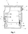
- Fig. 1 shows schematically an exhaust air dryer 1, which is an electronic in the upper part Has control device 2. To the right of this is an operating panel 10 with an operating element 11 arranged. Inside the exhaust air dryer 1 is a laundry drying room 8 arranged for receiving the laundry to be dried. The process air is blown by a blower 3 through the process air duct and a heater 4, the can be variably controlled by the control device 2. Immediately behind the Heating device 4, a temperature sensor 5 is arranged in the process air flow, with the Control device 2 is connected. The process airflow that is shown in the drawings Arrows is signaled, is behind the temperature sensor 5 in the laundry drying room 8 passed, which he leaves on the opposite side. The process air flow flows through there a lint filter 12 and is passed through an air outlet 13 to the outside. A further temperature sensor 6 is arranged behind the lint filter 12, which likewise is connected to the control device 2.
- FIG. 3 shows the time course of the heating power for the tumble dryer 1 from FIG. 1 and the output signals of the temperature sensors 5 and 6 are shown.
- the Course of the signal of the temperature sensor 6 for normal operation (signal S1) and in the event of the process air duct being laid (signal S2).
- the heating device 4 is short from the control device 2 at regular intervals switched off, so that in the heat output curve in the top curve in Fig. 3 briefly persistent Interruptions occur. These lead to brief temperature drops the process air, which are detected by the temperature sensor 5. Because the process airflow needs a certain amount of time from the heater 4 to the sensor 5, there occur the Temperature drops delayed to. However, this time delay is due to the short distance very small.
- the signal curve S1 (sensor 6) gives the temperature curve at the temperature sensor 6 for normal operation again. This occurs when detecting the temperature change with the temperature sensors 5 and 6 Time difference A on, among other things, the distance between the temperature sensors 5 and 6 and the flow rate of the process air flow depends.
- the Temperature sensors 5 and 6 have the same response to a temporal Compensate for delay in temperature detection.
- the process airflow inhibited for example by moving the lint filter 12, the flow rate increases from and the time difference too.
- the temperature sensor 6 the curve S2 (sensor 6) and the larger time difference B are measured.
- the Control device 2 can therefore, due to the time difference, the flow rate determine and thereby indirectly monitor the process air flow.
- a circulating air dryer 1 is shown schematically as a second embodiment.
- the difference to the exhaust air dryer from Fig. 1 is that the process air after the lint filter 12 passed through a heat exchanger 9 and then the blower again 3 is supplied.
- the moist process air stream is cooled in the heat exchanger 9, the moisture condenses and the process air stream is dried.
- a temperature sensor connected to the control device 2 7 provided between the heat exchanger 9 and the heating device 4. In this case, the heating device becomes regular, as in the tumble dryer from FIG. 1 Intervals switched off briefly.
- FIG. 4 shows the time course of the output signals for the circulating air dryer 1 from FIG. 2 of the temperature sensors 5 to 7 specified.
- the course of the heating output corresponds to that in Fig. 3 and is not shown in Fig. 4.
- the signal curves S (sensor 5), S1 (sensor 6) and S2 (sensor 6) correspond to those in Fig. 3.
- the output signal of the temperature sensor 7 is for normal operation due to the signal curve S1 (sensor 7) and for the case of laying the lint filter 12 represented by the signal curve S2 (sensor 7). Since an additional distance between the temperature sensors 6 and 7 there is a further time delay between the output signals of these sensors C, D on.
- the time differences used to determine the flow velocity A and B are, as in the previous case, between the acquisition of the Temperature change in the temperature sensors 5 and 6 and thus for the section of the process air duct between these temperature sensors.
- the temperature of sensors 6 and 7 is also evaluated.
- a certain Difference due to proper heat transfer in the heat exchanger 9 indicates.
- This difference can take into account the flow rate of the process air flow, which in this example is already by evaluating the time difference is known to be used to detect a fault in the heat exchanger 9. In general, if there is a proper temperature difference a proper function of the heat exchanger 9 can be assumed.
- the control device monitors 2 also whether a change in the heating power of the heating device 4 actually a temperature change is registered in all temperature sensors 5 and 6 or 5 to 7 can be. Otherwise, this can also indicate clogging of the process air duct or serve to escape the process air. In such a case, the Control device trigger an alarm signal.
Landscapes
- Engineering & Computer Science (AREA)
- Textile Engineering (AREA)
- Physics & Mathematics (AREA)
- Fluid Mechanics (AREA)
- General Physics & Mathematics (AREA)
- Control Of Washing Machine And Dryer (AREA)
- Drying Of Solid Materials (AREA)
Applications Claiming Priority (2)
| Application Number | Priority Date | Filing Date | Title |
|---|---|---|---|
| DE19842644 | 1998-09-17 | ||
| DE19842644A DE19842644A1 (de) | 1998-09-17 | 1998-09-17 | Verfahren zur Überwachung des Trocknungsluftstromes in einem Haushaltwäschetrockner sowie nach diesem Verfahren arbeitender Haushaltwäschetrockner |
Publications (3)
| Publication Number | Publication Date |
|---|---|
| EP0997571A2 true EP0997571A2 (fr) | 2000-05-03 |
| EP0997571A3 EP0997571A3 (fr) | 2001-10-31 |
| EP0997571B1 EP0997571B1 (fr) | 2003-12-03 |
Family
ID=7881307
Family Applications (1)
| Application Number | Title | Priority Date | Filing Date |
|---|---|---|---|
| EP99117668A Expired - Lifetime EP0997571B1 (fr) | 1998-09-17 | 1999-09-07 | Procédé pour surveiller l'air de séchage dans un séchoir à linge domestique et un séchoir à linge domestique utilisant un tel procédé |
Country Status (4)
| Country | Link |
|---|---|
| EP (1) | EP0997571B1 (fr) |
| AT (1) | ATE255653T1 (fr) |
| DE (2) | DE19842644A1 (fr) |
| ES (1) | ES2212436T3 (fr) |
Cited By (8)
| Publication number | Priority date | Publication date | Assignee | Title |
|---|---|---|---|---|
| EP1408151A1 (fr) * | 2002-10-10 | 2004-04-14 | Lg Electronics Inc. | Sèche-linge à condensation et procédé pour contrôler son opération |
| KR100511963B1 (ko) * | 2002-12-10 | 2005-09-02 | 엘지전자 주식회사 | 세탁기 |
| WO2007077072A1 (fr) * | 2005-12-29 | 2007-07-12 | BSH Bosch und Siemens Hausgeräte GmbH | Appareil menager destine a secher un article humide et procede de determination du degre d'humidite dans un tel appareil menager |
| EP1736592A3 (fr) * | 2005-06-23 | 2008-04-16 | Whirlpool Corporation | Sèche-linge automatique |
| EP1788141A3 (fr) * | 2005-11-16 | 2008-07-09 | BSH Bosch und Siemens Hausgeräte GmbH | Dispositif pour sécher du linge au moyen d'un courant d'air |
| EP1788142A3 (fr) * | 2005-11-16 | 2008-07-30 | BSH Bosch und Siemens Hausgeräte GmbH | Dispositif pour sécher du linge au moyen d'un courant d'air |
| DE102007061519A1 (de) * | 2007-12-20 | 2009-06-25 | BSH Bosch und Siemens Hausgeräte GmbH | Wäschetrocknungsgerät mit einer Feuchtigkeitsbestimmungseinrichtung und Ver-fahren zum Betreiben eines Wäschetrocknungsgeräts |
| DE102008040946A1 (de) * | 2008-08-01 | 2010-02-04 | BSH Bosch und Siemens Hausgeräte GmbH | Kondensationstrockner mit einer Wärmepumpe und Erkennung eines unzulässigen Betriebszustands sowie Verfahren zu seinem Betrieb |
Families Citing this family (12)
| Publication number | Priority date | Publication date | Assignee | Title |
|---|---|---|---|---|
| DE10065334A1 (de) | 2000-12-27 | 2002-07-04 | Bsh Bosch Siemens Hausgeraete | Waschmaschine mit Trockner |
| DE50302587D1 (de) | 2003-12-02 | 2006-05-04 | Dbk David & Baader Gmbh | Abdeckung für einen Wäschetrockner und Verfahren zu dessen Zusammenbau |
| ATE448351T1 (de) | 2004-05-07 | 2009-11-15 | Dbk David & Baader Gmbh | Heizbaugruppe für einen wäschetrockner |
| DE202004017677U1 (de) * | 2004-11-15 | 2005-01-05 | Elektromanufaktur Zangenstein Hanauer Gmbh & Co. Kgaa | Vorrichtung zum Erfassen eines Leitwerts eines Fluids |
| EP1974089B1 (fr) * | 2005-12-30 | 2009-02-25 | Arçelik Anonim Sirketi | Sechoir |
| DE102006025952A1 (de) * | 2006-06-02 | 2007-12-06 | BSH Bosch und Siemens Hausgeräte GmbH | Verfahren zur Erkennung des Stillstands einer Trommel in einem Trommeltrockner, und hierzu geeigneter Trommeltrockner |
| DE102006037239A1 (de) * | 2006-08-09 | 2008-02-14 | BSH Bosch und Siemens Hausgeräte GmbH | Verfahren und Wäschetrockner bzw. Waschtrockner zum Steuern des Trocknens von feuchter Wäsche |
| DE102008019920A1 (de) | 2008-04-21 | 2009-10-22 | BSH Bosch und Siemens Hausgeräte GmbH | Hausgerät insbesondere zum Trocknen eines Wäschepostens |
| DE102008049034A1 (de) | 2008-09-25 | 2010-04-01 | Curtius, Fritz | Ablufttrockner |
| MX2010008115A (es) | 2010-07-23 | 2012-01-23 | Mabe Sa De Cv | Metodo de secado con ahorro de energia. |
| DE102015221032A1 (de) * | 2015-10-28 | 2017-05-04 | BSH Hausgeräte GmbH | Wäschetrocknungsgerät aufweisen einen Prozessluftkreislauf und eine Volumenstrom-Bestimmungseinrichtung |
| CN110714310B (zh) * | 2018-06-27 | 2023-07-21 | 青岛海尔洗涤电器有限公司 | 衣物处理设备 |
Family Cites Families (3)
| Publication number | Priority date | Publication date | Assignee | Title |
|---|---|---|---|---|
| DE4337735C2 (de) * | 1992-11-25 | 1998-09-10 | Miele & Cie | Wäschetrockner mit einer Einrichtung zur Erkennung unzulässiger Betriebszustände sowie Verfahren zur Erkennung solcher Betriebszustände |
| DE4447270A1 (de) * | 1994-12-30 | 1996-07-04 | Bosch Siemens Hausgeraete | Verfahren zum Steuern von Trockenvorgängen in Haushalt-Wäschetrocknern |
| DE19533241C5 (de) * | 1995-09-08 | 2012-03-22 | Electrolux Rothenburg Gmbh Factory And Development | Verfahren und Vorrichtung zur thermischen Absicherung von Wäschetrocknern |
-
1998
- 1998-09-17 DE DE19842644A patent/DE19842644A1/de not_active Withdrawn
-
1999
- 1999-09-07 DE DE59907928T patent/DE59907928D1/de not_active Expired - Lifetime
- 1999-09-07 ES ES99117668T patent/ES2212436T3/es not_active Expired - Lifetime
- 1999-09-07 EP EP99117668A patent/EP0997571B1/fr not_active Expired - Lifetime
- 1999-09-07 AT AT99117668T patent/ATE255653T1/de not_active IP Right Cessation
Cited By (11)
| Publication number | Priority date | Publication date | Assignee | Title |
|---|---|---|---|---|
| EP1408151A1 (fr) * | 2002-10-10 | 2004-04-14 | Lg Electronics Inc. | Sèche-linge à condensation et procédé pour contrôler son opération |
| US6957501B2 (en) | 2002-10-10 | 2005-10-25 | Lg Electronics Inc. | Clothes dryer and method for controlling operation thereof |
| KR100511963B1 (ko) * | 2002-12-10 | 2005-09-02 | 엘지전자 주식회사 | 세탁기 |
| EP1736592A3 (fr) * | 2005-06-23 | 2008-04-16 | Whirlpool Corporation | Sèche-linge automatique |
| US8015726B2 (en) | 2005-06-23 | 2011-09-13 | Whirlpool Corporation | Automatic clothes dryer |
| EP1788141A3 (fr) * | 2005-11-16 | 2008-07-09 | BSH Bosch und Siemens Hausgeräte GmbH | Dispositif pour sécher du linge au moyen d'un courant d'air |
| EP1788142A3 (fr) * | 2005-11-16 | 2008-07-30 | BSH Bosch und Siemens Hausgeräte GmbH | Dispositif pour sécher du linge au moyen d'un courant d'air |
| WO2007077072A1 (fr) * | 2005-12-29 | 2007-07-12 | BSH Bosch und Siemens Hausgeräte GmbH | Appareil menager destine a secher un article humide et procede de determination du degre d'humidite dans un tel appareil menager |
| DE102007061519A1 (de) * | 2007-12-20 | 2009-06-25 | BSH Bosch und Siemens Hausgeräte GmbH | Wäschetrocknungsgerät mit einer Feuchtigkeitsbestimmungseinrichtung und Ver-fahren zum Betreiben eines Wäschetrocknungsgeräts |
| DE102008040946A1 (de) * | 2008-08-01 | 2010-02-04 | BSH Bosch und Siemens Hausgeräte GmbH | Kondensationstrockner mit einer Wärmepumpe und Erkennung eines unzulässigen Betriebszustands sowie Verfahren zu seinem Betrieb |
| US8484862B2 (en) | 2008-08-01 | 2013-07-16 | Bsh Bosch Und Siemens Hausgeraete Gmbh | Condensation dryer with a heat pump and recognition of an impermissible operating state and method for the operation thereof |
Also Published As
| Publication number | Publication date |
|---|---|
| DE19842644A1 (de) | 2000-03-23 |
| DE59907928D1 (de) | 2004-01-15 |
| ATE255653T1 (de) | 2003-12-15 |
| ES2212436T3 (es) | 2004-07-16 |
| EP0997571B1 (fr) | 2003-12-03 |
| EP0997571A3 (fr) | 2001-10-31 |
Similar Documents
| Publication | Publication Date | Title |
|---|---|---|
| EP0997571B1 (fr) | Procédé pour surveiller l'air de séchage dans un séchoir à linge domestique et un séchoir à linge domestique utilisant un tel procédé | |
| EP2035617B1 (fr) | Procédé pour détecter l'arrêt d'un tambour dans un séchoir à tambour et séchoir à tambour approprié à cet effet | |
| EP0889155B1 (fr) | Procédé pour détecter un disfonctionnement dans un sèche linge sèche linge utilisant un tel procédé | |
| EP2052106B1 (fr) | Procédé et appareil ménager pour sécher du linge humide | |
| EP2227585A1 (fr) | Sèche-linge doté d'un dispositif de détermination d'humidité et procédé permettant de faire fonctionner un sèche-linge | |
| DE4447270A1 (de) | Verfahren zum Steuern von Trockenvorgängen in Haushalt-Wäschetrocknern | |
| EP2333149A1 (fr) | Sèche-linge doté d'un capteur de température ambiante | |
| DE4434205A1 (de) | Wäschetrockner | |
| DE69203290T2 (de) | Wäschetrockner. | |
| EP0679754A2 (fr) | Procédé et dispositif pour le traitement de produits textiles pendant le séchage | |
| DE3738033A1 (de) | Vorrichtung zur ueberwachung fuer einen haushalt-waeschetrockner | |
| WO2014095465A1 (fr) | Sèche-linge électroménager pourvu d'un dispositif de nettoyage de filtre à peluches | |
| DE4034273A1 (de) | Waeschetrockner und verfahren zur ueberwachung eines waeschetrockners | |
| EP2734667B1 (fr) | Procede de fonctionnement d'un seche linge a pompe a chaleur | |
| EP3392396A1 (fr) | Séchoir à tambour avec fonction de séchage de l'air dans la chambre | |
| DE102013104124B4 (de) | Verfahren zur Erkennung einer wenigstens teilweisen Verstopfung eines Prozessluftkanals in einemTrockner und Trockner zur Durchführung eines solchen Verfahrens | |
| DE19704213C1 (de) | System zur Erkennung unzulässiger Betriebszustände in einem Wäschetrockner | |
| DE4337735C2 (de) | Wäschetrockner mit einer Einrichtung zur Erkennung unzulässiger Betriebszustände sowie Verfahren zur Erkennung solcher Betriebszustände | |
| DE4211012C2 (de) | Verfahren und Vorrichtung zum Steuern eines Trocknungsvorganges | |
| EP1270475B1 (fr) | Surveillance d'une bande fibreuse | |
| EP0796751B1 (fr) | Dispositif de climatisation | |
| DE19533241C5 (de) | Verfahren und Vorrichtung zur thermischen Absicherung von Wäschetrocknern | |
| WO2008043705A1 (fr) | Sèche-linge doté d'un dispositif d'affichage qui affiche le dégré d'encrassement | |
| WO2017071877A1 (fr) | Sèche-linge comprenant un circuit d'air de traitement et dispositif de détermination de débit volumétrique | |
| DE102006005808A1 (de) | Verfahren zur Erkennung eines kritischen Betriebszustandes bei einer Widerstandsheizung, sowie entsprechendes Hausgerät |
Legal Events
| Date | Code | Title | Description |
|---|---|---|---|
| PUAI | Public reference made under article 153(3) epc to a published international application that has entered the european phase |
Free format text: ORIGINAL CODE: 0009012 |
|
| AK | Designated contracting states |
Kind code of ref document: A2 Designated state(s): AT BE CH CY DE DK ES FI FR GB GR IE IT LI LU MC NL PT SE |
|
| AX | Request for extension of the european patent |
Free format text: AL;LT;LV;MK;RO;SI |
|
| PUAL | Search report despatched |
Free format text: ORIGINAL CODE: 0009013 |
|
| AK | Designated contracting states |
Kind code of ref document: A3 Designated state(s): AT BE CH CY DE DK ES FI FR GB GR IE IT LI LU MC NL PT SE |
|
| AX | Request for extension of the european patent |
Free format text: AL;LT;LV;MK;RO;SI |
|
| 17P | Request for examination filed |
Effective date: 20020502 |
|
| AKX | Designation fees paid |
Free format text: AT BE CH CY DE DK ES FI FR GB GR IE IT LI LU MC NL PT SE |
|
| AXX | Extension fees paid |
Free format text: SI PAYMENT 20020502 |
|
| GRAH | Despatch of communication of intention to grant a patent |
Free format text: ORIGINAL CODE: EPIDOS IGRA |
|
| GRAS | Grant fee paid |
Free format text: ORIGINAL CODE: EPIDOSNIGR3 |
|
| GRAA | (expected) grant |
Free format text: ORIGINAL CODE: 0009210 |
|
| AK | Designated contracting states |
Kind code of ref document: B1 Designated state(s): AT BE CH CY DE DK ES FI FR GB GR IE IT LI LU MC NL PT SE |
|
| AX | Request for extension of the european patent |
Extension state: SI |
|
| PG25 | Lapsed in a contracting state [announced via postgrant information from national office to epo] |
Ref country code: IE Free format text: LAPSE BECAUSE OF FAILURE TO SUBMIT A TRANSLATION OF THE DESCRIPTION OR TO PAY THE FEE WITHIN THE PRESCRIBED TIME-LIMIT Effective date: 20031203 Ref country code: FI Free format text: LAPSE BECAUSE OF FAILURE TO SUBMIT A TRANSLATION OF THE DESCRIPTION OR TO PAY THE FEE WITHIN THE PRESCRIBED TIME-LIMIT Effective date: 20031203 Ref country code: CY Free format text: LAPSE BECAUSE OF FAILURE TO SUBMIT A TRANSLATION OF THE DESCRIPTION OR TO PAY THE FEE WITHIN THE PRESCRIBED TIME-LIMIT Effective date: 20031203 |
|
| REG | Reference to a national code |
Ref country code: GB Ref legal event code: FG4D Free format text: NOT ENGLISH |
|
| REG | Reference to a national code |
Ref country code: CH Ref legal event code: NV Representative=s name: SERVOPATENT GMBH Ref country code: CH Ref legal event code: EP |
|
| GBT | Gb: translation of ep patent filed (gb section 77(6)(a)/1977) |
Effective date: 20031203 |
|
| REG | Reference to a national code |
Ref country code: IE Ref legal event code: FG4D Free format text: GERMAN |
|
| REF | Corresponds to: |
Ref document number: 59907928 Country of ref document: DE Date of ref document: 20040115 Kind code of ref document: P |
|
| RAP2 | Party data changed (patent owner data changed or rights of a patent transferred) |
Owner name: BSH BOSCH UND SIEMENS HAUSGERAETE GMBH |
|
| PG25 | Lapsed in a contracting state [announced via postgrant information from national office to epo] |
Ref country code: GR Free format text: LAPSE BECAUSE OF FAILURE TO SUBMIT A TRANSLATION OF THE DESCRIPTION OR TO PAY THE FEE WITHIN THE PRESCRIBED TIME-LIMIT Effective date: 20040303 Ref country code: DK Free format text: LAPSE BECAUSE OF FAILURE TO SUBMIT A TRANSLATION OF THE DESCRIPTION OR TO PAY THE FEE WITHIN THE PRESCRIBED TIME-LIMIT Effective date: 20040303 |
|
| REG | Reference to a national code |
Ref country code: SE Ref legal event code: TRGR |
|
| NLT2 | Nl: modifications (of names), taken from the european patent patent bulletin |
Owner name: BSH BOSCH UND SIEMENS HAUSGERAETE GMBH |
|
| ET | Fr: translation filed | ||
| REG | Reference to a national code |
Ref country code: ES Ref legal event code: FG2A Ref document number: 2212436 Country of ref document: ES Kind code of ref document: T3 |
|
| REG | Reference to a national code |
Ref country code: IE Ref legal event code: FD4D |
|
| PG25 | Lapsed in a contracting state [announced via postgrant information from national office to epo] |
Ref country code: LU Free format text: LAPSE BECAUSE OF NON-PAYMENT OF DUE FEES Effective date: 20040907 |
|
| PG25 | Lapsed in a contracting state [announced via postgrant information from national office to epo] |
Ref country code: MC Free format text: LAPSE BECAUSE OF NON-PAYMENT OF DUE FEES Effective date: 20040930 Ref country code: BE Free format text: LAPSE BECAUSE OF NON-PAYMENT OF DUE FEES Effective date: 20040930 |
|
| PLBE | No opposition filed within time limit |
Free format text: ORIGINAL CODE: 0009261 |
|
| STAA | Information on the status of an ep patent application or granted ep patent |
Free format text: STATUS: NO OPPOSITION FILED WITHIN TIME LIMIT |
|
| 26N | No opposition filed |
Effective date: 20040906 |
|
| BERE | Be: lapsed |
Owner name: BOSCH UND SIEMENS HAUSGERATE G.M.B.H. *BSH Effective date: 20040930 |
|
| BERE | Be: lapsed |
Owner name: BOSCH UND SIEMENS HAUSGERATE G.M.B.H. *BSH Effective date: 20040930 |
|
| PG25 | Lapsed in a contracting state [announced via postgrant information from national office to epo] |
Ref country code: PT Free format text: LAPSE BECAUSE OF NON-PAYMENT OF DUE FEES Effective date: 20040503 |
|
| PGFP | Annual fee paid to national office [announced via postgrant information from national office to epo] |
Ref country code: ES Payment date: 20080922 Year of fee payment: 10 Ref country code: CH Payment date: 20080923 Year of fee payment: 10 |
|
| PGFP | Annual fee paid to national office [announced via postgrant information from national office to epo] |
Ref country code: NL Payment date: 20080922 Year of fee payment: 10 Ref country code: IT Payment date: 20080924 Year of fee payment: 10 Ref country code: FR Payment date: 20080917 Year of fee payment: 10 Ref country code: AT Payment date: 20080919 Year of fee payment: 10 |
|
| PGFP | Annual fee paid to national office [announced via postgrant information from national office to epo] |
Ref country code: SE Payment date: 20080923 Year of fee payment: 10 |
|
| REG | Reference to a national code |
Ref country code: CH Ref legal event code: PCAR Free format text: SIEMENS SCHWEIZ AG;INTELLECTUAL PROPERTY FREILAGERSTRASSE 40;8047 ZUERICH (CH) |
|
| REG | Reference to a national code |
Ref country code: NL Ref legal event code: V1 Effective date: 20100401 |
|
| REG | Reference to a national code |
Ref country code: CH Ref legal event code: PL |
|
| EUG | Se: european patent has lapsed | ||
| REG | Reference to a national code |
Ref country code: FR Ref legal event code: ST Effective date: 20100531 |
|
| PG25 | Lapsed in a contracting state [announced via postgrant information from national office to epo] |
Ref country code: AT Free format text: LAPSE BECAUSE OF NON-PAYMENT OF DUE FEES Effective date: 20090907 |
|
| PG25 | Lapsed in a contracting state [announced via postgrant information from national office to epo] |
Ref country code: NL Free format text: LAPSE BECAUSE OF NON-PAYMENT OF DUE FEES Effective date: 20100401 Ref country code: FR Free format text: LAPSE BECAUSE OF NON-PAYMENT OF DUE FEES Effective date: 20090930 |
|
| PG25 | Lapsed in a contracting state [announced via postgrant information from national office to epo] |
Ref country code: LI Free format text: LAPSE BECAUSE OF NON-PAYMENT OF DUE FEES Effective date: 20090930 Ref country code: CH Free format text: LAPSE BECAUSE OF NON-PAYMENT OF DUE FEES Effective date: 20090930 |
|
| PG25 | Lapsed in a contracting state [announced via postgrant information from national office to epo] |
Ref country code: IT Free format text: LAPSE BECAUSE OF NON-PAYMENT OF DUE FEES Effective date: 20090907 |
|
| PG25 | Lapsed in a contracting state [announced via postgrant information from national office to epo] |
Ref country code: SE Free format text: LAPSE BECAUSE OF NON-PAYMENT OF DUE FEES Effective date: 20090908 |
|
| REG | Reference to a national code |
Ref country code: ES Ref legal event code: FD2A Effective date: 20110714 |
|
| PG25 | Lapsed in a contracting state [announced via postgrant information from national office to epo] |
Ref country code: ES Free format text: LAPSE BECAUSE OF NON-PAYMENT OF DUE FEES Effective date: 20110704 |
|
| PG25 | Lapsed in a contracting state [announced via postgrant information from national office to epo] |
Ref country code: ES Free format text: LAPSE BECAUSE OF NON-PAYMENT OF DUE FEES Effective date: 20090908 |
|
| PGFP | Annual fee paid to national office [announced via postgrant information from national office to epo] |
Ref country code: GB Payment date: 20110923 Year of fee payment: 13 Ref country code: DE Payment date: 20110930 Year of fee payment: 13 |
|
| GBPC | Gb: european patent ceased through non-payment of renewal fee |
Effective date: 20120907 |
|
| PG25 | Lapsed in a contracting state [announced via postgrant information from national office to epo] |
Ref country code: DE Free format text: LAPSE BECAUSE OF NON-PAYMENT OF DUE FEES Effective date: 20130403 Ref country code: GB Free format text: LAPSE BECAUSE OF NON-PAYMENT OF DUE FEES Effective date: 20120907 |
|
| REG | Reference to a national code |
Ref country code: DE Ref legal event code: R119 Ref document number: 59907928 Country of ref document: DE Effective date: 20130403 |