EP0997577A1 - Caisse de tête - Google Patents
Caisse de tête Download PDFInfo
- Publication number
- EP0997577A1 EP0997577A1 EP99112933A EP99112933A EP0997577A1 EP 0997577 A1 EP0997577 A1 EP 0997577A1 EP 99112933 A EP99112933 A EP 99112933A EP 99112933 A EP99112933 A EP 99112933A EP 0997577 A1 EP0997577 A1 EP 0997577A1
- Authority
- EP
- European Patent Office
- Prior art keywords
- headbox according
- headbox
- nozzle
- central part
- nozzle wall
- Prior art date
- Legal status (The legal status is an assumption and is not a legal conclusion. Google has not performed a legal analysis and makes no representation as to the accuracy of the status listed.)
- Granted
Links
- 239000000835 fiber Substances 0.000 claims description 4
- 238000005452 bending Methods 0.000 claims description 3
- 230000003068 static effect Effects 0.000 claims description 3
- 239000000725 suspension Substances 0.000 claims description 2
- 238000010521 absorption reaction Methods 0.000 claims 1
- 238000009795 derivation Methods 0.000 claims 1
- 238000000926 separation method Methods 0.000 claims 1
- 238000007599 discharging Methods 0.000 abstract 1
- 238000010276 construction Methods 0.000 description 8
- 239000000463 material Substances 0.000 description 6
- 210000000481 breast Anatomy 0.000 description 2
- 230000004913 activation Effects 0.000 description 1
- 230000000694 effects Effects 0.000 description 1
- 230000005484 gravity Effects 0.000 description 1
- 239000003351 stiffener Substances 0.000 description 1
Images



Classifications
-
- D—TEXTILES; PAPER
- D21—PAPER-MAKING; PRODUCTION OF CELLULOSE
- D21F—PAPER-MAKING MACHINES; METHODS OF PRODUCING PAPER THEREON
- D21F1/00—Wet end of machines for making continuous webs of paper
- D21F1/02—Head boxes of Fourdrinier machines
- D21F1/026—Details of the turbulence section
-
- D—TEXTILES; PAPER
- D21—PAPER-MAKING; PRODUCTION OF CELLULOSE
- D21F—PAPER-MAKING MACHINES; METHODS OF PRODUCING PAPER THEREON
- D21F1/00—Wet end of machines for making continuous webs of paper
- D21F1/02—Head boxes of Fourdrinier machines
-
- D—TEXTILES; PAPER
- D21—PAPER-MAKING; PRODUCTION OF CELLULOSE
- D21F—PAPER-MAKING MACHINES; METHODS OF PRODUCING PAPER THEREON
- D21F1/00—Wet end of machines for making continuous webs of paper
- D21F1/02—Head boxes of Fourdrinier machines
- D21F1/028—Details of the nozzle section
Definitions
- the invention relates to a headbox for a paper machine with a Inlet part, a central part that extends across the machine width and a nozzle that extends across the machine width at least one is transverse to the longitudinal flow direction across the machine width extending continuous wall.
- the central part can in particular by essentially vertical Components are formed that penetrate the entire material flow and thereby on compressive and / or tensile forces in the vertical direction over its the entire width are resilient and extend across the machine width.
- Headboxes of this type are known, for example, from EP 0 323 468 B1 or known from EP 0 631 011 A1. These known headboxes are each overall in the transverse direction, d. H. transverse to the longitudinal flow direction in Sections divided.
- the advantage of such a structure is that it is independent of width of the construction and in the by the handy reproducible parts resulting in cost reduction.
- the practical one Realization of such designs is difficult. So in the areas affected by the flow a relatively large effort operated in order to accumulate deposits at the section boundaries To prevent fibers and the like. The cost advantage previously achieved is canceled again.
- the invention has for its object an improved cost-effective To create headbox of the type mentioned, in which the previously mentioned problems are eliminated.
- At least essentially only such can elements of the headbox that come into contact with the material flow in a modular design, which are not adjustable against each other are.
- width-extending components are the aforementioned ones Taking advantage of a modular structure while on the other deposits of fibers and the like practically without additional effort at the adjustment joints are excluded. So are in particular on that Central part of the following flow-carrying parts are not of modular design, while the support of at least one nozzle wall over several over separate support devices are distributed across the machine width. In order to the expansion forces that occur as a result of the internal pressure of the nozzle recorded relatively evenly across the width. Temperature differences in the support devices, as are known from practice due to the division into individual modules, there is no longer any effect on the accuracy of the nozzle gap.
- the central part is across the machine width divided into sections.
- the inlet part can be divided into sections across the machine width.
- the central part can be designed, for example, as a turbulence generator and preferably comprise a plurality of step diffusers.
- At least one nozzle wall prefferably be transverse to one Axis extending flow direction pivotable and / or in the flow direction slidably mounted.
- At least one continuous nozzle wall supported by a plurality of separate support devices is provided, the bending stiffness of which in the transverse direction, ie in the direction of the machine width, in a range from approximately 5 ⁇ 10 9 Nmm 2 to approximately 7.5 ⁇ 10 10 Nmm 2 per 100 mm in the flow direction extending wall length. This ensures that the sections are "decoupled" with regard to the deformation.
- At least one is preferably provided via a plurality of separate support devices supported continuous nozzle wall over the individual support devices can be positioned in sections.
- Headbox are the different support devices individually with connected to the central part and the relevant nozzle wall.
- At least one is pivotable Support device assigned to the nozzle wall using a static model corresponds to at least three bars spaced from the central part and the pivotable nozzle wall at least substantially in one Node are brought together, with at least one rod nearby of the inlet part and at least one further rod near the pivot axis acts on the central part, and at least a third rod on the pivoted nozzle wall acts, and that the at least three rods a respective support device in or symmetrical to a plane are arranged perpendicular to the direction of the machine width and in Longitudinal flow direction.
- the length of at least one rod can expediently be changed.
- the support devices acting on the nozzle wall can e.g. be connected to the central part via a base plate.
- At least one support device is the connection to the central part and / or support part producing the nozzle wall.
- a support part can, for example, from a one-piece cast or welded part consist.
- the nozzle walls are expediently without extending in the transverse direction Stiffening ribs and stiffening profiles formed.
- the headbox is preferably one imaginary transverse axis provided in the area of the nozzle end pivotable, which acts directly or indirectly on the central part.
- the point of impact of the material jet on a downstream drainage unit can be set.
- the swivel axis of the swivel headbox can be different Be defined.
- two can be between each a headbox sidewall and a side support Swivel bearings can be provided.
- the preferably in Area of the nozzle end provided by the pivot axis Guides must be defined in which the headbox is stored accordingly is.
- the headbox is supported on at least one support device, the least two support units includes, in particular two in the flow direction Define different points from the end of the nozzle and perform different strokes so that the headbox is approximately pivotable about the nozzle end.
- the central part can have one of the stiffeners of the central part on the inflow side and / or serving as a fastening element for further functional elements
- Inlet plate can be assigned, which is transverse to the flow direction extends over at least substantially the entire width of the central part.
- Such an inlet plate can in particular on the recording be involved in the forces of the hydraulic pressure of the material flow.
- Headbox is at least one nozzle wall on one attached to the central part Support part generally slidably mounted in the flow direction.
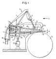
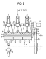
- the headbox shown purely schematically in Figures 1 and 2 for a paper machine comprises an inlet part 2, a central part 1 and one Nozzle 56.
- the nozzle 56 is provided with two continuous walls 4, 5 which extend transversely to the longitudinal flow direction across the machine width and to which a plurality of separate support devices 14 and 14 ' , respectively, are allocated to absorb and dissipate nozzle expansion forces.
- the inlet part 2 is via individual supply holes 18 with fiber suspension provided.
- the supply holes 18 are either with longer individual tubes 3 or directly with a common one Distribution pipe 19 connected, which is substantially parallel to the outlet gap is arranged.
- the central part 1 is designed as a turbulence generator in the present case and provided with several step diffusers. Over the upper nozzle wall 4 and the lower nozzle wall 5, the flow up to one Beam exit 15 out where the material jet finally at an angle ⁇ emerges from the horizontal.
- the upper continuous nozzle wall 4 is transverse to the longitudinal flow direction extending near the central block or Central part 1 arranged axis 6 pivotally mounted.
- axis 6 pivotally mounted.
- the machine width defines the hinge or joint divided into sections. This is the hinge defining the pivot axis 6 in the Support devices 14 associated supports 7 stored.
- the pivotable upper nozzle wall is in the direction of the jet outlet 15 above also associated with the support devices 14 the supports 7 articulated jacks 8 supported, each via a Attack bridge element 9 on nozzle wall 4.
- the resulting lines of force K are each a bridge member 9, a lifting gear 8 and a support 7 comprehensive support device 14 each in a direction perpendicular to the direction of the mesh width, plane oriented in the direction of flow.
- the supports 7 are over a corresponding number of base plates 7a or at least a common base plate with the central part 1 firmly connected and screwed, for example. Other than that, these are Supports 7 not connected to each other transversely to the flow direction.
- support devices assigned to the lower nozzle wall 5 via one or more base plates 10a with the central part 1 be connected.
- drive pins 20 are next to one another horizontal lifting gear 8 via a transverse to the direction of flow the machine width divided into sections drive shaft 21 exclusively Torsionally connected to each other, so that with an actuation of a assigned drive 22, the nozzle wall 4 (see also FIG. 1) via the entire width is moved in the same way, without other tensioning forces are transmitted from the drive shaft 21.
- the lower nozzle wall 5 can basically be the same as that upper nozzle wall 4 are supported, for which purpose again in particular distributed the machine width, each provided with a lifting gear 12 modular support devices 14 'can be provided.
- a rigid, designed as a support module 10 takes the hydraulic Forces of the nozzle wall 5 and directs them to the one forming a central block Central part 1 further. By lining up several support devices The lower nozzle wall becomes 14 'across the machine width 5 supported evenly across the entire machine width.
- a division length is in a range of approximately 50 to about 1000 mm and preferably in a range from about 200 to 500 mm conceivable.
- the central part 1 gives the entire headbox structure the desired Stiffness. This can be increased by the fact that a in the central part 1 inlet plate 11 on the inflow side is preferred extends beyond the height of the inlet part 2. This is preferred at least essentially over the entire width of the central part 1 extending inlet plate 11 can simultaneously as a structural component serve the inlet part 2.
- the entire headbox is around one in the area of the nozzle end or Beam exit 15 provided axis 24a pivotally mounted so that a corresponding beam angle adjustment is possible.
- a journal bearing 24 is assigned to each side wall 23 of the headbox, which is attached to a support 25.
- the supports 25 are for example on a chair and / or a headbox foundation appropriate.
- the pivoting movement is from the at least one lifting gear 12 causes this advantageously in the area of the axis of gravity the headbox is positioned.
- Fig. 3 shows a schematic, partially sectioned side view of a Embodiment of an overall pivotable headbox.
- the headbox on at least one support device 12 stored, which comprises at least two support units 40, 41, the two in Flow direction a different distance from the nozzle end Define or have beam outlets 15 and different ones Carry out strokes so that the headbox approx the nozzle end 15 is pivotable.
- the two attack Support units 40, 41 on the lower rigid support part 10.
- this embodiment can have the same structure as that according to Figures 1 and 2, with mutually corresponding parts same reference numerals are assigned.
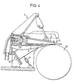
- Fig. 4 shows a schematic, partially sectioned side view of a another embodiment of a pivotable headbox.
- the case is that which is preferably provided in the region of the nozzle end 15 Pivot axis of the headbox defined by guides 30 in which the headbox is stored accordingly.
- the headbox is then around defined by the guides 30, located in the area of the nozzle end imaginary axis swiveling.
- this embodiment can again have the same structure have like those according to Figures 1 and 2, with corresponding to each other Parts are assigned the same reference numerals again.
- FIGs 5 and 6 is another in a purely schematic representation Embodiment of a headbox shown, in which the lower nozzle wall 5 slidably supported on the support part 10 and relative to this in Flow longitudinal direction is displaceable.
- the nozzle wall is 5 via at least one, for example mechanical, hydraulic and / or pneumatic adjustment device 48 can be moved in the desired direction.
- This adjusting device 48 engages in the present case Support part 10 and the nozzle wall 5.
- the adjustment device comprises 48 two pivot pins 50 mounted in the support part 10, each have an eccentric extension 51 which in one in the nozzle wall 4 provided groove 55 engages.
- the pivot pins 50 carry levers 52 integrated swiveling nuts 53, which have a common adjusting spindle 54 (see FIG. 6) can be actuated with opposing threads.
- the eccentric attachments 51 are each Pivot pin 50 releasable.
- this embodiment can have the same structure again as those according to Figures 1 and 2, with corresponding to each other Parts are assigned the same reference numerals again.
- FIG. 5 is a purely schematic representation of FIG Embodiment for a respective support device 14 shown as it especially in the other embodiments of the headbox is conceivable.
- the support devices assigned to the pivotable nozzle wall 4 14 corresponding to a static model with the present one Case three rods 57, 58, 59, which are at a distance from the central part 1 and the pivotable nozzle wall 4 at least substantially in the Node 60 are brought together, the rod 57 near the Inlet part 2 acts on the central part 1, the central rod 58 near the Swivel axis 6 and the third rod 59 on the pivotally mounted nozzle wall 4 acts.
- the rods 57, 58 and 59 are each a supporting device 14 arranged in or also symmetrically to a plane, which are perpendicular to the direction of the machine width and in the direction of flow runs. In the present case, the bars 57, 58 and 59 are in one perpendicular to the direction of the machine width and in the longitudinal direction of the flow current level, d. H. in the drawing plane of Figure 5, arranged.
- the near reaches Swivel axis 6 provided rod 58 indirectly or directly on Central part 1.
- Fig. 7 shows a schematic, partially sectioned side view, a further embodiment of a headbox comparable to that of FIG. 5 with a schematically represented, by a framework construction formed support device 14, the near the pivot axis 6th provided middle rod 58, however, directly or indirectly on the attacks around the axis 6 pivotally mounted nozzle wall 4.
- this embodiment has the same structure as that according to Figures 5 and 6, with corresponding parts having the same reference numerals assigned.
- Fig. 8 shows a schematic, partially sectioned side view further embodiment of a headbox comparable to that of FIG. 5 with upper ones, each formed by a framework construction Support devices 14.
- the view x of the anchor of a rod end shown on the nozzle wall is the view x of the anchor of a rod end shown on the nozzle wall.
- this embodiment can have the same structure as that 5, with parts corresponding to one another again being the same Reference symbols are assigned.
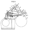
- Fig. 9 shows a schematic, partially sectioned side view further embodiment of a headbox comparable to that of FIG. 5, in the two of the supports distributed across the machine width 14 are shown.
- Fig. 9 there is also a coordinate system with the axes X, Y and Z indicated.
- the X direction falls here along with the width direction of the paper machine, while the Y direction coincides with the longitudinal flow direction.
- the Z direction runs perpendicular to the X-Y plane.
- the supports are 14 arranged one behind the other in the X direction, while the Bars 57, 58 and 59 of a respective support device 14 each in one y-z plane.
- the supported on these separate support devices 14 continuous upper nozzle wall 4 is thus over the individual Support devices 14 can be positioned in sections.
- the middle rods 58 directly or indirectly grip on the central part 1.
- the middle one Rod 58 of a respective support device 14 indirectly or directly on the pivotably mounted nozzle wall 4 or on the pivot axis 6 defining joint attacks.
- this embodiment can again have the same structure as the previous embodiments, with each other corresponding Parts are provided with the same reference numerals.
- an equalization of the Voltage-serving grooves 62 may be provided, such as this can be seen from FIG. 9.
Landscapes
- Paper (AREA)
- Magnetic Resonance Imaging Apparatus (AREA)
- Handling Of Sheets (AREA)
Applications Claiming Priority (2)
| Application Number | Priority Date | Filing Date | Title |
|---|---|---|---|
| DE19845722A DE19845722A1 (de) | 1998-10-05 | 1998-10-05 | Stoffauflauf |
| DE19845722 | 1998-10-05 |
Publications (2)
| Publication Number | Publication Date |
|---|---|
| EP0997577A1 true EP0997577A1 (fr) | 2000-05-03 |
| EP0997577B1 EP0997577B1 (fr) | 2003-11-12 |
Family
ID=7883392
Family Applications (1)
| Application Number | Title | Priority Date | Filing Date |
|---|---|---|---|
| EP99112933A Expired - Lifetime EP0997577B1 (fr) | 1998-10-05 | 1999-07-05 | Caisse de tête |
Country Status (4)
| Country | Link |
|---|---|
| US (1) | US6248214B1 (fr) |
| EP (1) | EP0997577B1 (fr) |
| AT (1) | ATE254207T1 (fr) |
| DE (2) | DE19845722A1 (fr) |
Cited By (2)
| Publication number | Priority date | Publication date | Assignee | Title |
|---|---|---|---|---|
| DE102008042032A1 (de) | 2008-09-12 | 2010-03-18 | Voith Patent Gmbh | Turbulenzerzeuger für einen Stoffauflauf, Stoffauflauf und Verfahren zur Herstellung des Turbulenzerzeugers |
| DE102009045221A1 (de) | 2009-09-30 | 2011-03-31 | Voith Patent Gmbh | Turbulenzerzeuger für einen Stoffauflauf, Stoffauflauf und Verfahren zur Herstellung des Turbulenzerzeugers |
Families Citing this family (15)
| Publication number | Priority date | Publication date | Assignee | Title |
|---|---|---|---|---|
| DE10060328C1 (de) * | 2000-12-04 | 2001-12-20 | Pama Papiermaschinen Gmbh | Hochturbulenz-Stoffauflauf, insbesondere für Hochgeschwindigkeits-Papiermaschinen |
| DE102004038560A1 (de) * | 2004-08-06 | 2006-03-16 | Voith Paper Patent Gmbh | Stoffauflauf für eine Maschine zur Herstellung einer Faserstoffbahn, insbesondere einer Papier- oder Kartonbahn |
| US8075737B2 (en) * | 2006-01-30 | 2011-12-13 | Paperchine Inc. | Headbox apparatus for a papermaking machine |
| US7794570B2 (en) * | 2006-01-30 | 2010-09-14 | Paperchine Inc. | Headbox apparatus for a papermaking machine |
| US7897016B2 (en) * | 2006-01-30 | 2011-03-01 | James Leroy Ewald | Headbox apparatus for a papermaking machine |
| WO2008082546A1 (fr) * | 2006-12-19 | 2008-07-10 | Paperchine Inc. | Appareil de caisse de tête pour une machine à papier |
| DE102007033938A1 (de) * | 2007-07-20 | 2009-01-22 | Voith Patent Gmbh | Vorrichtung zur Herstellung einer Faserstoffbahn |
| US8770139B2 (en) | 2009-03-03 | 2014-07-08 | United States Gypsum Company | Apparatus for feeding cementitious slurry onto a moving web |
| DE102009045166A1 (de) * | 2009-09-30 | 2011-03-31 | Voith Patent Gmbh | Stoffauflauf für eine Maschine zur Herstellung einer Faserstoffbahn, insbesondere einer Papier- oder Kartonbahn |
| US9422665B2 (en) | 2012-09-04 | 2016-08-23 | Paperchine Inc. | Headbox apparatus |
| US10272399B2 (en) | 2016-08-05 | 2019-04-30 | United States Gypsum Company | Method for producing fiber reinforced cementitious slurry using a multi-stage continuous mixer |
| US11224990B2 (en) | 2016-08-05 | 2022-01-18 | United States Gypsum Company | Continuous methods of making fiber reinforced concrete panels |
| US10981294B2 (en) | 2016-08-05 | 2021-04-20 | United States Gypsum Company | Headbox and forming station for fiber-reinforced cementitious panel production |
| US11173629B2 (en) | 2016-08-05 | 2021-11-16 | United States Gypsum Company | Continuous mixer and method of mixing reinforcing fibers with cementitious materials |
| CN114921994B (zh) * | 2022-05-30 | 2025-12-05 | 江苏聚源新材料科技有限公司 | 一种复合木浆水刺无纺布加工用流浆箱 |
Citations (2)
| Publication number | Priority date | Publication date | Assignee | Title |
|---|---|---|---|---|
| US3738910A (en) * | 1972-02-08 | 1973-06-12 | Allis Chalmers | Nozzle adjusting arrangement for a papermaking machine headbox |
| EP0323468B1 (fr) * | 1986-08-23 | 1990-06-06 | J.M. Voith GmbH | Caisse de tete |
Family Cites Families (13)
| Publication number | Priority date | Publication date | Assignee | Title |
|---|---|---|---|---|
| US1775905A (en) | 1928-03-20 | 1930-09-16 | American Voith Contact Co Inc | Stock inlet for paper machines |
| US3309264A (en) * | 1964-01-17 | 1967-03-14 | Beloit Corp | Flow distributor for a papermaking machine |
| US3313681A (en) | 1964-08-27 | 1967-04-11 | Beloit Corp | Headbox with bottom wall having controllable deflection |
| CH564640A5 (fr) * | 1973-04-17 | 1975-07-31 | Escher Wyss Gmbh | |
| US4133715A (en) * | 1977-03-29 | 1979-01-09 | Beloit Corporation | Headbox and holders for floating slice chamber dividers |
| FI61737C (fi) * | 1980-12-17 | 1982-09-10 | Valmet Oy | Reglerbar inloppslaoda foer pappersmaskin |
| FI72764C (fi) * | 1986-02-13 | 1987-07-10 | Valmet Oy | Spetslist i inloppslaodan av en pappersmaskin. |
| DE3723922C2 (de) * | 1987-07-18 | 1993-10-14 | Trefz Wolfgang Dipl Ing Fh | Turbulenzerzeuger für den Stoffauflauf einer Papiermaschine |
| FI84920C (fi) * | 1988-05-27 | 1992-02-10 | Valmet Ahlstroem Inc | Hydraulisk inloppslaoda i pappers- eller kartongmaskin. |
| DE9102095U1 (de) | 1991-02-22 | 1991-05-16 | J.M. Voith Gmbh, 7920 Heidenheim | Kanalwand, insbesondere für einen Papiermaschinen-Stoffauflauf |
| EP0529174B1 (fr) * | 1991-08-22 | 1996-04-17 | Beloit Technologies, Inc. | Caisse de tête supporté par un éjecteur de fluides |
| DE4318430C2 (de) * | 1993-06-03 | 1997-03-27 | Schultz Hans Joachim Dr Ing | Stoffauflaufsystem einer Papiermaschine |
| DE4328997C2 (de) * | 1993-08-28 | 1998-07-02 | Voith Gmbh J M | Naßpartie eines Doppelsieb-GAP-Formers |
-
1998
- 1998-10-05 DE DE19845722A patent/DE19845722A1/de not_active Withdrawn
-
1999
- 1999-07-05 EP EP99112933A patent/EP0997577B1/fr not_active Expired - Lifetime
- 1999-07-05 AT AT99112933T patent/ATE254207T1/de active
- 1999-07-05 DE DE59907703T patent/DE59907703D1/de not_active Expired - Lifetime
- 1999-10-04 US US09/411,831 patent/US6248214B1/en not_active Expired - Fee Related
Patent Citations (2)
| Publication number | Priority date | Publication date | Assignee | Title |
|---|---|---|---|---|
| US3738910A (en) * | 1972-02-08 | 1973-06-12 | Allis Chalmers | Nozzle adjusting arrangement for a papermaking machine headbox |
| EP0323468B1 (fr) * | 1986-08-23 | 1990-06-06 | J.M. Voith GmbH | Caisse de tete |
Cited By (2)
| Publication number | Priority date | Publication date | Assignee | Title |
|---|---|---|---|---|
| DE102008042032A1 (de) | 2008-09-12 | 2010-03-18 | Voith Patent Gmbh | Turbulenzerzeuger für einen Stoffauflauf, Stoffauflauf und Verfahren zur Herstellung des Turbulenzerzeugers |
| DE102009045221A1 (de) | 2009-09-30 | 2011-03-31 | Voith Patent Gmbh | Turbulenzerzeuger für einen Stoffauflauf, Stoffauflauf und Verfahren zur Herstellung des Turbulenzerzeugers |
Also Published As
| Publication number | Publication date |
|---|---|
| ATE254207T1 (de) | 2003-11-15 |
| EP0997577B1 (fr) | 2003-11-12 |
| US6248214B1 (en) | 2001-06-19 |
| DE19845722A1 (de) | 2000-04-06 |
| DE59907703D1 (de) | 2003-12-18 |
Similar Documents
| Publication | Publication Date | Title |
|---|---|---|
| EP0997577B1 (fr) | Caisse de tête | |
| EP0503249B1 (fr) | Dispositif d'égouttage pour la partie humide d'une machine à papier | |
| AT398318B (de) | Leiste zur nachgiebigen stützung eines siebbandes | |
| EP0323468B1 (fr) | Caisse de tete | |
| DE3628282A1 (de) | Stationaere stuetzvorrichtung | |
| DE3941242C2 (fr) | ||
| CH676257A5 (fr) | ||
| DE2736644C2 (de) | Stoffauflauf | |
| EP3491186B1 (fr) | Module d'écoulement et procédé de production d'un module d'écoulement pour une caisse de tête d'une machine à papier | |
| DE2607822A1 (de) | Stoffauflaufvorrichtung einer papiermaschine | |
| DE3337052A1 (de) | Streicheinrichtung zur beschichtung laufender warenbahnen | |
| DE2800547B2 (de) | Stoffauflauf für Papiermaschinen | |
| EP0515964B1 (fr) | Section de formage à deux toiles pour machine à papier | |
| DE10060328C1 (de) | Hochturbulenz-Stoffauflauf, insbesondere für Hochgeschwindigkeits-Papiermaschinen | |
| DE102009045221A1 (de) | Turbulenzerzeuger für einen Stoffauflauf, Stoffauflauf und Verfahren zur Herstellung des Turbulenzerzeugers | |
| EP0997578B1 (fr) | Caisse de tête | |
| DE9102095U1 (de) | Kanalwand, insbesondere für einen Papiermaschinen-Stoffauflauf | |
| EP2477820B1 (fr) | Ensemble support pour un dispositif d'impression à jet d'encre | |
| DE29823639U1 (de) | Stoffauflauf | |
| AT397261B (de) | Stoffauflauf | |
| DE8914679U1 (de) | Führungsplatte zum Einfädeln einer Bahn | |
| DE1802004A1 (de) | Iildung einer Papierbahn | |
| DE4105237C2 (de) | Stoffauflauf | |
| DE102007012138B3 (de) | Vorrichtung zur Herstellung eines bogenförmigen Gitterträgers | |
| EP3706933B1 (fr) | Segment de guidage de barre et installation de coulée continue |
Legal Events
| Date | Code | Title | Description |
|---|---|---|---|
| PUAI | Public reference made under article 153(3) epc to a published international application that has entered the european phase |
Free format text: ORIGINAL CODE: 0009012 |
|
| AK | Designated contracting states |
Kind code of ref document: A1 Designated state(s): AT DE FI SE |
|
| AX | Request for extension of the european patent |
Free format text: AL;LT;LV;MK;RO;SI |
|
| RAP1 | Party data changed (applicant data changed or rights of an application transferred) |
Owner name: VOITH PAPER PATENT GMBH |
|
| 17P | Request for examination filed |
Effective date: 20001103 |
|
| AKX | Designation fees paid |
Free format text: AT DE FI SE |
|
| 17Q | First examination report despatched |
Effective date: 20020801 |
|
| GRAH | Despatch of communication of intention to grant a patent |
Free format text: ORIGINAL CODE: EPIDOS IGRA |
|
| GRAH | Despatch of communication of intention to grant a patent |
Free format text: ORIGINAL CODE: EPIDOS IGRA |
|
| GRAA | (expected) grant |
Free format text: ORIGINAL CODE: 0009210 |
|
| AK | Designated contracting states |
Kind code of ref document: B1 Designated state(s): AT DE FI SE |
|
| REF | Corresponds to: |
Ref document number: 59907703 Country of ref document: DE Date of ref document: 20031218 Kind code of ref document: P |
|
| REG | Reference to a national code |
Ref country code: SE Ref legal event code: TRGR |
|
| PLBE | No opposition filed within time limit |
Free format text: ORIGINAL CODE: 0009261 |
|
| STAA | Information on the status of an ep patent application or granted ep patent |
Free format text: STATUS: NO OPPOSITION FILED WITHIN TIME LIMIT |
|
| 26N | No opposition filed |
Effective date: 20040813 |
|
| PGFP | Annual fee paid to national office [announced via postgrant information from national office to epo] |
Ref country code: FI Payment date: 20120711 Year of fee payment: 14 Ref country code: SE Payment date: 20120725 Year of fee payment: 14 |
|
| PGFP | Annual fee paid to national office [announced via postgrant information from national office to epo] |
Ref country code: DE Payment date: 20120720 Year of fee payment: 14 |
|
| PGFP | Annual fee paid to national office [announced via postgrant information from national office to epo] |
Ref country code: AT Payment date: 20120711 Year of fee payment: 14 |
|
| REG | Reference to a national code |
Ref country code: SE Ref legal event code: EUG |
|
| REG | Reference to a national code |
Ref country code: AT Ref legal event code: MM01 Ref document number: 254207 Country of ref document: AT Kind code of ref document: T Effective date: 20130705 |
|
| PG25 | Lapsed in a contracting state [announced via postgrant information from national office to epo] |
Ref country code: SE Free format text: LAPSE BECAUSE OF NON-PAYMENT OF DUE FEES Effective date: 20130706 Ref country code: FI Free format text: LAPSE BECAUSE OF NON-PAYMENT OF DUE FEES Effective date: 20130705 Ref country code: DE Free format text: LAPSE BECAUSE OF NON-PAYMENT OF DUE FEES Effective date: 20140201 |
|
| REG | Reference to a national code |
Ref country code: DE Ref legal event code: R119 Ref document number: 59907703 Country of ref document: DE Effective date: 20140201 |
|
| PG25 | Lapsed in a contracting state [announced via postgrant information from national office to epo] |
Ref country code: AT Free format text: LAPSE BECAUSE OF NON-PAYMENT OF DUE FEES Effective date: 20130705 |