EP0997609B1 - Procédé et appareil de contrôle du compactage d'un remblai - Google Patents
Procédé et appareil de contrôle du compactage d'un remblai Download PDFInfo
- Publication number
- EP0997609B1 EP0997609B1 EP99402610A EP99402610A EP0997609B1 EP 0997609 B1 EP0997609 B1 EP 0997609B1 EP 99402610 A EP99402610 A EP 99402610A EP 99402610 A EP99402610 A EP 99402610A EP 0997609 B1 EP0997609 B1 EP 0997609B1
- Authority
- EP
- European Patent Office
- Prior art keywords
- pipe
- backfill
- force
- deformation
- wall
- Prior art date
- Legal status (The legal status is an assumption and is not a legal conclusion. Google has not performed a legal analysis and makes no representation as to the accuracy of the status listed.)
- Expired - Lifetime
Links
Images

Classifications
-
- E—FIXED CONSTRUCTIONS
- E02—HYDRAULIC ENGINEERING; FOUNDATIONS; SOIL SHIFTING
- E02D—FOUNDATIONS; EXCAVATIONS; EMBANKMENTS; UNDERGROUND OR UNDERWATER STRUCTURES
- E02D1/00—Investigation of foundation soil in situ
- E02D1/08—Investigation of foundation soil in situ after finishing the foundation structure
-
- E—FIXED CONSTRUCTIONS
- E21—EARTH OR ROCK DRILLING; MINING
- E21B—EARTH OR ROCK DRILLING; OBTAINING OIL, GAS, WATER, SOLUBLE OR MELTABLE MATERIALS OR A SLURRY OF MINERALS FROM WELLS
- E21B47/00—Survey of boreholes or wells
- E21B47/007—Measuring stresses in a pipe string or casing
-
- E—FIXED CONSTRUCTIONS
- E21—EARTH OR ROCK DRILLING; MINING
- E21B—EARTH OR ROCK DRILLING; OBTAINING OIL, GAS, WATER, SOLUBLE OR MELTABLE MATERIALS OR A SLURRY OF MINERALS FROM WELLS
- E21B49/00—Testing the nature of borehole walls; Formation testing; Methods or apparatus for obtaining samples of soil or well fluids, specially adapted to earth drilling or wells
- E21B49/006—Measuring wall stresses in the borehole
Definitions
- the present invention relates to a method for controlling the compaction of a pipe encroachment, as described in preamble of claim 1.
- a filling embankment of a pipe must be sufficiently compacted, that is to say having a sufficient density to constitute a foundation effective for driving, particularly when it is intended to under a road.
- Another known technique is to use a gamma probe and to measure the absorption of gamma rays by the embankment.
- the object of the invention is to overcome these disadvantages.
- the subject of the invention is also a device for controlling the compacting a backfill, comprising the features of claim 4.
- the recording equipment may include one or more of the features of the dependent claims 5 to 11.
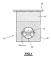
- FIG. 1 shows a cross-sectional view of an embankment, designated by the general reference numeral 10, in which a line 12 runs.
- the embankment 10 has two zones one of which, 14, constitutes a foundation for a roadway 16 and whose other zone, 18, constitutes a coating zone of the pipe 12.
- FIG. 1 also shows a compaction control apparatus of the coating zone 18, designated by the general reference numeral 20, and disposed in the pipe 12.
- This apparatus 20 controls the compaction of the embankment 10 by applying a force F on the inner surface of the wall of the pipe 12 so as to deform it, as shown in phantom in this figure, this deformation accompanied by a deformation consecutive to the coating zone 18 of the embankment.
- the device calculates the dry density of the embankment from the values of the applied force and the deformation of the embankment, as well as the nature of the latter, and then compares the dry density thus calculated with a dry density value corresponding to compaction optimum backfill.
- the device 20 for controlling the compaction of the embankment will now be described. 10 with reference to FIG.
- the apparatus 20 comprises, mounted on a frame 22, means 24 for applying a force on the wall of the pipe 12, and means 26 measuring the resulting deformation of the embankment by measuring the deformation D of the wall of the pipe.
- the means 24 for applying a force on the wall of the pipe comprise cylinders 28,30,32 and 34 arranged in pairs so that the cylinders 28 and 30 of one pairs exert, in operation, a force on the inner surface of the wall of the conduit 12 in a direction opposite to that exerted by the cylinders 32 and 34 of the other pair.
- the jacks of each pair are arranged on either side of the measuring means 26.
- They are for example constituted by air cylinders capable of exerting a pressure on the pipe in a range from 0 to 10 bars and are preferably double-acting cylinders, that is to say capable of being selectively controlled in tension or in thrust.
- the cylinders 28,30,32 and 34 are connected to a connecting member 36 of the jacks at a pressurized fluid supply source (not shown).
- a pressure sensor 38 is arranged in the fluid circuit each cylinder, between the connection member 36 and the latter, in to measure the force F applied to the wall of the pipe.
- the means 26 for measuring the deformation of the wall 12 of the pipe comprise two measuring rods 40 and 42 extending in the extension of one of the other.
- These measuring rods 40 and 42 are measuring rods of conventional type, appropriate for the intended use. They will not be described in detail by the after.
- the force F exerted on the pipe is applied by means of two skids side 48 and 50 each mounted on the active ends of a cylinder of one of the pairs.
- each pad 48 and 50 has two opposite end zones. 52 and 54 each having a cutout, such as 56, in which one end engages active actuator of a corresponding jack, and whose walls have orifices, such as 58, in which engage pins, such as 60, carried by the active end of each cylinder.
- FIG. 2 also shows that the active face of the median zone 62 of each shoe 48 and 50 is equipped with a roller 64, fixed for example by screwing, with interposition of a washer 66, by means of which the force provided by the jacks is applied to the driving 12.
- Each pad 48 and 50 and each roller 64, and the washer 66 which is associated, are pierced with coaxial orifices, such as 68, in which the active tip engages 44 measurement means, a spring 70 urging the frustoconical head 46 of the latter bearing against the inner face of the pad 48 and 50 corresponding.
- Each pad is further provided with wheels, such as 72, oscillating mounted on a support 76 being mounted on the end zones 52 and 54 of each pad.
- the control device which has just been described is completed by a central unit treatment unit (not shown) to which the measuring means are connected 26 as well as the pressure sensor 38.
- This central unit can be arranged on the frame where it can be placed at a distance, the outside of the pipe 12. It comprises, stored in memory of the calculation algorithms allowing the control of compaction of the embankment, as described in detail above.
- pads 78 and 80 equip the frame 22 on which the device rests in driving. Alternatively, these pads can be replaced by wheels.
- the apparatus 20 should be arranged in line 12.
- the central processing unit receives as input the value D of the consecutive displacement of the wall 12 of the pipe, which represents the value of the deformation of the embankment.
- the stiffness of the embankment is calculated from a calculation of the global stiffness R of driving, by establishing the ratio between the value F of the force applied and the value D of the resulting deformation.
- the optimum compaction being obtained when the value of the dry density reaches a maximum value, known under the name "Optimum Proctor", it is then simply necessary to compare the calculated dry density ⁇ d with a density value corresponding to the Optimum Proctor. , among a set of dry densities stored in memory in the central processing unit each corresponding to an optimum compaction of the embankment, for a type of material likely to enter the constitution of the embankment.
- the cylinders 28, 30, 32 and 34 are controlled by traction so as to exert a force exerted against the force exerted by the spring 70, to reposition the pads 48 and 50 in the waiting position, in which the wheels 72 are applied against the wall of the pipe 12.
- the device can then be easily moved to another location control.
- rollers 64 preferably have a disc shape of which the diameter is substantially equal to 1/10 of the diameter of the pipe to maintain a mechanical similarity with the models used for establishing the relationships mentioned previously allowing the calculation of the dry density.
Landscapes
- Life Sciences & Earth Sciences (AREA)
- Engineering & Computer Science (AREA)
- Mining & Mineral Resources (AREA)
- Geology (AREA)
- Physics & Mathematics (AREA)
- General Life Sciences & Earth Sciences (AREA)
- Geochemistry & Mineralogy (AREA)
- Environmental & Geological Engineering (AREA)
- Fluid Mechanics (AREA)
- Chemical & Material Sciences (AREA)
- Geophysics (AREA)
- Analytical Chemistry (AREA)
- Soil Sciences (AREA)
- Paleontology (AREA)
- Civil Engineering (AREA)
- General Engineering & Computer Science (AREA)
- Structural Engineering (AREA)
- Pit Excavations, Shoring, Fill Or Stabilisation Of Slopes (AREA)
- Investigating Strength Of Materials By Application Of Mechanical Stress (AREA)
- Investigation Of Foundation Soil And Reinforcement Of Foundation Soil By Compacting Or Drainage (AREA)
- Pipeline Systems (AREA)
Description
- la figure 1 est une vue schématique montrant une section en coupe transversale d'un remblai avant et après déformation,
- la figure 2 est une vue en perspective partiellement éclatée d'un appareil de contrôle du compactage du remblai de la figure 1.

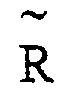
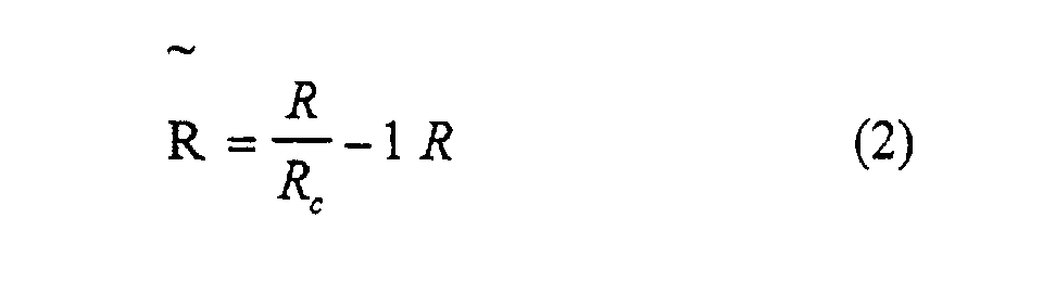
p' désigne la pression effective régnant dans le sol, à la profondeur de la conduite, et
A est un coefficient qui dépend de la nature du remblai.
Claims (11)
- Procédé de contrôle du compactage d'un remblai (10) d'enrobage d'une conduite (12), comportant les étapes consistant à:caractérisé en ce qu'il comprend en outre les étapes consistant àappliquer un effort (F) sur le remblai (10) de manière à obtenir une déformabilité (D) résultante de ce dernier,mesurer la déformation (D) du remblai,en ce que l'effort appliqué sur le remblai est appliqué par l'intermédiaire de la conduite (12), en exerçant un effort sur la surface interne de la conduite (12), etcalculer le module élastique du remblai (10) à partir de l'effort appliqué et de la déformation mesurée,déterminer la densité sèche du remblai (10) à partir du module élastique calculé et de la nature du remblai, etcomparer la densité sèche calculée avec une valeur de densité sèche correspondant à un compactage optimum du remblai,
en ce que la déformation du remblai est obtenue en mesurant la déformation de la paroi de la conduite (12). - Procédé selon la revendication 1, caractérisé en ce que l'étape d'application de l'effort sur le remblai (10) consiste à exercer un effort radial sur deux zones diamétralement opposées de la paroi de la conduite de manière à rendre sensiblement ovale sa section en coupe transversale.
- Procédé selon l'une des revendications 1 et 2, caractérisé en ce que l'étape de calcul du module élastique du remblai (10) comporte les étapes consistant à calculer la raideur du remblai, par calcul du rapport entre la valeur de l'effort (F) appliqué et la valeur de la déformation (D) résultante, et à calculer le module d'élasticité du remblai (10) à partir de la raideur calculée.
- Appareil de contrôle du compactage d'un remblai (10) d'enrobage d'une conduite (12), pour la mise en oeuvre d'un procédé de contrôle selon l'une quelconque des revendications 1 à 3, caractérisé en ce qu'il comporte des moyens (24) pour appliquer un effort sur la paroi de la conduite (12) de manière à la déformer, des moyens de mesure (26) de la déformation (D) résultante de la paroi de la conduite (12) et une unité centrale de traitement à laquelle sont raccordées lesdits moyens de mesure (26) et comportant des moyens de calcul de la densité sèche du remblai (10) à partir des valeurs de l'effort (F) appliqué et de la déformation (D) résultante de la paroi de la conduite (12), et des moyens de comparaison de la valeur de la densité sèche délivrée par les moyens de calcul avec une valeur de densité sèche correspondant à un compactage optimum du remblai (10).
- Appareil de contrôle selon la revendication 4, caractérisé en ce que les moyens (24) pour appliquer un effort sur la paroi de la conduite (12) comportent au moins un vérin (28,30,32,34), et en ce qu'il comporte en outre un capteur de pression (38) disposé dans le circuit fluidique d'alimentation du ou de chaque vérin et raccordé à l'unité centrale de traitement.
- Appareil de contrôle selon la revendication 5, caractérisé en ce qu'il comporte deux groupes d'au moins un vérin, le ou les vérins de l'un des groupes exerçant, en fonctionnement, un effort (F) selon un sens opposé à celui exercé par le ou les vérins de l'autre groupe.
- Appareil de contrôle selon la revendication 6, caractérisé en ce que chaque groupe de vérins comporte une paire de vérins disposés de part et d'autre des moyens de mesure de la déformation de la conduite.
- Appareil de contrôle selon la revendication 7, caractérisé en ce qu'il comporte deux patins (48,50) d'appui sur la surface interne de la paroi de la conduite (12) montés chacun sur les extrémités actives des vérins et de l'une des paires de vérins.
- Appareil de contrôle selon la revendication 8, caractérisé en ce que chaque patin (48,50) comporte deux zones d'extrémités opposées (52,54) munies chacune de moyens (58) de montage sur un vérin et une zone médiane (62) sur la face externe de laquelle est monté un galet (64) d'application de l'effort sur la conduite.
- Appareil de contrôle selon la revendication 9, caractérisé en ce que chaque galet et chaque patin (48,50) sont pourvus d'un orifice (68) pour le passage des moyens de mesure (26) de la déformation de la paroi de la conduite.
- Appareil de contrôle selon l'une des revendications 9 et 10, caractérisé en ce que chaque galet (64) a une forme de disque dont le diamètre est sensiblement égal à un dixième du diamètre de la conduite.
Applications Claiming Priority (2)
| Application Number | Priority Date | Filing Date | Title |
|---|---|---|---|
| FR9813694A FR2785310B1 (fr) | 1998-10-30 | 1998-10-30 | Procede et appareil de controle du compactage d'un remblai |
| FR9813694 | 1998-10-30 |
Publications (2)
| Publication Number | Publication Date |
|---|---|
| EP0997609A1 EP0997609A1 (fr) | 2000-05-03 |
| EP0997609B1 true EP0997609B1 (fr) | 2004-01-21 |
Family
ID=9532224
Family Applications (1)
| Application Number | Title | Priority Date | Filing Date |
|---|---|---|---|
| EP99402610A Expired - Lifetime EP0997609B1 (fr) | 1998-10-30 | 1999-10-21 | Procédé et appareil de contrôle du compactage d'un remblai |
Country Status (7)
| Country | Link |
|---|---|
| US (1) | US6389905B1 (fr) |
| EP (1) | EP0997609B1 (fr) |
| AR (1) | AR021027A1 (fr) |
| AT (1) | ATE258270T1 (fr) |
| DE (1) | DE69914281T2 (fr) |
| ES (1) | ES2215367T3 (fr) |
| FR (1) | FR2785310B1 (fr) |
Families Citing this family (3)
| Publication number | Priority date | Publication date | Assignee | Title |
|---|---|---|---|---|
| FR2871570B1 (fr) * | 2004-06-10 | 2006-09-29 | Paris Eaux Gestion | Dispositif de mesure de la rigidite d'une paroi et procede correspondant |
| US9264147B2 (en) * | 2010-03-24 | 2016-02-16 | Massachusetts Institute Of Technology | Method and apparatus for phase shift keyed optical communications |
| JP6909025B2 (ja) * | 2017-03-23 | 2021-07-28 | 大成建設株式会社 | 地盤改良体の測定装置および評価試験方法 |
Family Cites Families (10)
| Publication number | Priority date | Publication date | Assignee | Title |
|---|---|---|---|---|
| GB1246961A (en) * | 1967-10-04 | 1971-09-22 | Plessey Co Ltd | Improvements in or relating to the measurement of the wall thickness of tubular members |
| JPS59102009A (ja) * | 1982-12-02 | 1984-06-12 | Samu Denshi Kikai:Kk | 原位置における動的地盤剪断試験の方法 |
| US4650367A (en) * | 1983-11-30 | 1987-03-17 | Dietzler Daniel P | Internally reinforced extruded plastic pipe |
| JPS62165134A (ja) * | 1986-01-17 | 1987-07-21 | Taisei Corp | トンネル掘削における地山応力の測定方法 |
| US4733567A (en) * | 1986-06-23 | 1988-03-29 | Shosei Serata | Method and apparatus for measuring in situ earthen stresses and properties using a borehole probe |
| DE3712455C2 (de) * | 1987-04-11 | 1994-04-07 | Manfred Mueller | Verdichtungsprüfgerät |
| US5042595A (en) * | 1990-02-05 | 1991-08-27 | La Corporation De L'ecole Polytechnique | Method and device for in-situ determination of rheological properties of earth materials |
| US5105650A (en) * | 1990-03-08 | 1992-04-21 | Gas Research Institute | Monitoring compaction of backfill |
| JP3353181B2 (ja) * | 1994-06-27 | 2002-12-03 | 清水建設株式会社 | Ri法による測定溝の掘削装置および該掘削装置を用いた測定装置 |
| US5576485A (en) * | 1995-04-03 | 1996-11-19 | Serata; Shosei | Single fracture method and apparatus for simultaneous measurement of in-situ earthen stress state and material properties |
-
1998
- 1998-10-30 FR FR9813694A patent/FR2785310B1/fr not_active Expired - Fee Related
-
1999
- 1999-10-21 DE DE69914281T patent/DE69914281T2/de not_active Expired - Lifetime
- 1999-10-21 AT AT99402610T patent/ATE258270T1/de not_active IP Right Cessation
- 1999-10-21 ES ES99402610T patent/ES2215367T3/es not_active Expired - Lifetime
- 1999-10-21 EP EP99402610A patent/EP0997609B1/fr not_active Expired - Lifetime
- 1999-10-29 AR ARP990105479A patent/AR021027A1/es active IP Right Grant
- 1999-10-29 US US09/429,483 patent/US6389905B1/en not_active Expired - Fee Related
Also Published As
| Publication number | Publication date |
|---|---|
| AR021027A1 (es) | 2002-06-12 |
| FR2785310B1 (fr) | 2001-01-26 |
| DE69914281T2 (de) | 2004-11-25 |
| FR2785310A1 (fr) | 2000-05-05 |
| ES2215367T3 (es) | 2004-10-01 |
| DE69914281D1 (de) | 2004-02-26 |
| US6389905B1 (en) | 2002-05-21 |
| EP0997609A1 (fr) | 2000-05-03 |
| ATE258270T1 (de) | 2004-02-15 |
Similar Documents
| Publication | Publication Date | Title |
|---|---|---|
| FR2556478A1 (fr) | Procede et dispositif de mesures geophysiques dans un puits fore | |
| EP0337842B1 (fr) | Procédé et dispositif pour mesurer l'élasticité d'une couche superficielle, en particulier de la peau | |
| FR2614360A1 (fr) | Procede de mesure de la vitesse d'avancement d'un outil de forage | |
| FR2611804A1 (fr) | Procede de controle des operations de forage d'un puits | |
| EP0032648B1 (fr) | Pénétromètre statique | |
| EP0997609A1 (fr) | Procédé et appareil de contrôle du compactage d'un remblai | |
| EP0225827B1 (fr) | Cylindre à frette tournante | |
| FR2820501A1 (fr) | Mesure d'adherence entre une roue de vehicule et la chaussee | |
| EP2354781B1 (fr) | Dispositif de mesure du dégré de glissance d'un sol | |
| FR2780377A1 (fr) | Train de vehicule de transport, du type train suiveur de tunnelier | |
| EP0705941B1 (fr) | Pressiomètre à deux piézomètres | |
| CA2564373C (fr) | Dispositif d'impression d'une bande de papier conformee en un rouleau autour d'une bobine | |
| CH621866A5 (fr) | ||
| EP0269493A1 (fr) | Procédé et dispositif de contrôle de l'alignement des rouleaux d'une installation de coulée continue | |
| EP2221591B1 (fr) | Remorque dotée d'un dispositif de pesée embarqué, et procédé de pesée correspondant | |
| FR2843453A1 (fr) | Procede et dispositif de determination du diametre d'un objet sensiblement cylindrique | |
| FR2735229A1 (fr) | Dispositif de controle du dosage d'au moins un des constituants entrant dans la composition d'un produit de marquage routier | |
| FR2726082A1 (fr) | Dispositif de mesure des efforts de traction dans un cable de treuil | |
| FR2701774A1 (fr) | Procédé pour le réglage automatique de la position d'au moins un élément rectiligne fonctionnel d'une structure, moyens pour la mise en Óoeuvre du procédé et installations équipées de ces moyens. | |
| EP0010498B1 (fr) | Procédé et dispositif d'évaluation de la déformation d'une chaussée sous l'action d'une charge | |
| FR2750211A1 (fr) | Dispositif d'auscultation d'un conduit | |
| FR2520476A1 (fr) | Procede et dispositif pour l'obtention de donnees relatives a la position dans un plan vertical d'une conduite souple en cours d'enfouissement | |
| EP3299185B1 (fr) | Procédé et dispositif de détermination de la charge d'une roue d'un véhicule, et procédé et système de caractérisation d'un véhicule | |
| FR2656096A1 (fr) | Dispositif d'etalonnage de capteur. | |
| FR2648193A1 (fr) | Procede pour reguler une pression dans un circuit de travail a partir d'une pression de reference, dispositif pour la mise en oeuvre de ce procede, systeme de freinage et systeme limiteur d'effort comportant ce dispositif |
Legal Events
| Date | Code | Title | Description |
|---|---|---|---|
| PUAI | Public reference made under article 153(3) epc to a published international application that has entered the european phase |
Free format text: ORIGINAL CODE: 0009012 |
|
| AK | Designated contracting states |
Kind code of ref document: A1 Designated state(s): AT BE CH CY DE DK ES FI FR GB GR IE IT LI LU MC NL PT SE |
|
| AX | Request for extension of the european patent |
Free format text: AL;LT;LV;MK;RO;SI |
|
| 17P | Request for examination filed |
Effective date: 20000503 |
|
| AKX | Designation fees paid |
Free format text: AT BE CH CY DE DK ES FI FR GB GR IE IT LI LU MC NL PT SE |
|
| 17Q | First examination report despatched |
Effective date: 20020715 |
|
| GRAH | Despatch of communication of intention to grant a patent |
Free format text: ORIGINAL CODE: EPIDOS IGRA |
|
| GRAS | Grant fee paid |
Free format text: ORIGINAL CODE: EPIDOSNIGR3 |
|
| GRAA | (expected) grant |
Free format text: ORIGINAL CODE: 0009210 |
|
| AK | Designated contracting states |
Kind code of ref document: B1 Designated state(s): AT BE CH CY DE DK ES FI FR GB GR IE IT LI LU MC NL PT SE |
|
| PG25 | Lapsed in a contracting state [announced via postgrant information from national office to epo] |
Ref country code: NL Free format text: LAPSE BECAUSE OF FAILURE TO SUBMIT A TRANSLATION OF THE DESCRIPTION OR TO PAY THE FEE WITHIN THE PRESCRIBED TIME-LIMIT Effective date: 20040121 Ref country code: IT Free format text: LAPSE BECAUSE OF FAILURE TO SUBMIT A TRANSLATION OF THE DESCRIPTION OR TO PAY THE FEE WITHIN THE PRESCRIBED TIME-LIMIT;WARNING: LAPSES OF ITALIAN PATENTS WITH EFFECTIVE DATE BEFORE 2007 MAY HAVE OCCURRED AT ANY TIME BEFORE 2007. THE CORRECT EFFECTIVE DATE MAY BE DIFFERENT FROM THE ONE RECORDED. Effective date: 20040121 Ref country code: IE Free format text: LAPSE BECAUSE OF FAILURE TO SUBMIT A TRANSLATION OF THE DESCRIPTION OR TO PAY THE FEE WITHIN THE PRESCRIBED TIME-LIMIT Effective date: 20040121 Ref country code: FI Free format text: LAPSE BECAUSE OF FAILURE TO SUBMIT A TRANSLATION OF THE DESCRIPTION OR TO PAY THE FEE WITHIN THE PRESCRIBED TIME-LIMIT Effective date: 20040121 Ref country code: CY Free format text: LAPSE BECAUSE OF FAILURE TO SUBMIT A TRANSLATION OF THE DESCRIPTION OR TO PAY THE FEE WITHIN THE PRESCRIBED TIME-LIMIT Effective date: 20040121 Ref country code: AT Free format text: LAPSE BECAUSE OF FAILURE TO SUBMIT A TRANSLATION OF THE DESCRIPTION OR TO PAY THE FEE WITHIN THE PRESCRIBED TIME-LIMIT Effective date: 20040121 |
|
| REG | Reference to a national code |
Ref country code: GB Ref legal event code: FG4D Free format text: NOT ENGLISH |
|
| REG | Reference to a national code |
Ref country code: CH Ref legal event code: EP |
|
| REG | Reference to a national code |
Ref country code: IE Ref legal event code: FG4D Free format text: FRENCH |
|
| REF | Corresponds to: |
Ref document number: 69914281 Country of ref document: DE Date of ref document: 20040226 Kind code of ref document: P |
|
| PG25 | Lapsed in a contracting state [announced via postgrant information from national office to epo] |
Ref country code: SE Free format text: LAPSE BECAUSE OF FAILURE TO SUBMIT A TRANSLATION OF THE DESCRIPTION OR TO PAY THE FEE WITHIN THE PRESCRIBED TIME-LIMIT Effective date: 20040421 Ref country code: GR Free format text: LAPSE BECAUSE OF FAILURE TO SUBMIT A TRANSLATION OF THE DESCRIPTION OR TO PAY THE FEE WITHIN THE PRESCRIBED TIME-LIMIT Effective date: 20040421 Ref country code: DK Free format text: LAPSE BECAUSE OF FAILURE TO SUBMIT A TRANSLATION OF THE DESCRIPTION OR TO PAY THE FEE WITHIN THE PRESCRIBED TIME-LIMIT Effective date: 20040421 |
|
| GBT | Gb: translation of ep patent filed (gb section 77(6)(a)/1977) |
Effective date: 20040520 |
|
| NLV1 | Nl: lapsed or annulled due to failure to fulfill the requirements of art. 29p and 29m of the patents act | ||
| REG | Reference to a national code |
Ref country code: IE Ref legal event code: FD4D |
|
| REG | Reference to a national code |
Ref country code: ES Ref legal event code: FG2A Ref document number: 2215367 Country of ref document: ES Kind code of ref document: T3 |
|
| PLBE | No opposition filed within time limit |
Free format text: ORIGINAL CODE: 0009261 |
|
| STAA | Information on the status of an ep patent application or granted ep patent |
Free format text: STATUS: NO OPPOSITION FILED WITHIN TIME LIMIT |
|
| 26N | No opposition filed |
Effective date: 20041022 |
|
| PG25 | Lapsed in a contracting state [announced via postgrant information from national office to epo] |
Ref country code: PT Free format text: LAPSE BECAUSE OF NON-PAYMENT OF DUE FEES Effective date: 20040621 |
|
| PGFP | Annual fee paid to national office [announced via postgrant information from national office to epo] |
Ref country code: MC Payment date: 20091027 Year of fee payment: 11 Ref country code: LU Payment date: 20091026 Year of fee payment: 11 |
|
| REG | Reference to a national code |
Ref country code: FR Ref legal event code: TP |
|
| PG25 | Lapsed in a contracting state [announced via postgrant information from national office to epo] |
Ref country code: MC Free format text: LAPSE BECAUSE OF NON-PAYMENT OF DUE FEES Effective date: 20101031 |
|
| REG | Reference to a national code |
Ref country code: DE Ref legal event code: R082 Ref document number: 69914281 Country of ref document: DE Representative=s name: KADOR & PARTNER, DE |
|
| REG | Reference to a national code |
Ref country code: DE Ref legal event code: R082 Ref document number: 69914281 Country of ref document: DE Representative=s name: KADOR & PARTNER PART MBB PATENTANWAELTE, DE Effective date: 20120207 Ref country code: DE Ref legal event code: R082 Ref document number: 69914281 Country of ref document: DE Representative=s name: KADOR & PARTNER, DE Effective date: 20120207 Ref country code: DE Ref legal event code: R081 Ref document number: 69914281 Country of ref document: DE Owner name: EAU DE PARIS, FR Free format text: FORMER OWNER: SOCIETE ANONYME DE GESTION DES EAUX DE PARIS (SAGEP), PARIS, FR Effective date: 20120207 |
|
| REG | Reference to a national code |
Ref country code: CH Ref legal event code: PFUS Owner name: EAU DE PARIS, FR Free format text: FORMER OWNER: SOCIETE ANONYME DE GESTION DES EAUX DE PARIS (SAGEP), FR Ref country code: CH Ref legal event code: NV Representative=s name: E-PATENT S.A. |
|
| REG | Reference to a national code |
Ref country code: ES Ref legal event code: PC2A Owner name: EAU DE PARIS Effective date: 20120906 |
|
| PG25 | Lapsed in a contracting state [announced via postgrant information from national office to epo] |
Ref country code: LU Free format text: LAPSE BECAUSE OF NON-PAYMENT OF DUE FEES Effective date: 20101021 |
|
| REG | Reference to a national code |
Ref country code: FR Ref legal event code: PLFP Year of fee payment: 18 |
|
| PGFP | Annual fee paid to national office [announced via postgrant information from national office to epo] |
Ref country code: FR Payment date: 20160929 Year of fee payment: 18 |
|
| REG | Reference to a national code |
Ref country code: FR Ref legal event code: ST Effective date: 20180629 |
|
| PG25 | Lapsed in a contracting state [announced via postgrant information from national office to epo] |
Ref country code: FR Free format text: LAPSE BECAUSE OF NON-PAYMENT OF DUE FEES Effective date: 20171031 |
|
| PGFP | Annual fee paid to national office [announced via postgrant information from national office to epo] |
Ref country code: BE Payment date: 20180921 Year of fee payment: 20 Ref country code: GB Payment date: 20180925 Year of fee payment: 20 Ref country code: CH Payment date: 20180925 Year of fee payment: 20 |
|
| PGFP | Annual fee paid to national office [announced via postgrant information from national office to epo] |
Ref country code: DE Payment date: 20180819 Year of fee payment: 20 |
|
| PGFP | Annual fee paid to national office [announced via postgrant information from national office to epo] |
Ref country code: ES Payment date: 20181105 Year of fee payment: 20 |
|
| REG | Reference to a national code |
Ref country code: DE Ref legal event code: R071 Ref document number: 69914281 Country of ref document: DE |
|
| REG | Reference to a national code |
Ref country code: CH Ref legal event code: PL |
|
| REG | Reference to a national code |
Ref country code: GB Ref legal event code: PE20 Expiry date: 20191020 |
|
| REG | Reference to a national code |
Ref country code: BE Ref legal event code: MK Effective date: 20191021 |
|
| PG25 | Lapsed in a contracting state [announced via postgrant information from national office to epo] |
Ref country code: GB Free format text: LAPSE BECAUSE OF EXPIRATION OF PROTECTION Effective date: 20191020 |
|
| REG | Reference to a national code |
Ref country code: ES Ref legal event code: FD2A Effective date: 20201110 |
|
| PG25 | Lapsed in a contracting state [announced via postgrant information from national office to epo] |
Ref country code: ES Free format text: LAPSE BECAUSE OF EXPIRATION OF PROTECTION Effective date: 20191022 |