EP0997629B1 - Batiment pour un moteur à plusieurs cylindres - Google Patents
Batiment pour un moteur à plusieurs cylindres Download PDFInfo
- Publication number
- EP0997629B1 EP0997629B1 EP99118729A EP99118729A EP0997629B1 EP 0997629 B1 EP0997629 B1 EP 0997629B1 EP 99118729 A EP99118729 A EP 99118729A EP 99118729 A EP99118729 A EP 99118729A EP 0997629 B1 EP0997629 B1 EP 0997629B1
- Authority
- EP
- European Patent Office
- Prior art keywords
- breathing
- holes
- crankcase
- oilway
- center
- Prior art date
- Legal status (The legal status is an assumption and is not a legal conclusion. Google has not performed a legal analysis and makes no representation as to the accuracy of the status listed.)
- Expired - Lifetime
Links
Images

Classifications
-
- F—MECHANICAL ENGINEERING; LIGHTING; HEATING; WEAPONS; BLASTING
- F02—COMBUSTION ENGINES; HOT-GAS OR COMBUSTION-PRODUCT ENGINE PLANTS
- F02F—CYLINDERS, PISTONS OR CASINGS, FOR COMBUSTION ENGINES; ARRANGEMENTS OF SEALINGS IN COMBUSTION ENGINES
- F02F7/00—Casings, e.g. crankcases
-
- F—MECHANICAL ENGINEERING; LIGHTING; HEATING; WEAPONS; BLASTING
- F01—MACHINES OR ENGINES IN GENERAL; ENGINE PLANTS IN GENERAL; STEAM ENGINES
- F01M—LUBRICATING OF MACHINES OR ENGINES IN GENERAL; LUBRICATING INTERNAL COMBUSTION ENGINES; CRANKCASE VENTILATING
- F01M11/00—Component parts, details or accessories, not provided for in, or of interest apart from, groups F01M1/00 - F01M9/00
- F01M11/02—Arrangements of lubricant conduits
Definitions
- the present invention relates to a crankcase for a multiple cylinder engine, and more particularly to a structure for providing breathing holes having a sufficient hole diameter in journal walls of the crankcase.
- breathing holes are formed opening into journal walls. These sort of breathing holes for each journal wall are formed at one time by machine processing in a direction parallel to a central axis of the crankshaft with respect to a cast cylinder block, and this results in each breathing hole being arranged coaxially (see, for example, Japanese patent laid-open No. Hei. 10-77905 or document DE 37 27 670 A).
- oilways and bolt fastening section are provided in the journal walls, and since these are integrally formed at the time of casting the cylinder block.
- the hole diameter must be made small in order to avoid the oilways and bolt fastening sections, which makes it difficult to make the hole diameters large enough to reduce friction loss.
- the object of the invention of this application is to solve this type of problem.
- a first invention relating to a crankcase of a multiple cylinder engine of the present application is a crankcase for a multiple cylinder engine having crank chambers for each cylinder of the multiple cylinder engine arranged along the axial direction of a crankshaft, and provided with breathing holes communicating between the crank chambers and respective journal walls supporting the crankshaft and constituting wall sections of each crank chamber, wherein the breathing holes are lined up along the crankshaft, and at least one of the breathing holes has a center different from centers of the other breathing holes.
- breathing holes are provided for each journal wall, the number of breathing holes is the same as the number of journal walls, and it is sufficient if at least one of these breathing holes has a center different from the others. Accordingly, various combinations of breathing holes are included, from a combination where only the center position of one breathing hole is different, to a combination where the center positions of all the breathing holes are different.
- a second invention is basically the first invention, in which the journal wall in which the breathing hole having a different center is provided has an oilway, and is formed at a position avoiding this oilway.
- a third invention is basically the first or second invention in which the journal wall in which the breathing hole having a different center is provided has a bolt fastening section, and is formed at a position avoiding this bolt fastening section.
- each journal wall since at least one of a plurality of breathing holes that have been provided in each journal wall has a center different from all the others, it is possible to vary the position of the breathing holes according to the structure of the journal wall, with the result that the diameter of the breathing holes can be made sufficiently large and it is possible to ensure an opening area sufficient to reduce friction loss.
- the breathing hole is formed avoiding the oilway, it is possible to form the breathing hole having a sufficiently large diameter without complicating the oilway.
- the breathing hole in the case where a bolt fastening section is provided in the journal wall, and the breathing hole is formed avoiding the bolt fastening sections, it is possible to form the breathing hole having a sufficiently large diameter without shortening the length of the bolts.
- Fig. 1 is a cross sectional drawing of a cylinder section to which the embodiment relates
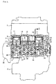
- Fig. 2 is a drawing showing a section through a crank chamber section of this engine
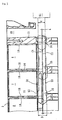
- Fig. 3 is a drawing showing a method of manufacturing breathing holes.
- FIG. 2 This engine is a water-cooled in-line 4-cylinder engine.
- reference numeral 1 is a cylinder head
- 2 is a crankcase
- 3 is a cylinder section
- 4 is a lower case
- 5 is a transmission.
- the crankcase 2 is divided into two parts, namely an upper case, that is formed integrally with the cylinder section 3, and a lower case 4.
- crankshaft 10 is connected to pistons 11 sliding within each of the cylinders 6 - 9 via connecting rods 12, and is supported by journal walls 13 - 17.
- the journal walls 13 - 17 each define cylinders 6 - 9 inside the crankcase 2 and crank chambers 20 - 23 corresponding to these cylinders. Breathing holes 24 - 28 are also formed in each of the journal walls 13 - 17.
- the breathing holes 24 - 28 are respectively formed one each in the journal walls 13 - 17, with the same diameter, and are aligned along the axial direction of the crankshaft 10 communicating with each of the crank chambers 20 - 23.
- reference numeral 30 is an ACG cover
- reference numeral 31 is a cam shaft drive sprocket
- reference numeral 32 is a cam chain
- reference numeral 33 is a cam chain chamber
- reference numerals 34 - 38 are journal walls for the crankshaft 10 at the lower case 4 side.
- Fig. 1 shows a journal wall 14, and a semicircular cavity 41 for housing the crankshaft 10 via a metal bearing 19 is formed in a lower surface 40 of the journal wall 14.An oilway 42 is also formed in the circumference of this cavity 41.
- the oilway 42 extends upwards and leads to an attachment hole 43 for a pressure switch (omitted from the drawing) formed in a side of the journal wall 14, extends from there through a side hole to the journal wall 13 (Fig. 2), bends at a thickened part of the journal wall 13 and connects to a separate oilway 44 that extends upwards.
- a pair of bolt attachment screw holes 45 are formed leading upwards from the lower surface 40 on either side of the cavity 41. These bolt holes 45 correspond to the bolt fastening sections of the present application and bolts, not shown, for joining the lower case 4 side are screwed into the holes from the side shown at the bottom of the drawing.
- a breathing hole 25 is formed at a position leading away from the oilway 42 and the screw holes 45.
- the diameter of this breathing hole 25 is sufficiently large to avoid friction loss, and is offset from a center position of a breathing hole 24 formed in the adjacent journal wall 13.
- the center C1 of the breathing hole 24 is offset by ⁇ c from the center C2 of the breathing hole 25, and is eccentric by ⁇ c from the oilway 42, if the center of the breathing hole 24 for the journal wall 13 in which the oilway 42 and screw holes 45 are provided is used as a reference.
- the center of the breathing hole 24 is also positioned a sufficient distance away from the tips of the screw holes 45.
- these breathing holes 24 - 27 are formed by punching the cast cylinder section 3 from a direction parallel to the axial direction of the crankshaft 10, using a suitable fabrication system, such as an NC machine tool using a tool 50. At the time the cylinder section 3 is cast, the cavity 41, oilway 42 and screw holes 45 before being tapped, etc. are integrally formed.
- the tool 50 comprises a blade section 52 having an outer diameter D and provided at a tip, and a shaft section 53 having an outer diameter d smaller than the outer diameter D.
- the diameter D of the blade section 52 is approximately equal to the inner diameter of each of the breathing holes 24 - 27, while the diameter d of the shaft section 53 is determined from the maximum offset amount of the breathing holes.
- the breathing hole 24 is punched on the center C1 using the tool 50, the blade section 52 passes through the journal wall 13, the shaft section 53 moves from there to the center C2, and the breathing hole 25 is formed in the journal wall 14.
- the amount of movement a of the centers at this time is equivalent to an offset amount between the breathing hole 24 and the breathing hole 25 in a vertical direction in the drawing.
- the shaft section 53 is again moved by only a distance b, and then the breathing hole 26 for the journal wall 15 is punched.
- the breathing hole 26 is formed having the center C3 offset by only the offset amount b in a vertical direction from the center C1 of the breathing hole 24.
- the breathing hole 27 and subsequent holes are punched in the same way.
- the offset amounts a and b in Fig. 3 are offset amounts in the vertical direction of the drawings.
- the breathing holes are also appropriately offset in the lateral direction of Fig. 1 equal to the above described ⁇ c. This offset amount is appropriately determined taking into consideration avoidance of the oilway 42 and the screw holes 45, etc. and the structure of each of the journal walls 13 - 17.
- the outer diameter d of the shaft section 53 is determined with one of the breathing holes, for example the above described breathing hole 24, as a reference, so that a difference between the outer diameter D of the blade section 52 and the outer diameter d of the shaft section 53 is approximately at least double an offset amount by which some breathing hole is most offset from the reference breathing hole, i.e. a maximum offset amount.
- the oilway 42 and the screw holes 45 are provided in the journal wall 14.
- the breathing hole 25 is offset with respect to a breathing hole of another journal wall, for example the breathing hole 24 of the adjacent journal wall 13, so that the breathing hole 25 is formed away from the oilway 42 and the screw holes 45.
- the breathing holes 24, and 26 - 28 for the other journal walls 13 and 15 - 17 are also the same and can be formed at the most convenient positions, and at this time if it is necessary for the oilway and screw holes to avoid other parts, they can be formed escaping with the same diameter.
- One journal wall 13 of an in-line four cylinder engine is provided with an oilway 42 and screw holes 45, being bolt fastening sections.
- a center C1 of a breathing hole 24 punched in this journal wall 13 avoids the oilway 42 and screw holes 45 by being offset by an amount ⁇ c with respect to a center C2 of a breathing hole 25 formed in an adjacent journal wall.
Landscapes
- Engineering & Computer Science (AREA)
- Mechanical Engineering (AREA)
- General Engineering & Computer Science (AREA)
- Chemical & Material Sciences (AREA)
- Combustion & Propulsion (AREA)
- Cylinder Crankcases Of Internal Combustion Engines (AREA)
- Shafts, Cranks, Connecting Bars, And Related Bearings (AREA)
- Lubrication Details And Ventilation Of Internal Combustion Engines (AREA)
Claims (3)
- Carter de vilebrequin (2) pour un moteur à plusieurs cylindres ayant des chambres pour vilebrequin (20 à 23) pour chaque cylindre (6 à 9) du moteur à plusieurs cylindres agencées le long de la direction axiale d'un vilebrequin (10), et muni d'une pluralité de trous de respiration (24 à 28) communiquant entre les chambres pour vilebrequin (20 à 23) et des parois de tourillonnement respectives (13 à 17) supportant le vilebrequin (10) et constituant des tronçons de paroi de chaque chambre pour vilebrequin (20 à 23), les trous de respiration (24 à 28) étant alignés dans la direction axiale du vilebrequin (10),
caractérisé en ce qu'au moins un des trous de respiration (24 à 28) a un axe décalé par rapport aux axes des autres trous de respiration (24 à 28) dans une direction orthogonale à la direction axiale du vilebrequin (10), afin d'éviter des parties essentielles (42, 45) du carter de vilebrequin (2). - Carter de vilebrequin (2) pour un moteur à plusieurs cylindres selon la revendication 1, dans lequel la paroi de tourillonnement (14) dans laquelle est agencé le trou de respiration (25) ayant l'axe différent (C2) comporte un passage d'huile (42), et le trou de respiration (25) ayant l'axe décalé (C2) est formé dans une position évitant ce passage d'huile (42).
- Carter de vilebrequin (2) pour un moteur à plusieurs cylindres selon la revendication 1 ou 2, dans lequel la paroi de tourillonnement (14) dans laquelle est agencé le trou de respiration (25) ayant l'axe décalé (C2), comporte un tronçon de fixation de boulon (45), et est formé dans une position évitant ce tronçon de fixation de boulon (45).
Applications Claiming Priority (2)
| Application Number | Priority Date | Filing Date | Title |
|---|---|---|---|
| JP32601898 | 1998-10-31 | ||
| JP10326018A JP2000136752A (ja) | 1998-10-31 | 1998-10-31 | 多気筒エンジンのクランクケース |
Publications (3)
| Publication Number | Publication Date |
|---|---|
| EP0997629A2 EP0997629A2 (fr) | 2000-05-03 |
| EP0997629A3 EP0997629A3 (fr) | 2001-01-24 |
| EP0997629B1 true EP0997629B1 (fr) | 2005-02-09 |
Family
ID=18183184
Family Applications (1)
| Application Number | Title | Priority Date | Filing Date |
|---|---|---|---|
| EP99118729A Expired - Lifetime EP0997629B1 (fr) | 1998-10-31 | 1999-09-22 | Batiment pour un moteur à plusieurs cylindres |
Country Status (4)
| Country | Link |
|---|---|
| US (1) | US6244238B1 (fr) |
| EP (1) | EP0997629B1 (fr) |
| JP (1) | JP2000136752A (fr) |
| DE (1) | DE69923643T2 (fr) |
Families Citing this family (6)
| Publication number | Priority date | Publication date | Assignee | Title |
|---|---|---|---|---|
| US6827057B2 (en) * | 2001-03-15 | 2004-12-07 | Ralph E. Dawson | Angle bored cylinder engine |
| JP2003074408A (ja) * | 2001-08-31 | 2003-03-12 | Honda Motor Co Ltd | 複数気筒エンジンのシリンダブロック |
| JP2005291089A (ja) | 2004-03-31 | 2005-10-20 | Toyota Motor Corp | エンジンのシリンダブロック |
| JP4640262B2 (ja) | 2006-05-31 | 2011-03-02 | 日産自動車株式会社 | 多気筒エンジンのクランクケース |
| DE102006028801B4 (de) * | 2006-06-23 | 2017-10-12 | Bayerische Motoren Werke Aktiengesellschaft | Kurbelgehäuse mit einer Ventilationsbohrung |
| JP5548486B2 (ja) * | 2010-03-04 | 2014-07-16 | 本田技研工業株式会社 | 多気筒エンジン |
Family Cites Families (12)
| Publication number | Priority date | Publication date | Assignee | Title |
|---|---|---|---|---|
| KR830009360A (ko) * | 1981-02-27 | 1983-12-19 | 에르스베트 루드빅 | 왕복동 피스톤식 내연기관용의 케이싱 블록 |
| DE3465758D1 (en) * | 1983-12-02 | 1987-10-08 | Austin Rover Group | Internal combustion engine |
| JP2527350B2 (ja) * | 1987-02-25 | 1996-08-21 | 富士写真フイルム株式会社 | ベクトル量子化による画像デ―タの圧縮および再構成装置 |
| DE3727670A1 (de) * | 1987-08-19 | 1989-03-02 | Daimler Benz Ag | Gehaeuseblock fuer hubkolben-brennkraftmaschine |
| AT398608B (de) * | 1987-09-22 | 1995-01-25 | Avl Verbrennungskraft Messtech | Kurbelgehäuse |
| DE4231284A1 (de) * | 1992-09-18 | 1994-03-24 | Bruehl Eisenwerk | Zylinderblock für eine Brennkraftmaschine |
| US6076495A (en) * | 1996-04-08 | 2000-06-20 | Sanshin Kogyo Kabushiki Kaisha | Bearing arrangement for vertical engine |
| DE19628110C1 (de) * | 1996-07-12 | 1997-10-02 | Daimler Benz Ag | Kurbelgehäuse für eine Hubkolbenmaschine |
| JP3614992B2 (ja) | 1996-08-30 | 2005-01-26 | ヤマハ発動機株式会社 | 自動二輪車用エンジンユニット |
| JP3339330B2 (ja) * | 1996-10-18 | 2002-10-28 | トヨタ自動車株式会社 | 内燃機関のシリンダブロック |
| US5829406A (en) * | 1997-07-31 | 1998-11-03 | General Motors Corporation | Balancing crankcase pressure |
| US5852992A (en) * | 1997-11-24 | 1998-12-29 | Ford Global Technologies, Inc. | Internal combuston engine having separated cylinder head oil drains and crankcase ventilation passages |
-
1998
- 1998-10-31 JP JP10326018A patent/JP2000136752A/ja active Pending
-
1999
- 1999-09-22 DE DE69923643T patent/DE69923643T2/de not_active Expired - Lifetime
- 1999-09-22 EP EP99118729A patent/EP0997629B1/fr not_active Expired - Lifetime
- 1999-10-29 US US09/429,084 patent/US6244238B1/en not_active Expired - Fee Related
Also Published As
| Publication number | Publication date |
|---|---|
| EP0997629A3 (fr) | 2001-01-24 |
| JP2000136752A (ja) | 2000-05-16 |
| DE69923643T2 (de) | 2005-07-07 |
| US6244238B1 (en) | 2001-06-12 |
| DE69923643D1 (de) | 2005-03-17 |
| EP0997629A2 (fr) | 2000-05-03 |
Similar Documents
| Publication | Publication Date | Title |
|---|---|---|
| RU2208188C2 (ru) | Способ изготовления шатуна для поршневых машин, в частности для компрессоров | |
| CN1115475C (zh) | 活塞 | |
| RU2101511C1 (ru) | Устройство для преобразования возвратно-поступательного движения во вращательное и наоборот и устройство с возвратно-поступательно движущимися частями | |
| EP0997629B1 (fr) | Batiment pour un moteur à plusieurs cylindres | |
| US6012423A (en) | Hypocycloidal crank mechanism for piston engines, engines especially for opposed-cylinder internal combustion engines | |
| KR100262232B1 (ko) | 다실린더 2 행정 사이클 왕복 내연기관 | |
| US4465029A (en) | Reinforced crankcase for an internal combustion engine with a balancer shaft | |
| EP1865183B1 (fr) | Procédé pour la fabrication d'un bloc moteur | |
| JP2000205238A (ja) | 鍛造クランクシャフト | |
| JPH04224340A (ja) | 支承装置 | |
| US5025673A (en) | Crank case of engine for motor-bicycle | |
| US7509934B2 (en) | Device for guiding media in a cylinder block and crankcase | |
| JPH10122042A (ja) | 内燃機関のシリンダブロック | |
| US5598815A (en) | Roller lever of a casting machine | |
| JPH0724691Y2 (ja) | バランサ軸 | |
| JP3599178B2 (ja) | V型多気筒エンジン | |
| KR0140611B1 (ko) | 실린더 블록의 메인 베어링 캡 제작 방법 | |
| JPH09310640A (ja) | 内燃機関のピストン | |
| JPH0623693Y2 (ja) | エンジンのスラストプレ−ト潤滑構造 | |
| JPH108931A (ja) | エンジンのオイル通路形成方法 | |
| JP2000110663A (ja) | 多気筒エンジンのクランクケース | |
| JPH11270401A (ja) | 並列2気筒エンジン | |
| JPH054599Y2 (fr) | ||
| JPH0318761Y2 (fr) | ||
| KR19980084922A (ko) | 크랭크 샤프트용 베어링 캡의 조립구조 |
Legal Events
| Date | Code | Title | Description |
|---|---|---|---|
| PUAI | Public reference made under article 153(3) epc to a published international application that has entered the european phase |
Free format text: ORIGINAL CODE: 0009012 |
|
| AK | Designated contracting states |
Kind code of ref document: A2 Designated state(s): DE GB IT |
|
| AX | Request for extension of the european patent |
Free format text: AL;LT;LV;MK;RO;SI |
|
| PUAL | Search report despatched |
Free format text: ORIGINAL CODE: 0009013 |
|
| AK | Designated contracting states |
Kind code of ref document: A3 Designated state(s): AT BE CH CY DE DK ES FI FR GB GR IE IT LI LU MC NL PT SE |
|
| AX | Request for extension of the european patent |
Free format text: AL;LT;LV;MK;RO;SI |
|
| 17P | Request for examination filed |
Effective date: 20010212 |
|
| AKX | Designation fees paid |
Free format text: DE GB IT |
|
| 17Q | First examination report despatched |
Effective date: 20031202 |
|
| GRAP | Despatch of communication of intention to grant a patent |
Free format text: ORIGINAL CODE: EPIDOSNIGR1 |
|
| RIN1 | Information on inventor provided before grant (corrected) |
Inventor name: TANAKA, YOICHIC/O HONDA GIKEN KOGYO K. K. Inventor name: TAKAHASHI, KATSUNORI |
|
| GRAS | Grant fee paid |
Free format text: ORIGINAL CODE: EPIDOSNIGR3 |
|
| GRAA | (expected) grant |
Free format text: ORIGINAL CODE: 0009210 |
|
| AK | Designated contracting states |
Kind code of ref document: B1 Designated state(s): DE GB IT |
|
| REG | Reference to a national code |
Ref country code: GB Ref legal event code: FG4D |
|
| REF | Corresponds to: |
Ref document number: 69923643 Country of ref document: DE Date of ref document: 20050317 Kind code of ref document: P |
|
| PLBE | No opposition filed within time limit |
Free format text: ORIGINAL CODE: 0009261 |
|
| STAA | Information on the status of an ep patent application or granted ep patent |
Free format text: STATUS: NO OPPOSITION FILED WITHIN TIME LIMIT |
|
| 26N | No opposition filed |
Effective date: 20051110 |
|
| PGFP | Annual fee paid to national office [announced via postgrant information from national office to epo] |
Ref country code: GB Payment date: 20080924 Year of fee payment: 10 |
|
| GBPC | Gb: european patent ceased through non-payment of renewal fee |
Effective date: 20090922 |
|
| PG25 | Lapsed in a contracting state [announced via postgrant information from national office to epo] |
Ref country code: GB Free format text: LAPSE BECAUSE OF NON-PAYMENT OF DUE FEES Effective date: 20090922 |
|
| PGFP | Annual fee paid to national office [announced via postgrant information from national office to epo] |
Ref country code: IT Payment date: 20110921 Year of fee payment: 13 |
|
| PGFP | Annual fee paid to national office [announced via postgrant information from national office to epo] |
Ref country code: DE Payment date: 20120919 Year of fee payment: 14 |
|
| PG25 | Lapsed in a contracting state [announced via postgrant information from national office to epo] |
Ref country code: IT Free format text: LAPSE BECAUSE OF NON-PAYMENT OF DUE FEES Effective date: 20120922 |
|
| REG | Reference to a national code |
Ref country code: DE Ref legal event code: R119 Ref document number: 69923643 Country of ref document: DE Effective date: 20140401 |
|
| PG25 | Lapsed in a contracting state [announced via postgrant information from national office to epo] |
Ref country code: DE Free format text: LAPSE BECAUSE OF NON-PAYMENT OF DUE FEES Effective date: 20140401 |