EP0997635A2 - Method for testing a throttle point, especially a throttle point of an injector - Google Patents
Method for testing a throttle point, especially a throttle point of an injector Download PDFInfo
- Publication number
- EP0997635A2 EP0997635A2 EP99121321A EP99121321A EP0997635A2 EP 0997635 A2 EP0997635 A2 EP 0997635A2 EP 99121321 A EP99121321 A EP 99121321A EP 99121321 A EP99121321 A EP 99121321A EP 0997635 A2 EP0997635 A2 EP 0997635A2
- Authority
- EP
- European Patent Office
- Prior art keywords
- determined
- pressure level
- parameter
- detected
- operating point
- Prior art date
- Legal status (The legal status is an assumption and is not a legal conclusion. Google has not performed a legal analysis and makes no representation as to the accuracy of the status listed.)
- Withdrawn
Links
Images


Classifications
-
- F—MECHANICAL ENGINEERING; LIGHTING; HEATING; WEAPONS; BLASTING
- F02—COMBUSTION ENGINES; HOT-GAS OR COMBUSTION-PRODUCT ENGINE PLANTS
- F02M—SUPPLYING COMBUSTION ENGINES IN GENERAL WITH COMBUSTIBLE MIXTURES OR CONSTITUENTS THEREOF
- F02M65/00—Testing fuel-injection apparatus, e.g. testing injection timing ; Cleaning of fuel-injection apparatus
Definitions
- the invention relates to a method for testing a throttle point, in particular the Throttle point of an injector on a test bench.
- the injector is used by one Pump applied with a first constant pressure level on the primary side. In addition becomes the volume flow of the hydraulic pressure medium provided by the pump detected.
- the invention lies in that The task is to develop this further.
- a first solution according to the invention is that a first and another Operating points are determined, the first operating point being a significant one Characteristic field determined.
- the other operating points become the characteristic field assigned which is a range of permissible and non-permissible operating points having. Then, based on the position of the other operating points in the characteristic field a positive or negative test result can be detected.
- both the first and the further Operating points are largely determined by a first and second parameter.
- the first parameter is calculated from the first pressure level on the primary side and a second, predeterminable secondary pressure level of the injector.
- the second The parameter is largely determined by the measured volume flow and the first and second Pressure level determined.
- the other operating points largely determined by the increase in the second pressure level.
- the method according to the invention is a dynamic measuring method. Starting from the first operating point, the other operating points are iterated over the Increasing the secondary pressure level determined. Since the injector under dynamic aspects is checked, is therefore a clear statement about the dynamic behavior of the same injector in active operation, d. H. after installation in the Internal combustion engine, possible. By determining the first and second parameters can be a clear statement about the flow geometry within the tested Meet the injector. Under flow geometry in the sense of the invention is the degree of Rounding a throttle point, its quality to understand. With the invention In general, the process can be used to produce a throttle body assign different grades. The following are relevant for an injector Throttling points available: control throttle such as inlet and outlet throttles as well Injector itself.
- the test method is carried out until the first parameter is equal to a limit.
- the limit is chosen so that the flow of the injector remains in the stable range.
- a negative Test result is detected when an operating point falls within the impermissible range of the Characteristic field is assigned.
- a is not permissible operating point counted in a total memory. Only when the content of the Total memory exceeds a limit value, a negative test result is detected, d. H. the injector is faulty.
- the advantage of this configuration is that the tolerance of the electrode is also taken into account.
- a second solution to the problem of the invention is that a first and second operating point can be determined, a deviation from the first and second Operating point is determined and then a negative test result is detected if the deviation exceeds a limit.
- This will be the first and second Operating point as described above depending on the first and second parameters certainly.
- This two-point test method offers the advantage that a larger number of Injectors can be evaluated within a certain time.
- the second parameter K2 is calculated from the measured volume flow Q and the first p1 and second pressure level p2.
- This second parameter K2 describes completely generally the area actually flowed through in a throttle point, which the injector represents.
- This second parameter K2 can be analyzed analytically using the Bernoulli equation be calculated. As is known, the area flowed through is proportional to that Volume flow and inversely proportional to the pressure difference between the first p1 and second p2 pressure level.
- a first operating point B (1) is determined. This first operating point is determined from the first parameter K1 and the second parameter K2. In Figure 1 corresponding to the two points K1 (1) and K2 (1).
- the first operating point B (1) largely determines the characteristic field here. In other words: the first operating point B (1) serves as a reference point for all further operating points B (i). This is shown in FIG. 1 as a changeable baseline, corresponding to the route K2 (1) and B (1), arrows I and II.
- another operating point is determined by the second pressure level p2 by a predeterminable value dp, z. B. 1 bar is increased.
- This further operating point designated B (i) in FIG. 1, is then assigned to the characteristic field.
- the abscissa value K1 (i) and the ordinate value K2 (i) belong to this operating point B (i).
- this further operating point B (i) lies in the permissible range of the characteristic field.
- the test procedure is ended when the first parameter K1 is equal to a limit value GW.
- This limit value GW is shown on the abscissa in FIG.
- the limit value GW is selected so that an error-free statement about the flow conditions can still be made. In other words, values of K1 between the origin and this limit value GW are not determined because this would describe an unstable flow state.
- the injector measured is determined to be faulty, ie a negative test result is detected.
- the method can also be carried out in such a way that a negative test result is only detected when a certain number of operating points lie outside the permissible range.
- this can be carried out so that the complete characteristic curve is detected for a faulty injector.
- Figure 1 for. B. such a characteristic curve not in the permissible range is shown with the points DEB (1).
- the inventive method can be carried out so that the number of Injectors with a negative test result can be counted. In this way it can be determined whether the manufacturing process of the injectors is defective overall. It can be thus carry out a so-called "100% test".
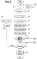
- FIG. 2 shows a program flow chart for the first solution according to the invention.
- the first pressure level p1 is then set, e.g. B. 100 bar.
- a second pressure level p2 (1) is set. The starting value of this second pressure level is z. B. 1 bar, ie atmospheric pressure.
- the volume flow Q (1) which is established is then measured.
- step S6 the second parameter K2 (1) is determined. This results from the measured volume flow Q (1) and the first p1 and second p2 pressure level. Based this first K1 (1) and second parameter K2 (1) then becomes the first operating point B (1) determined.
- step S8 it is checked whether the operating point B (i) in the permissible range. The first time the loop is run, this request is always positive, since the first operating point B (1) serves as the base point. It is then checked in step S9 whether the first parameter K1 (1) is equal to the limit value GW according to FIG. 1. Since this is the first Pass is not yet the case, the query result is negative.
- the program branches then to step S10, in which the count variable i is incremented.
- step S11 the second pressure level p2 (1) by a predeterminable value dp, z. B. 1 bar increased. Herewith is the loop closed.
- step S8 is the further one Operating point B (i) is not within the permissible range
- the program branches to the point B. This branch is described in connection with Figures 3 A to 3 C. Becomes determined in step S9 that the first parameter K1 (i) is equal to the limit value GW, so the injector is evaluated as error-free in step S12. It will be a positive test result detected.
- the program sequence is now finished.
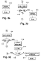
- FIGS. 3A to 3C Three alternative subroutines are shown in FIGS. 3A to 3C. These subroutines are activated when an operating point B (i) lies in the inadmissible range during the program run according to FIG. 2 in step S8.
- the injector is then immediately recognized as faulty in step S13 and a negative test result is detected.
- the program sequence is then ended.
- a sum memory SUM is increased by 1 in step S14.
- the number of operating points in the inadmissible range of the characteristic field is counted in this total memory.
- step S15 it is then checked whether the content of the sum memory SUM is less than a limit value GW.
- step S15 If the result of the query is positive, ie the number of inadmissible operating points B (i) has not yet exceeded the limit value GW, the program branches to point C in the program flow chart of FIG. 2. If the result of the query is negative in step S15, the injector becomes defective in step S16 determined and a negative test result detected. The program sequence is then ended.
- FIG. 3C shows a third alternative, which has the identical steps S14, S15 and S16 according to FIG. 3B contains.
- a result memory is stored in step S17 N incremented. This result memory N counts the faulty injectors. After that In step S18, it is checked whether the number of faulty injectors exceeds a limit GW is. If this is not the case, the program flow branches to point A of the Program flow chart of Figure 2. If the result of the query is positive, i. H. the number of faulty injectors is greater than the limit value GW, this becomes in step S19 Manufacturing process determined as defective. The program sequence is then ended.
- FIG. 4 shows a program flow chart of the second solution according to the invention.
- Steps S1 to S7 correspond to the same steps from FIG. 2, so that there is no further description at this point.
- step S8 it is checked whether the run variable i is 2. This is not the case during the first program run, so that the program continues at step S9 and the run variable i is increased by 1.
- step S10 the second pressure level p2 (i) is increased by a predeterminable value dp.
- the loop is hereby closed, ie the program continues with step S3.
- the second operating point B2 is determined during the second program run. Since the check at step S8 shows that the running variable i is equal to 2, the process continues with step S11.
- step S11 the deviation from the first B1 to the second B2 operating point is determined. This can be done by forming a difference or by forming a quotient.
- step S12 it is checked whether the deviation dB is greater than a limit value GW.
- the limit value dB in FIG. 1 can correspond, for example, to the difference between the two ordinate values K2 (1) and point A. A value of 1, 2 has proven itself in practice. If this is not the case, the injector is assessed as error-free in step S13 and a positive test result is detected. If the test in step S12 shows that the deviation dB is greater than the limit value GW, the injector is determined as faulty in step S14 and a negative test result is detected. The program flow chart is then ended.
Landscapes
- Engineering & Computer Science (AREA)
- Chemical & Material Sciences (AREA)
- Combustion & Propulsion (AREA)
- Mechanical Engineering (AREA)
- General Engineering & Computer Science (AREA)
- Combined Controls Of Internal Combustion Engines (AREA)
- Measuring Volume Flow (AREA)
Abstract
Es wird ein Verfahren zum Prüfen einer Drosselstelle, insbesondere der Drosselstelle eines Injektors vorgeschlagen. Diese wird von einer Pumpe mit einem ersten konstanten Druckniveau (p1) primärseitig beaufschlagt wobei der von der Pumpe gelieferte Volumenstrom Q des hydraulischen Druckmediums erfaßt wird. Es wird ein erster und weitere Betriebspunkte bestimmt. Die weiteren Betriebspunkte werden über die Veränderung eines zweiten, vorgebbaren sekundärseitigen Druckniveau (p2) ermittelt. Der erste Betriebspunkt bestimmt maßgeblich ein Kennlinienfeld (KF), welches ein Bereich zulässiger und nicht zulässiger Betriebspunkte aufweist. Anhand der Position der weiteren Betriebspunkte im Kennlinienfeld (KF) wird ein positives bzw. negatives Prüfergebnis detektiert.A method for testing a throttle point, in particular the throttle point of an injector, is proposed. This is acted upon by a pump with a first constant pressure level (p1) on the primary side, whereby the volume flow Q of the hydraulic pressure medium supplied by the pump is recorded. A first and further operating points are determined. The other operating points are determined by changing a second, predeterminable secondary pressure level (p2). The first operating point determines a characteristic field (KF), which has a range of permissible and non-permissible operating points. A positive or negative test result is detected on the basis of the position of the further operating points in the characteristic field (KF).
Description
Die Erfindung betrifft ein Verfahren zum Prüfen einer Drosselstelle, insbesondere der Drosselstelle eines Injektors auf einem Prüfstand. Der Injektor wird hierbei von einer Pumpe mit einem ersten konstanten Druckniveau primärseitig beaufschlagt. Zusätzlich wird der von der Pumpe bereitgestellte Volumenstrom des hydraulischen Druckmediums erfaßt.The invention relates to a method for testing a throttle point, in particular the Throttle point of an injector on a test bench. The injector is used by one Pump applied with a first constant pressure level on the primary side. In addition becomes the volume flow of the hydraulic pressure medium provided by the pump detected.
Bei Common-Rail-Systemen wird die Konstanz von Einspritzung zu Einspritzung maßgeblich über die Konstanz der Zerstäubung des Kraftstoffes bestimmt. Der Grad der Zerstäubung wiederum hängt eindeutig vom Injektor ab. Da bekanntermaßen die Güte der Injektoren innerhalb einer Serie streuen können, werden diese auf einem Prüfstand bewertet. Ein derartigen Prüfstand ist zum Beispiel aus der DE 31 28 072 C2 bekannt. Hierbei wird eine Einspritzdüse mit Düsenhalter auf Durchflußmenge, Öffnungsdruck, Schnarrverhalten, Dichtheit der Düsenhalterkombination, Sitzdichtheit und Nadelspiel der Düse geprüft. In der Praxis hat sich jedoch gezeigt, daß die statische Bestimmung der Güte eine Injektors auf einem derartigen Prüfstand eher unvollkommen das Verhalten desselben Injektors in dynamischem Betrieb, d. h. nach Einbau in eine Brennkraftmaschine, wiederspiegelt. Im Extremfall kann dies dazu führen, daß ein auf dem Prüfstand positiv bewerteter Injektor nach Einbau in die Brennkraftmaschine zu sehr unterschiedlichen Einspritzergebnissen führen kann.With common rail systems, the consistency from injection to injection is decisive determined on the constancy of the atomization of the fuel. The degree of atomization again clearly depends on the injector. As is well known, the quality of the injectors can spread within a series, they are evaluated on a test bench. On Such a test bench is known for example from DE 31 28 072 C2. Here is a Injection nozzle with nozzle holder on flow rate, opening pressure, click behavior, Tightness of the nozzle holder combination, seat tightness and needle clearance of the nozzle checked. In In practice, however, it has been shown that the static determination of the quality is an injector on such a test bench the behavior of the same injector is rather imperfect dynamic operation, d. H. after installation in an internal combustion engine, reflected. in the In extreme cases, this can lead to an injector being assessed positively on the test bench after installation in the internal combustion engine to very different injection results can lead.
Ausgehend vom zuvor beschriebenen Stand der Technik liegt der Erfindung insofern die Aufgabe zugrunde diesen weiterzuentwickeln.Starting from the prior art described above, the invention lies in that The task is to develop this further.
Eine erste erfindungsgemäße Lösung besteht darin, daß ein erster und weitere Betriebspunkte ermittelt werden, wobei der erste Betriebspunkt maßgeblich ein Kennlinienfeld bestimmt. Die weiteren Betriebspunkte werden dem Kennlinienfeld zugeordnet, welches einen Bereich zulässiger und nicht zulässiger Betriebspunkte aufweist. Anhand der Position der weiteren Betriebspunkte im Kennlinienfeld kann sodann ein positives bzw. negatives Prüfergebnis detektiert werden. A first solution according to the invention is that a first and another Operating points are determined, the first operating point being a significant one Characteristic field determined. The other operating points become the characteristic field assigned which is a range of permissible and non-permissible operating points having. Then, based on the position of the other operating points in the characteristic field a positive or negative test result can be detected.
In Ausgestaltung hierzu wird vorgeschlagen, daß sowohl der erste als auch die weiteren Betriebspunkte maßgeblich von einer ersten und zweiten Kenngröße bestimmt werden. Die erste Kenngröße berechnet sich hierbei aus dem ersten, primärseitigen Druckniveau und einem zweiten, vorgebbaren sekundärseitigen Druckniveau des Injektors. Die zweite Kenngröße wird maßgeblich vom gemessenen Volumenstrom und dem ersten und zweiten Druckniveau bestimmt. Gemäß Anspruch 3 werden die weiteren Betriebspunkte maßgeblich über die Erhöhung des zweiten Druckniveaus bestimmt.In an embodiment of this, it is proposed that both the first and the further Operating points are largely determined by a first and second parameter. The first parameter is calculated from the first pressure level on the primary side and a second, predeterminable secondary pressure level of the injector. The second The parameter is largely determined by the measured volume flow and the first and second Pressure level determined. According to claim 3, the other operating points largely determined by the increase in the second pressure level.
Beim erfindungsgemäßen Verfahren handelt es sich um ein dynamisches Meßverfahren. Ausgehend vom ersten Betriebspunkt werden die weiteren Betriebspunkte iterativ über die Erhöhung des sekundärseitigen Druckniveaus bestimmt. Da der Injektor unter dynamischen Gesichtspunkten geprüft wird, ist somit eine eindeutige Aussage über das dynamische Verhalten desselben Injektors im aktiven Betrieb, d. h. nach Einbau in der Brennkraftmaschine, möglich. Über die Bestimmung der ersten und zweiten Kenngröße läßt sich eine eindeutige Aussage über die Strömungsgeometrie innerhalb des geprüften Injektors treffen. Unter Strömungsgeometrie im Sinne der Erfindung ist der Grad der Verrundung einer Drosselstelle, deren Güte, zu verstehen. Mit dem erfindungsgemäßen Verfahren läßt sich ganz allgemein die Herstellungsqualität einer Drosselstelle verschiedenen Güteklassen zuordnen. Bei einem Injektor sind folgende maßgebliche Drosselstellen vorhanden: Steuerdrossel wie Zu- und Ablaufdrosseln als auch die Einspritzdüse selbst.The method according to the invention is a dynamic measuring method. Starting from the first operating point, the other operating points are iterated over the Increasing the secondary pressure level determined. Since the injector under dynamic aspects is checked, is therefore a clear statement about the dynamic behavior of the same injector in active operation, d. H. after installation in the Internal combustion engine, possible. By determining the first and second parameters can be a clear statement about the flow geometry within the tested Meet the injector. Under flow geometry in the sense of the invention is the degree of Rounding a throttle point, its quality to understand. With the invention In general, the process can be used to produce a throttle body assign different grades. The following are relevant for an injector Throttling points available: control throttle such as inlet and outlet throttles as well Injector itself.
Gemäß Anspruch 4 wird das Prüfverfahren solange durchgeführt, bis die erste Kenngröße
gleich einem Grenzwert ist. Der Grenzwert ist hierbei so gewählt, daß die Durchströmung
des Injektors im stabilen Bereich bleibt. Wie bei Anspruch 6 ausgeführt, wird ein negatives
Prüfergebnis dann detektiert, wenn ein Betriebspunkt dem nichtzulässigen Bereich des
Kennlinienfelds zugeordnet wird. Alternativ hierzu wird gemäß Anspruch 7 ein nicht
zulässiger Betriebspunkt in einem Summenspeicher gezählt. Erst wenn der Inhalt des
Summenspeichers einen Grenzwert übersteigt, wird ein negatives Prüfergebnis detektiert,
d. h. der Injektor ist fehlerbehaftet. Über diese Ausgestaltung wird der Vorteil erzielt, daß
die Toleranz der Meßkette ebenfalls mitberücksichtigt wird. According to
Eine zweite erfindungsgemäße Lösung der Aufgabe besteht darin, daß ein erster und zweiter Betriebspunkt ermittelt werden, eine Abweichung vom ersten und zweiten Betriebspunkt bestimmt wird und dann ein negatives Prüfergebnis detektiert wird, wenn die Abweichung einen Grenzwert übersteigt. Hierbei werden der erste und zweite Betriebspunkt wie zuvor beschrieben in Abhängigkeit der ersten und zweiten Kenngröße bestimmt. Dieses Zweipunkt-Prüfverfahren bietet den Vorteil, daß eine größere Anzahl von Injektoren innerhalb einer bestimmten Zeit bewertet werden können.A second solution to the problem of the invention is that a first and second operating point can be determined, a deviation from the first and second Operating point is determined and then a negative test result is detected if the deviation exceeds a limit. This will be the first and second Operating point as described above depending on the first and second parameters certainly. This two-point test method offers the advantage that a larger number of Injectors can be evaluated within a certain time.
In den Figuren ist ein bevorzugtes Ausführungsbeispiel der Erfindung dargestellt. Es zeigen:
- Figur 1:
- ein Diagramm
- Figur 2:
- Programmablaufplan der ersten Lösung
- Figur 3 A, B, C:
- Unterprogramm zu Figur 2
- Figur 4:
- Programmablaufplan der zweiten Lösung
- Figure 1:
- a diagram
- Figure 2:
- Program flowchart of the first solution
- Figure 3 A, B, C:
- Subroutine for Figure 2
- Figure 4:
- Program flow chart of the second solution
In Figur 1 ist ein Diagramm dargestellt. Auf der Abszisse ist dabei die erste Kenngröße K1
aufgetragen. Auf der Ordinate ist die zweite Kenngröße K2 aufgetragen. Die erste
Kenngröße K1 berechnet sich aus dem Druckverhältnis des ersten p1 und zweiten p2
Druckniveaus gemäß folgender Beziehung:
- p1
- primärseitiges am Injektor anstehendes Druckniveau (Injektor-Eingang)
- p2
- sekundärseitiges Druckniveau (Injektor-Ausgang)
- p1
- primary pressure level at the injector (injector inlet)
- p2
- secondary pressure level (injector outlet)
Die zweite Kenngröße K2 berechnet sich aus dem gemessenen Volumenstrom Q und dem ersten p1 und zweiten Druckniveau p2. Diese zweite Kenngröße K2 beschreibt ganz allgemein die tatsächlich durchströmte Fläche in einer Drosselstelle, welche der Injektor darstellt. Diese zweite Kenngröße K2 kann analytisch über die Bernoulli-Gleichung berechnet werden. Bekanntermaßen ist die durchströmte Fläche proportional dem Volumenstrom und umgekehrt proportional der Druckdifferenz zwischen ersten p1 und zweiten p2 Druckniveau.The second parameter K2 is calculated from the measured volume flow Q and the first p1 and second pressure level p2. This second parameter K2 describes completely generally the area actually flowed through in a throttle point, which the injector represents. This second parameter K2 can be analyzed analytically using the Bernoulli equation be calculated. As is known, the area flowed through is proportional to that Volume flow and inversely proportional to the pressure difference between the first p1 and second p2 pressure level.
In der Figur 1 sind mehrere Kennlinien dargestellt. Der Kurvenzug ACB(1) und K2(1) stellt hierbei den zulässigen Bereich dar. Der Ablauf des Prüfverfahrens ist folgendermaßen:Several characteristics are shown in FIG. The curve ACB (1) and K2 (1) represents the permitted range. The test procedure is as follows:
Zu Beginn wird ein erster Betriebspunkt B(1) bestimmt. Dieser erste Betriebspunkt wird
aus der ersten Kenngröße K1, und der zweiten Kenngröße K2 bestimmt. In Figur 1
entsprechend den beiden Punkten K1(1) und K2(1). Der erste Betriebspunkt B(1) bestimmt
hier maßgeblich das Kennlinienfeld. Mit anderen Worten: der erste Betriebspunkt B(1)
dient als Bezugspunkt für alle weiteren Betriebspunkte B(i). Dies ist in Figur 1 als
veränderbare Basislinie, entsprechend der Strecke K2(1) und B(1) dargestellt, Pfeile I und
II.
Typische Werte zur Bestimmung des ersten Betriebspunkts B(1) sind z. B. p1 = 100 bar
und p2 = 1 bar. Danach wird ein weiterer Betriebspunkt bestimmt indem das zweite
Druckniveau p2 um einen vorgebbaren Wert dp, z. B. 1 bar, erhöht wird. Dieser weitere
Betriebspunkt, in Figur 1 mit B(i) bezeichnet, wird sodann dem Kennlinienfeld zugeordnet.
Zu diesem Betriebspunkt B(i) gehört der Abszissenwert K1(i) und der Ordinatenwert K2(i).
In Figur 1 liegt dieser weitere Betriebspunkt B(i) im zulässigen Bereich des Kennlinienfelds.
Der nächste Betriebspunkt wird eingestellt, indem das zweite Druckniveau p2 wiederum
erhöht wird. Es wird somit eine iterative Schleife durchlaufen, wobei bei jedem Durchlauf
ein weiterer Betriebspunkt B(i) (i = 1, 2, 3 ...) bestimmt wird.At the beginning, a first operating point B (1) is determined. This first operating point is determined from the first parameter K1 and the second parameter K2. In Figure 1 corresponding to the two points K1 (1) and K2 (1). The first operating point B (1) largely determines the characteristic field here. In other words: the first operating point B (1) serves as a reference point for all further operating points B (i). This is shown in FIG. 1 as a changeable baseline, corresponding to the route K2 (1) and B (1), arrows I and II.
Typical values for determining the first operating point B (1) are e.g. B. p1 = 100 bar and p2 = 1 bar. Then another operating point is determined by the second pressure level p2 by a predeterminable value dp, z. B. 1 bar is increased. This further operating point, designated B (i) in FIG. 1, is then assigned to the characteristic field. The abscissa value K1 (i) and the ordinate value K2 (i) belong to this operating point B (i). In Figure 1, this further operating point B (i) lies in the permissible range of the characteristic field. The next operating point is set by increasing the second pressure level p2 again. An iterative loop is thus run through, with a further operating point B (i) (i = 1, 2, 3 ...) being determined with each run.
Liegen alle ermittelten Betriebspunkte B(i) innerhalb des zulässigen Bereichs, so ist das
Prüfverfahren dann beendet, wenn die erste Kenngröße K1 gleich einem Grenzwert GW ist.
In Figur 1 ist dieser Grenzwert GW auf der Abzisse dargestellt. Der Grenzwert GW ist
hierbei so gewählt, daß eine fehlerfreie Aussage über die Strömungsverhältnisse noch
getroffen werden kann. Mit anderen Worten: Werte von K1 zwischen den Ursprung und
diesem Grenzwert GW werden nicht ermittelt, weil dies einen instabilen Strömungszustand
beschreiben würde. Eine typischer Wert für diesen Grenzwert GW ist z. B. der
mathematische Wert 1, d. h. p1 = 100 bar und p2 = 50 bar. Wird festgestellt, daß ein
Betriebspunkt B(i) im nichtzulässigen Bereich des Kennlinienfelds liegt, so wird der
gemessene Injektor als fehlerbehaftet ermittelt, d. h. ein negatives Prüfergebnis wird
detektiert.
Als Alternative hierzu kann das Verfahren auch so ausgeführt sein, daß ein negatives
Prüfergebnis erst dann detektiert wird, wenn eine bestimmte Anzahl von Betriebspunkten
außerhalb des zulässigen Bereichs liegt. Als Extremwert kann z. B. dies so ausgeführt sein,
daß für eine fehlerbehafteten Injektor dessen komplette Kennlinie erfaßt wird. In Figur 1
ist z. B. eine derartige nicht im zulässigen Bereich liegende Kennlinie mit den Punkten
DEB (1) dargestellt.If all determined operating points B (i) lie within the permissible range, the test procedure is ended when the first parameter K1 is equal to a limit value GW. This limit value GW is shown on the abscissa in FIG. The limit value GW is selected so that an error-free statement about the flow conditions can still be made. In other words, values of K1 between the origin and this limit value GW are not determined because this would describe an unstable flow state. A typical value for this limit value GW is e.g. B. the
As an alternative to this, the method can also be carried out in such a way that a negative test result is only detected when a certain number of operating points lie outside the permissible range. As an extreme value, e.g. B. this can be carried out so that the complete characteristic curve is detected for a faulty injector. In Figure 1, for. B. such a characteristic curve not in the permissible range is shown with the points DEB (1).
Zusätzlich kann das erfindungsgemäße Verfahren so ausgeführt sein, daß die Anzahl der Injektoren mit einem negativen Prüfergebnis gezählt werden. Hierdurch läßt sich ermitteln, ob das Herstellungsverfahren der Injektoren insgesamt fehlerbehaftet ist. Es läßt sich somit eine sogenannte "100%-Prüfung" durchführen.In addition, the inventive method can be carried out so that the number of Injectors with a negative test result can be counted. In this way it can be determined whether the manufacturing process of the injectors is defective overall. It can be thus carry out a so-called "100% test".
In Figur 2 ist ein Programmablaufplan für die erste erfindungsgemäße Lösung dargestellt.
Im Schritt S1 wird eine Zählvariable i = 1 gesetzt. Im Schritt S2 wird sodann das erste
Druckniveau p1 eingestellt, z. B. 100 bar. Bei der Schritt S3 wird ein zweites Druckniveau
p2(1) eingestellt. Der Startwert dieses zweiten Druckniveaus liegt bei z. B. 1 bar, d. h.
Atmosphärendruck. Bei Schritt S4 wird sodann der sich einstellende Volumenstrom Q(1)
gemessen. Bei Schritt S5 wird aus dem ersten p1 und zweiten p2(1) Druckniveau die erste
Kenngröße K1(1) bestimmt. Dies kann gemäß der folgenden Bezeichnung erfolgen:
Bei Schritt S6 wird die zweite Kenngröße K2(1) bestimmt. Diese ergibt sich aus dem gemessenen Volumenstrom Q(1) und dem ersten p1 und zweiten p2 Druckniveau. Anhand dieser ersten K1(1) und zweiten Kenngröße K2(1) wird sodann der erste Betriebspunkt B(1) bestimmt. Bei der Abfrage im Schritt S8 wird geprüft, ob der Betriebspunkt B(i) im zulässigen Bereich liegt. Beim ersten Durchlauf der Schleife ist diese Anfrage stets positiv, da der erste Betriebspunkt B(1) als Basispunkt dient. Im Schritt S9 wird sodann geprüft ob die erste Kenngröße K1(1) gleich dem Grenzwert GW gemäß Fig. 1 ist. Da dies beim ersten Durchlauf noch nicht der Fall ist, ist das Abfrageergebnis negativ. Das Programm verzweigt sodann zum Schritt S10, bei dem die Zählvariable i inkrementiert wird. Bei Schritt S11 wird das zweite Drucknivau p2(1) um einen vorgebbaren Wert dp, z. B. 1 bar, erhöht. Hiermit ist die Schleife geschlossen.In step S6, the second parameter K2 (1) is determined. This results from the measured volume flow Q (1) and the first p1 and second p2 pressure level. Based this first K1 (1) and second parameter K2 (1) then becomes the first operating point B (1) determined. When querying in step S8, it is checked whether the operating point B (i) in the permissible range. The first time the loop is run, this request is always positive, since the first operating point B (1) serves as the base point. It is then checked in step S9 whether the first parameter K1 (1) is equal to the limit value GW according to FIG. 1. Since this is the first Pass is not yet the case, the query result is negative. The program branches then to step S10, in which the count variable i is incremented. At step S11 the second pressure level p2 (1) by a predeterminable value dp, z. B. 1 bar increased. Herewith is the loop closed.
Beim nächsten Programmdurchlauf wird in den Schritten S3 bis S7 ein weiterer Betriebspunkt B(i) bestimmt. Ergibt die Abfrage im Schritt S8 das der weitere Betriebspunkt B(i) nicht im zulässigen Bereich liegt, so verzweigt das Programm zum Punkt B. Diese Verzweigung wird in Verbindung mit den Figuren 3 A bis 3 C beschrieben. Wird bei Schritt S9 festgestellt, daß die erste Kenngröße K1(i) gleich dem Grenzwert GW ist, so wird bei Schritt S12 der Injektor als fehlerfrei bewertet. Es wird ein positives Prüfergebnis detektiert. Damit ist der Programmablauf beendet.The next time the program is run, a further step is carried out in steps S3 to S7 Operating point B (i) determined. If the query in step S8 is the further one Operating point B (i) is not within the permissible range, the program branches to the point B. This branch is described in connection with Figures 3 A to 3 C. Becomes determined in step S9 that the first parameter K1 (i) is equal to the limit value GW, so the injector is evaluated as error-free in step S12. It will be a positive test result detected. The program sequence is now finished.
In den Figuren 3 A bis 3 C sind drei alternative Unterprogramme dargestellt. Diese
Unterprogramme werden dann aktiviert, wenn beim Programm-Durchlauf gemäß Figur 2
im Schritt S8 ein Betriebspunkt B(i) im nichtzulässigen Bereich liegt. Bei Figur 3 A wird
sodann im Schritt S13 der Injektor unmittelbar als fehlerhaft erkannt und ein negatives
Prüfungsergebnis detektiert. Danach ist der Programmablauf beendet.
In Figur 3 B wird im Schritt S14 ein Summenspeicher SUM um 1 erhöht. In diesem
Summenspeicher wird die Anzahl der Betriebspunkte, die im nichtzulässigen Bereich des
Kennlinienfelds liegen, gezählt. Bei Schritt S15 wird sodann geprüft, ob der Inhalt des
Summenspeichers SUM kleiner einem Grenzwert GW ist. Bei positivem Abfrageergebnis,
d. h. die Anzahl der nichtzulässigen Betriebspunkte B(i) hat den Grenzwert GW noch nicht
überschritten, verzweigt das Programm zum Punkt C im Programmablaufplan der Figur 2.
Bei negativem Abfrageergebnis im Schritt S15 wird als Folge bei Schritt S16 der Injektor
als fehlerhaft bestimmt und ein negatives Prüfergebnis detektiert. Danach ist der
Programmablauf beendet. Three alternative subroutines are shown in FIGS. 3A to 3C. These subroutines are activated when an operating point B (i) lies in the inadmissible range during the program run according to FIG. 2 in step S8. In FIG. 3A, the injector is then immediately recognized as faulty in step S13 and a negative test result is detected. The program sequence is then ended.
In FIG. 3B, a sum memory SUM is increased by 1 in step S14. The number of operating points in the inadmissible range of the characteristic field is counted in this total memory. In step S15 it is then checked whether the content of the sum memory SUM is less than a limit value GW. If the result of the query is positive, ie the number of inadmissible operating points B (i) has not yet exceeded the limit value GW, the program branches to point C in the program flow chart of FIG. 2. If the result of the query is negative in step S15, the injector becomes defective in step S16 determined and a negative test result detected. The program sequence is then ended.
In Figur 3 C ist eine dritte Alternative dargestellt, welche die identischen Schritte S14, S15 und S16 gemäß der Figur 3 B enthält. Zusätzlich wird bei Schritt S17 ein Ergebnisspeicher N inkrementiert. Dieser Ergebnisspeicher N zählt die fehlerhaften Injektoren. Danach wird bei Schritt S18 geprüft, ob die Anzahl der fehlerhaften Injektoren größer einem Grenzwert GW ist. Ist dies nicht der Fall, so verzweigt der Programmablauf zum Punkt A des Programmablaufplans der Figur 2. Bei positivem Abfrageergebnis, d. h. die Anzahl der fehlerhaften Injektoren ist größer als der Grenzwert GW, wird bei Schritt S19 das Herstellungsverfahren als fehlerhaft bestimmt. Danach ist der Programmablauf beendet.FIG. 3C shows a third alternative, which has the identical steps S14, S15 and S16 according to FIG. 3B contains. In addition, a result memory is stored in step S17 N incremented. This result memory N counts the faulty injectors. After that In step S18, it is checked whether the number of faulty injectors exceeds a limit GW is. If this is not the case, the program flow branches to point A of the Program flow chart of Figure 2. If the result of the query is positive, i. H. the number of faulty injectors is greater than the limit value GW, this becomes in step S19 Manufacturing process determined as defective. The program sequence is then ended.
In Figur 4 ist ein Programmablaufplan der zweiten erfindungsgemäßen Lösung dargestellt.
Die Schritte S1 bis S7 entsprechen denselben Schritten aus Figur 2, so daß auf eine
erneute Schilderung an dieser Stelle verzichtet wird. Bei Schritt S8 wird geprüft, ob die
Laufvariable i gleich 2 ist. Beim ersten Programmdurchlauf ist dies nicht der Fall, so daß
das Programm bei Schritt S9 fortfährt und die Laufvariable i um 1 erhöht wird. Bei Schritt
S10 wird das zweite Druckniveau p2(i) um einen vorgebbaren Wert dp erhöht. Hiermit ist
die Schleife geschlossen, d. h. das Programm fährt beim Schritt S3 fort.
Beim zweiten Programmdurchlauf wird der zweite Betriebspunkt B2 bestimmt. Da die
Prüfung bei Schritt S8 ergibt, daß die Laufvariable i gleich 2 ist, wird mit Schritt S11
fortgefahren. Bei Schritt S11 wird die Abweichung vom ersten B1 zum zweiten B2
Betriebspunkt bestimmt. Dies kann durch Differenzbildung oder durch Quotientenbildung
erfolgen. Bei Schritt S12 wird geprüft ob die Abweichung dB größer einem Grenzwert GW
ist. Der Grenzwert dB kann in der Fig. 1 zum Beispiel der Differenz der beiden
Ordinatenwerte K2(1) und Punkt A entsprechen. In der Praxis hat sich ein Wert von 1, 2
bewährt. Ist dies nicht der Fall, so wird bei Schritt S13 der Injektor als fehlerfrei bewertet
und ein positives Prüfungsergebnis detektiert. Ergibt die Prüfung bei Schritt S12 daß die
Abweichung dB größer dem Grenzwert GW ist, so wird im Schritt S14 der Injektor als
fehlerhaft bestimmt und ein negatives Prüfungsergebnis detektiert. Danach ist der
Programmablaufplan beendet. FIG. 4 shows a program flow chart of the second solution according to the invention. Steps S1 to S7 correspond to the same steps from FIG. 2, so that there is no further description at this point. In step S8, it is checked whether the run variable i is 2. This is not the case during the first program run, so that the program continues at step S9 and the run variable i is increased by 1. In step S10, the second pressure level p2 (i) is increased by a predeterminable value dp. The loop is hereby closed, ie the program continues with step S3.
The second operating point B2 is determined during the second program run. Since the check at step S8 shows that the running variable i is equal to 2, the process continues with step S11. In step S11, the deviation from the first B1 to the second B2 operating point is determined. This can be done by forming a difference or by forming a quotient. In step S12, it is checked whether the deviation dB is greater than a limit value GW. The limit value dB in FIG. 1 can correspond, for example, to the difference between the two ordinate values K2 (1) and point A. A value of 1, 2 has proven itself in practice. If this is not the case, the injector is assessed as error-free in step S13 and a positive test result is detected. If the test in step S12 shows that the deviation dB is greater than the limit value GW, the injector is determined as faulty in step S14 and a negative test result is detected. The program flow chart is then ended.
- S1 bis S19S1 to S19
- Schrittesteps
- KFKF
- KennlinienfeldCharacteristic field
Claims (13)
dadurch gekennzeichnet,
das ein erster (B(i), i=1) und weitere (B(i), i=2, 3, 4...) Betriebspunkte ermittelt werden, der erste Betriebspunkt (B(i), i=1) maßgeblich eine Kennlinienfeld (KF) bestimmt (KF=f(B(i)), die weiteren Betriebspunkte (B(i), i=2, 3, 4, ...) dem Kennlinienfeld (KF) zugeordnet werden, wobei das Kennlinienfeld (KF) einen Bereich zulässiger und nicht zulässiger Betriebspunkte aufweist und anhand der Position der weiteren Betriebspunkte (B(i), i=2, 3, 4...) im Kennlinienfeldes (KF) ein positives bzw. negatives Prüfergebnis detektiert wird.Method for testing a throttle point, in particular the throttle point of an injector, to which a first, constant pressure level (p1) is applied by a pump and which detects the volume flow (Q) of the hydraulic pressure medium provided by the pump,
characterized by
that a first (B (i), i = 1) and further (B (i), i = 2, 3, 4 ...) operating points are determined, the first operating point (B (i), i = 1) is decisive a characteristic field (KF) determines (KF = f (B (i)), the other operating points (B (i), i = 2, 3, 4, ...) are assigned to the characteristic field (KF), the characteristic field ( KF) has a range of permissible and non-permissible operating points and a positive or negative test result is detected based on the position of the further operating points (B (i), i = 2, 3, 4 ...) in the characteristic field (KF).
Applications Claiming Priority (2)
| Application Number | Priority Date | Filing Date | Title |
|---|---|---|---|
| DE1998150221 DE19850221C1 (en) | 1998-10-31 | 1998-10-31 | Method for testing a throttle point, in particular a throttle point of an injector |
| DE19850221 | 1998-10-31 |
Publications (2)
| Publication Number | Publication Date |
|---|---|
| EP0997635A2 true EP0997635A2 (en) | 2000-05-03 |
| EP0997635A3 EP0997635A3 (en) | 2002-04-10 |
Family
ID=7886251
Family Applications (1)
| Application Number | Title | Priority Date | Filing Date |
|---|---|---|---|
| EP99121321A Withdrawn EP0997635A3 (en) | 1998-10-31 | 1999-10-26 | Method for testing a throttle point, especially a throttle point of an injector |
Country Status (2)
| Country | Link |
|---|---|
| EP (1) | EP0997635A3 (en) |
| DE (1) | DE19850221C1 (en) |
Families Citing this family (4)
| Publication number | Priority date | Publication date | Assignee | Title |
|---|---|---|---|---|
| DE10115924A1 (en) * | 2001-03-30 | 2002-10-24 | Bosch Gmbh Robert | Test bench for determining pressures on pressurized components |
| DE10133357C1 (en) * | 2001-07-13 | 2003-03-13 | Mtu Friedrichshafen Gmbh | Control and regulation method for IC engine adjusts air component of fuel/air mixture supplied to engine |
| DE102004006896A1 (en) | 2004-02-12 | 2005-09-15 | Mtu Friedrichshafen Gmbh | Method for control and regulation of an IC engine with common-rail system uses calculation of injection end and injection begin deviations to evaluate fuel injectors |
| DE102006034514B4 (en) * | 2006-07-26 | 2014-01-16 | Mtu Friedrichshafen Gmbh | Method for controlling an internal combustion engine |
Family Cites Families (6)
| Publication number | Priority date | Publication date | Assignee | Title |
|---|---|---|---|---|
| US2293725A (en) * | 1941-03-29 | 1942-08-25 | Ernest F Flock | Orifice comparator |
| DE2630521C3 (en) * | 1976-07-07 | 1981-12-10 | Volkswagenwerk Ag, 3180 Wolfsburg | Flow bank |
| DE3128072A1 (en) * | 1980-11-08 | 1982-06-24 | Robert Bosch Gmbh, 7000 Stuttgart | TEST STAND FOR TESTING INJECTION NOZZLES |
| DE3217111C2 (en) * | 1982-05-07 | 1985-01-03 | Pierburg Gmbh & Co Kg, 4040 Neuss | Method for testing and / or setting throttle points with variable cross-section and device for carrying out this method |
| US5373449A (en) * | 1988-08-13 | 1994-12-13 | Amchem Company Limited | Method of producing a multi-apertured workpiece |
| DE19632339A1 (en) * | 1996-08-10 | 1998-02-12 | Bosch Gmbh Robert | Method and device for monitoring a flow limiter of a fuel metering system of an internal combustion engine |
-
1998
- 1998-10-31 DE DE1998150221 patent/DE19850221C1/en not_active Expired - Fee Related
-
1999
- 1999-10-26 EP EP99121321A patent/EP0997635A3/en not_active Withdrawn
Also Published As
| Publication number | Publication date |
|---|---|
| DE19850221C1 (en) | 2000-05-04 |
| EP0997635A3 (en) | 2002-04-10 |
Similar Documents
| Publication | Publication Date | Title |
|---|---|---|
| DE19951517B4 (en) | Metal diaphragm pulsation absorber for high pressure fuel pump | |
| WO2002001066A1 (en) | Fuel injection valve for internal combustion engines | |
| EP1129287A1 (en) | Injection nozzle for an internal combustion engine with annular groove in said nozzle needle | |
| EP0920611B1 (en) | Diagnostic module for testing the tightness of a container | |
| DE2943896A1 (en) | FUEL INJECTION NOZZLE FOR INTERNAL COMBUSTION ENGINES | |
| EP0370091A1 (en) | Automatic control process and device, in particular lambda control. | |
| DE19850221C1 (en) | Method for testing a throttle point, in particular a throttle point of an injector | |
| DE3309235A1 (en) | CONTROL METHOD FOR AN INTERNAL COMBUSTION ENGINE | |
| DE19501683A1 (en) | Pilot operated proportional pressure relief valve | |
| DE10252567B4 (en) | Combustion state detection device for an internal combustion engine | |
| DE2946747A1 (en) | MOTOR BRAKE FOR MOTOR VEHICLES | |
| DE4131564C2 (en) | Potentiometer | |
| DE19963901A1 (en) | Method for operating a catalyst of an internal combustion engine | |
| DE10022275A1 (en) | Overpressure valve for fuel supply system has valve seat guide part that accepts valve ball and is of width up to 60 microns larger than ball diameter so ball can slide within guide part | |
| DE2514689A1 (en) | Silencer for pulsating gas flow noise - cheap, light, compact; for IC engines, and pressure reducing valves, has spring loaded plate stack | |
| DE69716227T2 (en) | PRESSURE LIMITING DEVICE IN A LUBRICATING OIL CIRCUIT OF AN INTERNAL COMBUSTION ENGINE | |
| WO1997015752A2 (en) | Method of monitoring a secondary air pump | |
| DE3303492A1 (en) | CONTROL VALVE | |
| DE3826526A1 (en) | METHOD AND DEVICE FOR ADJUSTING THE OPERATING SIZE OF AN INTERNAL COMBUSTION ENGINE | |
| DE102004012491B4 (en) | Method for determining defective actuators of an internal combustion engine | |
| DE19540529B4 (en) | Control valve of the lubricating oil circuit of an internal combustion engine | |
| WO2004076850A1 (en) | Blind hole and seat hole injection nozzle for an internal combustion engine, comprising a transition cone between the blind hole and the nozzle needle seat | |
| EP0909899A2 (en) | Method for mounting a sliding-contact bearing | |
| DE19931761A1 (en) | Blind hole injection nozzle for internal combustion engines with a rounded transition between blind hole and nozzle needle seat | |
| DE69206235T2 (en) | Fuel filter. |
Legal Events
| Date | Code | Title | Description |
|---|---|---|---|
| PUAI | Public reference made under article 153(3) epc to a published international application that has entered the european phase |
Free format text: ORIGINAL CODE: 0009012 |
|
| 17P | Request for examination filed |
Effective date: 19991026 |
|
| AK | Designated contracting states |
Kind code of ref document: A2 Designated state(s): AT BE CH CY DE DK ES FI FR GB GR IE IT LI LU MC NL PT SE Kind code of ref document: A2 Designated state(s): AT DE FR GB |
|
| AX | Request for extension of the european patent |
Free format text: AL;LT;LV;MK;RO;SI |
|
| RAP1 | Party data changed (applicant data changed or rights of an application transferred) |
Owner name: MTU FRIEDRICHSHAFEN GMBH |
|
| PUAL | Search report despatched |
Free format text: ORIGINAL CODE: 0009013 |
|
| AK | Designated contracting states |
Kind code of ref document: A3 Designated state(s): AT BE CH CY DE DK ES FI FR GB GR IE IT LI LU MC NL PT SE |
|
| AX | Request for extension of the european patent |
Free format text: AL;LT;LV;MK;RO;SI |
|
| AKX | Designation fees paid |
Free format text: AT BE CH CY LI |
|
| RBV | Designated contracting states (corrected) |
Designated state(s): AT DE FR GB |
|
| REG | Reference to a national code |
Ref country code: DE Ref legal event code: 8566 |
|
| 17Q | First examination report despatched |
Effective date: 20060726 |
|
| 17Q | First examination report despatched |
Effective date: 20060726 |
|
| STAA | Information on the status of an ep patent application or granted ep patent |
Free format text: STATUS: THE APPLICATION IS DEEMED TO BE WITHDRAWN |
|
| 18D | Application deemed to be withdrawn |
Effective date: 20070424 |