EP0997652A1 - Lager - Google Patents
Lager Download PDFInfo
- Publication number
- EP0997652A1 EP0997652A1 EP99307968A EP99307968A EP0997652A1 EP 0997652 A1 EP0997652 A1 EP 0997652A1 EP 99307968 A EP99307968 A EP 99307968A EP 99307968 A EP99307968 A EP 99307968A EP 0997652 A1 EP0997652 A1 EP 0997652A1
- Authority
- EP
- European Patent Office
- Prior art keywords
- bearing
- shell
- housing
- shells
- wall thickness
- Prior art date
- Legal status (The legal status is an assumption and is not a legal conclusion. Google has not performed a legal analysis and makes no representation as to the accuracy of the status listed.)
- Withdrawn
Links
- 238000002485 combustion reaction Methods 0.000 claims abstract description 6
- 238000004519 manufacturing process Methods 0.000 description 3
- 229910000831 Steel Inorganic materials 0.000 description 2
- 239000000463 material Substances 0.000 description 2
- 239000010959 steel Substances 0.000 description 2
- 239000000956 alloy Substances 0.000 description 1
- 229910045601 alloy Inorganic materials 0.000 description 1
- 239000001996 bearing alloy Substances 0.000 description 1
- 230000015556 catabolic process Effects 0.000 description 1
- 239000000470 constituent Substances 0.000 description 1
- 238000005336 cracking Methods 0.000 description 1
- 238000003754 machining Methods 0.000 description 1
- 238000000034 method Methods 0.000 description 1
- 238000010008 shearing Methods 0.000 description 1
- 238000004513 sizing Methods 0.000 description 1
Images
Classifications
-
- F—MECHANICAL ENGINEERING; LIGHTING; HEATING; WEAPONS; BLASTING
- F16—ENGINEERING ELEMENTS AND UNITS; GENERAL MEASURES FOR PRODUCING AND MAINTAINING EFFECTIVE FUNCTIONING OF MACHINES OR INSTALLATIONS; THERMAL INSULATION IN GENERAL
- F16C—SHAFTS; FLEXIBLE SHAFTS; ELEMENTS OR CRANKSHAFT MECHANISMS; ROTARY BODIES OTHER THAN GEARING ELEMENTS; BEARINGS
- F16C9/00—Bearings for crankshafts or connecting-rods; Attachment of connecting-rods
- F16C9/04—Connecting-rod bearings; Attachments thereof
Definitions
- the present invention relates to half-shell bearings for internal combustion engines.
- Half-shell sliding bearings generally employ a so-called "nick” or “notch” to provide axial location of the bearing shells in their housings, usually either the connecting rod (conrod) housings and/or the main bearing housings, in the engine.
- the nick is a small portion of the bearing wall adjacent the joint face and either at one end face or intermediate the bearing end faces which is sheared and moved in a radially outwardly direction relative to the bearing circumference and which locates in a machined recess in the bearing housing.
- the purpose of the nick is to provide accurate axial location of the bearing in its housing and, in some cases, to provide a fool-proof assembly method, for example to prevent a cap half-shell being fitted to the block and vice versa where the two half shells differ.
- the nick is not intended to prevent rotation of the bearing within the housing, rotation being prevented in most cases by the degree of interference between the bearing back and the housing.
- nick presents problems in the case of racing engines.
- Racing engines operating at high rotational speeds suffer from distortion of the housings due to the high loads generated and in this instance the nick not only provides axial location but also does provide some measure of resistance to circumferential movement of the bearing shells relative to their housing.
- Racing engine designers are not therefore, prepared to use nickless bearings in racing engines. In some racing applications bearings employing two nicks are used.
- the recess in the bearing bore due to the nick can cause breakdown of the hydrodynamic oil film which, in any case, is usually considerably thinner than on normal production engines.
- the recess required in the bearing housing to accommodate the nick can act as a stress raiser and cracking in this region between the recess and the bolt hole is not unknown. Again, this particular problem is exacerbated in racing engines due to the greater stresses involved.
- a combination of a bearing and a housing for said bearing in an internal combustion engine including two substantially semi-circular half-bearing shells comprising a first half-shell bearing having a first wall thickness and a second half-shell bearing having a second wall thickness wherein said first wall thickness is different from said second wall thickness and said first and second half shells have a substantially common bore diameter when assembled in said housing.
- the "wall thickness" of a bearing is its total thickness including any constituent layers such as steel backing layer and alloy bearing layer for example.
- the bearing may comprise more than two layers.
- the housing of the bearing and housing combination of the present invention may comprise a portion machined into a cylinder block or crankcase part of the engine or alternatively in a conrod (hereinafter referred to as "block") to accept one of the first or second half-shells and a corresponding "cap” part to accept the other half-shell. Since the wall thicknesses of the first and second half-shells are different from each other and the bore diameter is substantially the same it follows that the outer diameters of the first and second half-shells are different and that the block and cap housing parts have corresponding bore diameters to receive the shells.
- part of the joint face of the thicker half-shell butts up against the joint face of the housing of the other half-shell thus preventing rotation of the bearing pair.
- the bearing half-shells of the present invention do not require nicks and consequently the bearings do not suffer from the disadvantages set out above.
- Half bearings in their free state when not clamped together in a housing are slightly longer in circumferential length than their corresponding housing part. This is known as "crush" and is to allow the joint faces of two bearing halves to contact each other and exert a force to push them securely into their respective housings and create an interference fit therebetween.
- the joint face over the additional diameter compared with the other half shell may be relieved to enable good contact between the bearing half-shell joint faces to permit satisfactory clamping.
- a bearing comprising a pair of half-bearing shells including a first half-bearing shell and a second half-bearing shell each having a common bore diameter when in use but having different wall thicknesses from each other.
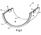
- the bearing 10 comprises a strong backing 12 from a material such as steel for example and a bearing alloy lining 14 bonded to the backing 12.
- the bearing back is indicated at 16 and the bore at 18.
- the joint faces are indicated at 20 and the bearing end faces at 22.
- a nick 24 is indicated on both joint faces 20 but may only be present on one joint face.
- the nick is generally pressed from the wall material by shearing in a press tool so as to form a tongue which extends radially outwardly beyond the diameter of the bearing back 16 to locate in a recess (not shown) in a co-operating housing (not shown).
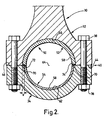
- FIG. 2 shows a bearing and bearing housing according to the present invention.
- the housing comprises a connecting rod 30 having a rod-half 32 and a cap-half 34, the two parts being secured together by nuts 36 and bolts 38 along a common joint line 40 made up of the joint face 44 of the rod-half 32 and the joint face 46 of the cap-half 34.
- a bearing 50 comprising a first half-bearing shell 52 and a second half-bearing shell 54, the two shells 52, 54 having a common bore 58 when assembled together in the housing 30.
- the first half shell 52 has wall thickness which is thicker than that of the second half shell 54. Consequently, the bore 60 in the rod-half 32 is greater than the bore 62 in the cap-half 34.
- both bores 60, 62 are coincident at 64.
- the portion of the wall thickness indicated at "x" of the first half shell 52 is slightly relieved at the joint faces 70 so as to enable the half shall joint faces 72, 74 to contact each other to permit satisfactory clamping therebetween and to allow a machining tolerance in the housing halves.
- the connecting rod 30 of Figure 2 could be substituted by a housing in an engine cylinder block or crankcase for example.
- the relative positions of the two bearing halves 52, 54 may be interchanged such that the thicker half 52 is housed in the cap-half 34 together with corresponding sizing thereof.
Landscapes
- Engineering & Computer Science (AREA)
- General Engineering & Computer Science (AREA)
- Mechanical Engineering (AREA)
- Shafts, Cranks, Connecting Bars, And Related Bearings (AREA)
- Mounting Of Bearings Or Others (AREA)
- Sliding-Contact Bearings (AREA)
Applications Claiming Priority (2)
| Application Number | Priority Date | Filing Date | Title |
|---|---|---|---|
| GBGB9823674.8A GB9823674D0 (en) | 1998-10-30 | 1998-10-30 | Bearings |
| GB9823674 | 1998-10-30 |
Publications (1)
| Publication Number | Publication Date |
|---|---|
| EP0997652A1 true EP0997652A1 (de) | 2000-05-03 |
Family
ID=10841493
Family Applications (1)
| Application Number | Title | Priority Date | Filing Date |
|---|---|---|---|
| EP99307968A Withdrawn EP0997652A1 (de) | 1998-10-30 | 1999-10-08 | Lager |
Country Status (5)
| Country | Link |
|---|---|
| US (1) | US6257768B1 (de) |
| EP (1) | EP0997652A1 (de) |
| JP (1) | JP2000199515A (de) |
| BR (1) | BR9904704A (de) |
| GB (1) | GB9823674D0 (de) |
Families Citing this family (8)
| Publication number | Priority date | Publication date | Assignee | Title |
|---|---|---|---|---|
| GB2423806B (en) | 2002-07-26 | 2007-04-18 | Cummins Inc | Connecting Rod Apparatus & Method |
| DE10322248B4 (de) * | 2003-05-13 | 2006-10-19 | Federal-Mogul Wiesbaden Gmbh & Co. Kg | System mit Welle und mindestens zwei Lagern und Vorrichtung zur Herstellung eines Systems mit Welle und mindestens zwei Lagern |
| US7354199B2 (en) * | 2005-06-01 | 2008-04-08 | Federal Mogul Worldwide, Inc. | Thrust bearing |
| CN101298849B (zh) * | 2007-04-30 | 2010-12-08 | 程大友 | 提高发动机效率的方法和装置 |
| JP5290738B2 (ja) | 2008-12-26 | 2013-09-18 | 大同メタル工業株式会社 | 内燃機関のクランク軸用分割型すべり軸受および分割型すべり軸受装置 |
| JP4994356B2 (ja) * | 2008-12-26 | 2012-08-08 | 大同メタル工業株式会社 | 内燃機関のクランク軸用分割型すべり軸受および分割型すべり軸受装置 |
| JP5089572B2 (ja) * | 2008-12-26 | 2012-12-05 | 大同メタル工業株式会社 | 内燃機関のクランク軸用分割型すべり軸受および分割型すべり軸受装置 |
| GB2619032B (en) * | 2022-05-24 | 2025-03-26 | Mahle Int Gmbh | Bearing and method of manufacture |
Citations (5)
| Publication number | Priority date | Publication date | Assignee | Title |
|---|---|---|---|---|
| US2821444A (en) * | 1955-02-23 | 1958-01-28 | Caterpillar Tractor Co | Bearing retaining means |
| DE2723585A1 (de) * | 1976-05-26 | 1977-12-08 | Gould Inc | Hydrodynamisches radialgleitlager |
| DE3619404A1 (de) * | 1986-06-09 | 1987-12-10 | Glyco Metall Werke | Aus lagerhaelften aufgebautes gleitlager als fuehrungslager |
| DE19510928A1 (de) * | 1994-03-25 | 1995-10-05 | Glyco Metall Werke | Lagerschale und ein in einem mit Lagerdeckel versehenen Lagerkörper eingebautes Radial-Gleitlager |
| FR2754023A1 (fr) * | 1996-09-30 | 1998-04-03 | Peugeot | Dispositif formant palier en deux parties pour un arbre |
Family Cites Families (4)
| Publication number | Priority date | Publication date | Assignee | Title |
|---|---|---|---|---|
| US4025131A (en) * | 1976-01-08 | 1977-05-24 | Henningsen Foods, Inc. | Removable sanitary hanger bearing |
| GB8720915D0 (en) | 1987-09-05 | 1987-10-14 | Coussinets Ste Indle | Bearings |
| AU621436B2 (en) * | 1988-12-26 | 1992-03-12 | Aichi Kikai Kogyo Kabushiki Kaisha | An outboard engine |
| JPH10299780A (ja) | 1997-04-29 | 1998-11-10 | Daido Metal Co Ltd | すべり軸受 |
-
1998
- 1998-10-30 GB GBGB9823674.8A patent/GB9823674D0/en not_active Ceased
-
1999
- 1999-10-08 EP EP99307968A patent/EP0997652A1/de not_active Withdrawn
- 1999-10-27 BR BR9904704-7A patent/BR9904704A/pt not_active Application Discontinuation
- 1999-10-29 US US09/430,399 patent/US6257768B1/en not_active Expired - Lifetime
- 1999-10-29 JP JP11307860A patent/JP2000199515A/ja active Pending
Patent Citations (5)
| Publication number | Priority date | Publication date | Assignee | Title |
|---|---|---|---|---|
| US2821444A (en) * | 1955-02-23 | 1958-01-28 | Caterpillar Tractor Co | Bearing retaining means |
| DE2723585A1 (de) * | 1976-05-26 | 1977-12-08 | Gould Inc | Hydrodynamisches radialgleitlager |
| DE3619404A1 (de) * | 1986-06-09 | 1987-12-10 | Glyco Metall Werke | Aus lagerhaelften aufgebautes gleitlager als fuehrungslager |
| DE19510928A1 (de) * | 1994-03-25 | 1995-10-05 | Glyco Metall Werke | Lagerschale und ein in einem mit Lagerdeckel versehenen Lagerkörper eingebautes Radial-Gleitlager |
| FR2754023A1 (fr) * | 1996-09-30 | 1998-04-03 | Peugeot | Dispositif formant palier en deux parties pour un arbre |
Also Published As
| Publication number | Publication date |
|---|---|
| BR9904704A (pt) | 2000-08-15 |
| JP2000199515A (ja) | 2000-07-18 |
| GB9823674D0 (en) | 1998-12-23 |
| US6257768B1 (en) | 2001-07-10 |
Similar Documents
| Publication | Publication Date | Title |
|---|---|---|
| US8251590B2 (en) | Anti-rotation bearing assembly and bearing | |
| US6634791B2 (en) | Shaft bearing member | |
| JP3388501B2 (ja) | すべり軸受 | |
| US6585419B2 (en) | Shaft bearing member | |
| EP1886033B1 (de) | Schublager | |
| EP0421619B1 (de) | Keramisches Lager | |
| JP2000179535A (ja) | 分割型コンロッドにおける軸受メタルの位置決め構造 | |
| EP0893326A2 (de) | Befestigung für eine Lenksäule | |
| EP1148260A1 (de) | Lager | |
| KR101866960B1 (ko) | 내연 기관의 크랭크축의 베어링 장치 | |
| US6280091B1 (en) | Bearings | |
| US6257768B1 (en) | Bearings | |
| JP2010156373A (ja) | 内燃機関のクランク軸用分割型すべり軸受および分割型すべり軸受装置 | |
| JP4994356B2 (ja) | 内燃機関のクランク軸用分割型すべり軸受および分割型すべり軸受装置 | |
| JP5089572B2 (ja) | 内燃機関のクランク軸用分割型すべり軸受および分割型すべり軸受装置 | |
| US6874229B2 (en) | Connecting rod with ellipitical opening and method for production | |
| EP0185447B1 (de) | Passschraubenverbindung | |
| JP2006508302A (ja) | 軸受シェル、軸受及び軸受シェルの製造方法 | |
| GB1577562A (en) | Sleeve bearing | |
| EP4283144B1 (de) | Lager und herstellungsverfahren | |
| US6203203B1 (en) | Slide bearing having a bearing block and a bearing cap | |
| JPH0219328B2 (de) | ||
| GB2362929A (en) | Locking plate for semi-cylindrical bearing halves | |
| JPH0446087Y2 (de) | ||
| US20120160207A1 (en) | Bearing shell with improved side load capability |
Legal Events
| Date | Code | Title | Description |
|---|---|---|---|
| PUAI | Public reference made under article 153(3) epc to a published international application that has entered the european phase |
Free format text: ORIGINAL CODE: 0009012 |
|
| AK | Designated contracting states |
Kind code of ref document: A1 Designated state(s): AT BE CH CY DE DK ES FI FR GB GR IE IT LI LU MC NL PT SE |
|
| AX | Request for extension of the european patent |
Free format text: AL;LT;LV;MK;RO;SI |
|
| 17P | Request for examination filed |
Effective date: 20001017 |
|
| AKX | Designation fees paid |
Free format text: AT BE CH CY DE DK ES FI FR GB GR IE IT LI LU MC NL PT SE |
|
| 17Q | First examination report despatched |
Effective date: 20040218 |
|
| STAA | Information on the status of an ep patent application or granted ep patent |
Free format text: STATUS: THE APPLICATION IS DEEMED TO BE WITHDRAWN |
|
| 18D | Application deemed to be withdrawn |
Effective date: 20040629 |
|
| R18D | Application deemed to be withdrawn (corrected) |
Effective date: 20040504 |