EP0997653A2 - Vis à oeillet double redondante - Google Patents
Vis à oeillet double redondante Download PDFInfo
- Publication number
- EP0997653A2 EP0997653A2 EP99308330A EP99308330A EP0997653A2 EP 0997653 A2 EP0997653 A2 EP 0997653A2 EP 99308330 A EP99308330 A EP 99308330A EP 99308330 A EP99308330 A EP 99308330A EP 0997653 A2 EP0997653 A2 EP 0997653A2
- Authority
- EP
- European Patent Office
- Prior art keywords
- shank
- clevis
- pin
- tip
- thrust
- Prior art date
- Legal status (The legal status is an assumption and is not a legal conclusion. Google has not performed a legal analysis and makes no representation as to the accuracy of the status listed.)
- Withdrawn
Links
Images


Classifications
-
- F—MECHANICAL ENGINEERING; LIGHTING; HEATING; WEAPONS; BLASTING
- F16—ENGINEERING ELEMENTS AND UNITS; GENERAL MEASURES FOR PRODUCING AND MAINTAINING EFFECTIVE FUNCTIONING OF MACHINES OR INSTALLATIONS; THERMAL INSULATION IN GENERAL
- F16C—SHAFTS; FLEXIBLE SHAFTS; ELEMENTS OR CRANKSHAFT MECHANISMS; ROTARY BODIES OTHER THAN GEARING ELEMENTS; BEARINGS
- F16C11/00—Pivots; Pivotal connections
- F16C11/02—Trunnions; Crank-pins
-
- B—PERFORMING OPERATIONS; TRANSPORTING
- B64—AIRCRAFT; AVIATION; COSMONAUTICS
- B64D—EQUIPMENT FOR FITTING IN OR TO AIRCRAFT; FLIGHT SUITS; PARACHUTES; ARRANGEMENT OR MOUNTING OF POWER PLANTS OR PROPULSION TRANSMISSIONS IN AIRCRAFT
- B64D27/00—Arrangement or mounting of power plants in aircraft; Aircraft characterised by the type or position of power plants
- B64D27/40—Arrangements for mounting power plants in aircraft
- B64D27/404—Suspension arrangements specially adapted for supporting vertical loads
-
- B—PERFORMING OPERATIONS; TRANSPORTING
- B64—AIRCRAFT; AVIATION; COSMONAUTICS
- B64D—EQUIPMENT FOR FITTING IN OR TO AIRCRAFT; FLIGHT SUITS; PARACHUTES; ARRANGEMENT OR MOUNTING OF POWER PLANTS OR PROPULSION TRANSMISSIONS IN AIRCRAFT
- B64D27/00—Arrangement or mounting of power plants in aircraft; Aircraft characterised by the type or position of power plants
- B64D27/40—Arrangements for mounting power plants in aircraft
- B64D27/406—Suspension arrangements specially adapted for supporting thrust loads, e.g. thrust links
-
- F—MECHANICAL ENGINEERING; LIGHTING; HEATING; WEAPONS; BLASTING
- F16—ENGINEERING ELEMENTS AND UNITS; GENERAL MEASURES FOR PRODUCING AND MAINTAINING EFFECTIVE FUNCTIONING OF MACHINES OR INSTALLATIONS; THERMAL INSULATION IN GENERAL
- F16B—DEVICES FOR FASTENING OR SECURING CONSTRUCTIONAL ELEMENTS OR MACHINE PARTS TOGETHER, e.g. NAILS, BOLTS, CIRCLIPS, CLAMPS, CLIPS OR WEDGES; JOINTS OR JOINTING
- F16B2200/00—Constructional details of connections not covered for in other groups of this subclass
- F16B2200/50—Flanged connections
- F16B2200/506—Flanged connections bolted or riveted
-
- F—MECHANICAL ENGINEERING; LIGHTING; HEATING; WEAPONS; BLASTING
- F16—ENGINEERING ELEMENTS AND UNITS; GENERAL MEASURES FOR PRODUCING AND MAINTAINING EFFECTIVE FUNCTIONING OF MACHINES OR INSTALLATIONS; THERMAL INSULATION IN GENERAL
- F16B—DEVICES FOR FASTENING OR SECURING CONSTRUCTIONAL ELEMENTS OR MACHINE PARTS TOGETHER, e.g. NAILS, BOLTS, CIRCLIPS, CLAMPS, CLIPS OR WEDGES; JOINTS OR JOINTING
- F16B2200/00—Constructional details of connections not covered for in other groups of this subclass
- F16B2200/50—Flanged connections
- F16B2200/509—Flanged connections clamped
-
- F—MECHANICAL ENGINEERING; LIGHTING; HEATING; WEAPONS; BLASTING
- F16—ENGINEERING ELEMENTS AND UNITS; GENERAL MEASURES FOR PRODUCING AND MAINTAINING EFFECTIVE FUNCTIONING OF MACHINES OR INSTALLATIONS; THERMAL INSULATION IN GENERAL
- F16C—SHAFTS; FLEXIBLE SHAFTS; ELEMENTS OR CRANKSHAFT MECHANISMS; ROTARY BODIES OTHER THAN GEARING ELEMENTS; BEARINGS
- F16C2326/00—Articles relating to transporting
- F16C2326/43—Aeroplanes; Helicopters
-
- Y—GENERAL TAGGING OF NEW TECHNOLOGICAL DEVELOPMENTS; GENERAL TAGGING OF CROSS-SECTIONAL TECHNOLOGIES SPANNING OVER SEVERAL SECTIONS OF THE IPC; TECHNICAL SUBJECTS COVERED BY FORMER USPC CROSS-REFERENCE ART COLLECTIONS [XRACs] AND DIGESTS
- Y02—TECHNOLOGIES OR APPLICATIONS FOR MITIGATION OR ADAPTATION AGAINST CLIMATE CHANGE
- Y02T—CLIMATE CHANGE MITIGATION TECHNOLOGIES RELATED TO TRANSPORTATION
- Y02T50/00—Aeronautics or air transport
- Y02T50/40—Weight reduction
-
- Y—GENERAL TAGGING OF NEW TECHNOLOGICAL DEVELOPMENTS; GENERAL TAGGING OF CROSS-SECTIONAL TECHNOLOGIES SPANNING OVER SEVERAL SECTIONS OF THE IPC; TECHNICAL SUBJECTS COVERED BY FORMER USPC CROSS-REFERENCE ART COLLECTIONS [XRACs] AND DIGESTS
- Y10—TECHNICAL SUBJECTS COVERED BY FORMER USPC
- Y10T—TECHNICAL SUBJECTS COVERED BY FORMER US CLASSIFICATION
- Y10T403/00—Joints and connections
- Y10T403/16—Joints and connections with adjunctive protector, broken parts retainer, repair, assembly or disassembly feature
-
- Y—GENERAL TAGGING OF NEW TECHNOLOGICAL DEVELOPMENTS; GENERAL TAGGING OF CROSS-SECTIONAL TECHNOLOGIES SPANNING OVER SEVERAL SECTIONS OF THE IPC; TECHNICAL SUBJECTS COVERED BY FORMER USPC CROSS-REFERENCE ART COLLECTIONS [XRACs] AND DIGESTS
- Y10—TECHNICAL SUBJECTS COVERED BY FORMER USPC
- Y10T—TECHNICAL SUBJECTS COVERED BY FORMER US CLASSIFICATION
- Y10T403/00—Joints and connections
- Y10T403/32—Articulated members
- Y10T403/32114—Articulated members including static joint
- Y10T403/32221—Articulate joint comprises pivoted clevis or channel bar
-
- Y—GENERAL TAGGING OF NEW TECHNOLOGICAL DEVELOPMENTS; GENERAL TAGGING OF CROSS-SECTIONAL TECHNOLOGIES SPANNING OVER SEVERAL SECTIONS OF THE IPC; TECHNICAL SUBJECTS COVERED BY FORMER USPC CROSS-REFERENCE ART COLLECTIONS [XRACs] AND DIGESTS
- Y10—TECHNICAL SUBJECTS COVERED BY FORMER USPC
- Y10T—TECHNICAL SUBJECTS COVERED BY FORMER US CLASSIFICATION
- Y10T403/00—Joints and connections
- Y10T403/32—Articulated members
- Y10T403/32606—Pivoted
- Y10T403/32861—T-pivot, e.g., wrist pin, etc.
- Y10T403/32893—T-pivot, e.g., wrist pin, etc. including distinct pin retainer
- Y10T403/32909—Threaded pin end
-
- Y—GENERAL TAGGING OF NEW TECHNOLOGICAL DEVELOPMENTS; GENERAL TAGGING OF CROSS-SECTIONAL TECHNOLOGIES SPANNING OVER SEVERAL SECTIONS OF THE IPC; TECHNICAL SUBJECTS COVERED BY FORMER USPC CROSS-REFERENCE ART COLLECTIONS [XRACs] AND DIGESTS
- Y10—TECHNICAL SUBJECTS COVERED BY FORMER USPC
- Y10T—TECHNICAL SUBJECTS COVERED BY FORMER US CLASSIFICATION
- Y10T403/00—Joints and connections
- Y10T403/32—Articulated members
- Y10T403/32606—Pivoted
- Y10T403/32861—T-pivot, e.g., wrist pin, etc.
- Y10T403/32918—T-pivot, e.g., wrist pin, etc. fork and tongue
Definitions
- the present invention relates generally to gas turbine engines, and, more specifically, to aircraft engine mounts therefor.
- a gas turbine engine may be mounted to an aircraft below a wing, in the tail, or side mounted to the fuselage for example. This is typically accomplished by using a pair of forward and aft engine mounts which support the engine to the aircraft at two axially spaced apart locations.
- the forward and aft mounts are differently configured for carrying the various engine loads experienced during operation.
- the weight of the engine in the vertical direction is shared by the engine mounts.
- the engine produces thrust during operation which is typically carried to the aircraft through primarily only one of the two mounts.
- the mounts are also configured for carrying other vertical and horizontal loads, as well as bending moments which are generated during aircraft movement.
- the various components of the engine mounts are either bolted to cooperating supports, or utilize shear pins extending through clevises which mount spherical rod ends, commonly referred to as uniballs, formed in the ends of mounting links.
- the mounting links are typically configured for limiting their load carrying capability to either tension or compression.
- the typical thrust link extends axially along the centerline axis of the engine for carrying to the aircraft thrust produced by the engine in the axial direction.
- One or more thrust links may be used for carrying thrust with each link using cylindrical shear pins having maximum shear strength capability within the limited solid circular section thereof.
- the weight of the engine mounts and the envelope thereof should be as small as possible for carrying all required loads during operation with suitable longevity.
- a clevis pin which joins a thrust link to a support in an aircraft engine thrust mount.
- the pin includes a shank having a semicircular section for carrying in shear thrust load between the link and support.
- a head is disposed at one end of the shank, and a tip is disposed at an opposite end of the shank.
- a pair of the pins are nested together for collectively effecting a circular cross sectional area for carrying the thrust load in shear therethrough.
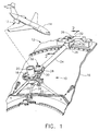
- Figure 1 is an isometric view of an exemplary aircraft engine aft mount including a thrust link having mounting pins therein in accordance with an exemplary embodiment of the present invention.
- Figure 2 is a partly sectional, elevational view of a redundant clevis pin pair at one end of the thrust link illustrated in Figure 1 and taken along line 2-2.
- Figure 3 is a radial sectional view through the clevis pin pair illustrated in Figure 2 mounted in a clevis and taken along line 3-3.
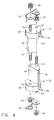
- Figure 4 is an exploded isometric view of the clevis pin pair illustrated in Figure 2.
- Figure 5 is a top view of the clevis pin pair illustrated in Figure 2 and taken along line 5-5.
- Figure 6 is an exploded, isometric view of a clevis pin pair in accordance with an alternate embodiment of the present invention.
- FIG. 1 Illustrated in Figure 1 is an aft engine mount 10 for supporting an aircraft gas turbine engine 12 to the fuselage of an aircraft 14.
- the aft mount 10 is used in conjunction with a forward mount (not shown) for mounting the engine horizontally to the side of the aircraft 14 near its tail.
- the engine 12 is a conventional turbofan gas turbine engine having an outer casing 16, shown in part, to which the forward and aft mounts are connected for supporting the engine to the aircraft fuselage.
- the aft mount includes an aft support 18 in the form of a circular plate which engages the spherical distal end of an airframe fitting 20 fixedly joined in the aircraft.
- the aft mount includes a pair of side links 22 which extend circumferentially from the aft support 18 and generally tangentially to corresponding supporting flanges of the engine casing 16.
- One side link is integrally formed in the aft support 18, and has an opposite end pin mounted to the casing using a conventional spherical bearing, commonly referred to as a uniball, with a mounting pin extending therethrough into the flange clevis.
- the opposite side link is pivotally mounted at one end to the support 18, and is mounted at its opposite end to a corresponding clevis in the casing 16 also using a uniball and mounting pin therethrough.
- the side links 22 carry in-plane horizontal and vertical loads from the engine to the aircraft.
- Thrust loads are carried from the engine to the aircraft using an axially extending thrust link 24 joined at one end to the aft support 18, and joined at its opposite, forward end to a forward yoke or support 26 fixedly joined to the casing 16.
- the thrust link 24 has a pair of clevises 28 integrally formed at opposite ends thereof which engage complementary tongues 30 extending integrally from respective portions of the aft and forward and supports 18,26 in a tongue-and-groove arrangement.
- clevis pins 32 are provided for both of the clevises 28 for pivotally joining the thrust link 24 to the aft and forward supports 18,26 in redundant load paths.
- the illustrated aft mount 10 is conventional in configuration and function, and has enjoyed successful commercial use in this country for many years.
- solid, cylindrical clevis pins are used instead of the improved clevis pins 32, and each conventional pin fails to provide any redundant load path therethrough.
- thrust loads bypass the thrust link 24 and are carried by a failsafe thrust link 34 which is also pin mounted between the aft support 18 and the engine casing 16.
- the main thrust link 24 is active and carries the thrust loads, with the failsafe link 34 being inactive and does not carry any portion of the thrust loads. Any failure of the thrust link 24 itself, or its supported ends, allows the thrust loads to be carried instead by the failsafe link 34 which then becomes active.
- the improved clevis pins 32 illustrated in Figure 1 may simply replace the conventional clevis pins, but provide redundant load paths therethrough in accordance with the present invention illustrated in more particularity in Figures 2 and 3.
- the clevis pins 32 are used in pairs to provide redundant load paths in shear between the tongue 30 and the clevis 28.
- Each pin includes a shank 36 having a semicircular, solid section extending longitudinally or axially between opposite ends thereof for carrying in shear the thrust loads between the thrust link 24 and each of the aft and forward supports 18,26 shown in Figure 1.
- Each clevis pin 32 illustrated in Figure 4 also includes an enlarged head 38 which is preferably cylindrical and is integrally joined to one end of the shank.
- a tip 40 is integrally joined as an extension to the opposite longitudinal end of the respective shanks.
- the pin head 38 is preferably larger in section than the shank to receive in abutment thereagainst the tip 40 from the complementary pin 32.
- the pin tip 40 is preferably no larger in section than the corresponding shank, and is threaded for engaging a complementary retention nut 42.
- each shank 36 includes a flat or land 44 which preferably extends the full diameter and axial length of the semicircular shank.
- the two clevis pins 32 are preferably identical to each other, and the shank flats 44 are positioned to abut each other in a collective circular section illustrated in Figure 3 for providing maximum shear strength capability within the circular envelope of the two abutting shanks 36.
- the abutting flats 44 are disposed along a diameter of the collective circular section along the neutral axis thereof. Since peak shear stress occurs along the neutral axis of a circular section, maximum available area is provided by the respective flats 44 for withstanding the shear loads transferred through the two pins 32 during operation.
- the flats 44 are preferably aligned with the longitudinal or axial axis of the thrust link 24 illustrated in Figures 1 and 2 to maximize the shear strength of the bifurcated pin assemblies joining the two clevises 28 to the respective support tongues 30.
- both the head 38 and tip 40 of each pin are preferably annular and generally axially coextensive with the respective shanks 36.
- Each head 38 preferably includes an integral alignment tab 46 which provides a visual indication having a predetermined or fixed orientation with the respective flats 44 for allowing the shanks 36 to be suitably aligned for maximizing shear strength orientation thereof.
- the alignment tabs 46 may simply be disposed in complementary recesses 48 integrally formed in corresponding bosses in the devises 24 as best illustrated in Figures 2 and 5. In this way, each recess 48 receives a respective tab 46 for aligning the shank flats 44 axially between the thrust link and the supports. In this embodiment, the tab 46 is simply aligned parallel with the flat 44 and is disposed in the recess 48 along the longitudinal axis of the thrust link 24 for effecting proper alignment of the respective shanks 36.
- each clevis 28 is in the form of a U-shaped fork of two parallel flanges having an aperture extending transversely therethrough which preferably contains suitable bushings through which the two cooperating shanks 36 extend upon assembly.
- the support tongue 30 is disposed in the clevis 28 and has a central aperture having mounted therein a spherical bearing or uniball 50 having a central aperture which is coaxially aligned with the clevis apertures for receiving the two shanks 36 therethrough.
- the two abutting shanks 36 having a circular cross section which completely fills the circular cross section of the uniball aperture.
- the two shanks 36 also completely fill the circular sections of the clevis bushings. Accordingly, as thrust load is developed in the engine, it is transferred axially through the support tongue 30 and in turn through both shanks 36, which in turn carry the thrust loads through the two flanges of the clevis 28 and axially through the thrust link 24 to the aft support 18 and finally into the aircraft 14.
- the clevis pin pairs 32 extend through the clevises 28 at the opposite ends of the thrust link 24 to carry thrust in shear between these shanks 36 and the respective support tongues 30.
- each head 38 preferably includes a through aperture 52 laterally offset from the respective shank 36 thereof and sized for receiving axially therethrough a respective one of the tips 40 from the complementary clevis pin 32.
- Each shank tip 40 extends axially through the opposite head aperture 52 which laterally retains or locks together the two shanks 36.
- the shank tips 40 extend through the opposite heads 38 and threadingly receive respective ones of the retention nuts 42 which are tightened to retain together the two clevis pins 32 in axial tension along their shanks between opposite ones of the heads 38.
- the length of the shanks 36 is preferably slightly less than the collective length of the apertures through the clevis bushings and tongue uniball for clamping together these components upon assembly. Tightening the tip nuts 42 places the two shanks 36 in tension for compressing the clevis and tongue in a rigid, high strength assembly.
- the shank tips 40 simultaneously laterally retain together the two shanks in the collective circular configuration in the two clevis pins 32 in a dual element assembly. Or, the shank length may be greater than the collective aperture length to eliminate loads in the shanks themselves.
- each head 38 also includes a threaded stem 54 extending integrally therefrom generally coaxially with the tip 40 of the same clevis pin 32, and in parallel with the tip 40 of the cooperating clevis pin 32 extending through the adjacent head aperture 52.
- a retention clip 56 includes a pair of apertures therein surrounding respective ones of the tip nut 42 and the adjacent stem 54, with an identical clip 56 for the other head.
- a secondary retention nut 58 threadingly engages each of the stems 54 to retain the clip to the respective heads 38, with the clip in turn retaining the respective tip nut 42.
- the stem nut 58 clamps a portion of the clip 56 atop the head 38, with the remaining portion of the clip surrounding the tip nut 42 for preventing removal of the tip nut without firstly removing the retainer clip 56.
- the diameter of the aperture in the clip 56 is suitably smaller than the diameter of the bottom flange of the tip nut 42 which prevents its removal without first removing the clip.
- the clevis pin pair disclosed in the exemplary embodiment of Figures 1-5 provides a dual element redundant load path instead of a single shear pin in the same location. Dual locking of the clevis pin pair is effected using the shank tips 40, head stems 54, and cooperating clips 56 and retention nuts. Since the two clevis pins 32 are preferably identical in configuration, the same pin type may be used for each of the cooperating two pins at each clevis location such as at both ends of the thrust link 24. This identity of parts reduces the overall number of part types for improving manufacture and inventory control.
- the two pin design is compact in envelope and need not be any larger than the conventional unitary shear pin which it may replace.
- the dual element shear pin assembly has substantially equivalent shear strength with that of the single, cylindrical shear pin design. And, most significantly, the dual element clevis pin design provides redundant load paths for increasing the safety of operation of the aft mount.
- Figure 6 illustrates an alternate embodiment of a cooperating pair of substantially identical clevis pins designated 60.
- the shank 36 is again semicircular in section with cooperating flats 44 which collectively define the diametrically bifurcated circular section for redundant load paths.
- the head 62 and shank tip 64 are also semicircular in section, and coextensive with the corresponding semicircular shanks 36.
- the clevis pins 60 illustrated in Figure 6 are basically two identical halves of a single clevis pin or bolt, with the adjoining shank tips 64 being collectively threaded for threadingly receiving a common retention nut 66 thereon.
- the two pins 60 are assembled together and positioned through the respective clevises at both ends of the thrust link 24 illustrated in Figure 1, and retained therein after assembly of the retention nuts 66.
- the second embodiment illustrated in Figure 6 may also include similar alignment tabs 46 extending radially outwardly from the respective heads 62 for providing a visual indication for orienting the shank flats 44 coaxially with the thrust link 24.
- the alignment tabs 46 are aligned parallel with the shank flats 44, whereas in Figure 6, the tabs 46 are aligned perpendicularly thereto. In either case, the tabs 46 may be suitably positioned relative to the thrust link for aligning the shank flats coaxially with the thrust link in the preferred embodiment.
- one, or both, of the clevis pins 60 may also include an assembly tab 68 with a complementary recess 70 in the opposite pin half which ensure proper alignment of the two head halves of the clevis pin pair in an axisymmetrical assembly.
- the second embodiment like the first embodiment, also enjoys the advantages of providing redundant shear load paths through the two shanks 36 in the common apertures of the respective clevises 28 and cooperating tongues 30.
- the cooperating clevis pins may be otherwise configured in complementary shapes for collectively providing a bifurcated cylindrical shank for carrying shear loads between the thrust link 24 and its two adjoining stationary supports.
- the redundant pin pair may be used at other locations in aircraft engine mounts for redundancy as required.
Landscapes
- Engineering & Computer Science (AREA)
- Aviation & Aerospace Engineering (AREA)
- General Engineering & Computer Science (AREA)
- Mechanical Engineering (AREA)
- Pivots And Pivotal Connections (AREA)
Applications Claiming Priority (2)
| Application Number | Priority Date | Filing Date | Title |
|---|---|---|---|
| US09/181,898 US6309131B1 (en) | 1998-10-29 | 1998-10-29 | Redundant clevis pin pair |
| US181898 | 1998-10-29 |
Publications (2)
| Publication Number | Publication Date |
|---|---|
| EP0997653A2 true EP0997653A2 (fr) | 2000-05-03 |
| EP0997653A3 EP0997653A3 (fr) | 2002-11-06 |
Family
ID=22666277
Family Applications (1)
| Application Number | Title | Priority Date | Filing Date |
|---|---|---|---|
| EP99308330A Withdrawn EP0997653A3 (fr) | 1998-10-29 | 1999-10-21 | Vis à oeillet double redondante |
Country Status (3)
| Country | Link |
|---|---|
| US (1) | US6309131B1 (fr) |
| EP (1) | EP0997653A3 (fr) |
| JP (1) | JP2000142591A (fr) |
Cited By (4)
| Publication number | Priority date | Publication date | Assignee | Title |
|---|---|---|---|---|
| EP1593596A1 (fr) * | 2004-05-04 | 2005-11-09 | Snecma | Moteur d'avion avec des moyens de suspension à la structure d'un avion |
| WO2006097484A1 (fr) * | 2005-03-18 | 2006-09-21 | Airbus France | Attache moteur d'un systeme de montage interpose entre un mat d'accrochage et un moteur d'aeronef |
| FR2891253A1 (fr) * | 2005-09-28 | 2007-03-30 | Airbus France Sas | Attache arriere d'un moteur d'aeronef a deux manilles |
| EP3002220A1 (fr) * | 2014-09-30 | 2016-04-06 | Rolls-Royce plc | Dispositif de montage d'un moteur à turbine à gaz |
Families Citing this family (12)
| Publication number | Priority date | Publication date | Assignee | Title |
|---|---|---|---|---|
| US6755005B2 (en) | 2001-08-10 | 2004-06-29 | General Electric Company | Method and apparatus for stiffening and apparatus |
| US7093996B2 (en) * | 2003-04-30 | 2006-08-22 | General Electric Company | Methods and apparatus for mounting a gas turbine engine |
| FR2873987B1 (fr) * | 2004-08-05 | 2006-11-24 | Airbus France Sas | Ensemble moteur pour aeronef |
| US7914226B2 (en) * | 2005-08-17 | 2011-03-29 | Miller Uk Limited | Non-removable safety pin |
| US20070056292A1 (en) * | 2005-09-14 | 2007-03-15 | Honeywell International, Inc. | Auxiliary power unit case flange to cone bolt adapter |
| FR2891254B1 (fr) * | 2005-09-29 | 2007-10-26 | Airbus France Sas | Ensemble moteur pour aeronef |
| FR2923459B1 (fr) * | 2007-11-09 | 2010-05-21 | Snecma | Moyen de blocage en rotation d'un axe supportant un organe de suspension de turbomoteur |
| US8453429B2 (en) * | 2009-06-30 | 2013-06-04 | General Electric Company | System and method for assembling a thrust reverser for a gas turbine propulsion system |
| US8348191B2 (en) * | 2010-07-14 | 2013-01-08 | Spirit Aerosystems, Inc. | Fail-safe aircraft engine mounting apparatus |
| US9227734B2 (en) | 2012-08-31 | 2016-01-05 | United Technologies Corporation | Secondary load path for gas turbine engine |
| JP6137846B2 (ja) * | 2013-01-25 | 2017-05-31 | 三菱航空機株式会社 | パイロンと翼を連結するリンク部材、航空機のパイロンおよび航空機 |
| DE102018129535A1 (de) * | 2018-11-23 | 2020-05-28 | Airbus Operations Gmbh | Bauteil zum Halten oder Stützen einer Komponente |
Family Cites Families (25)
| Publication number | Priority date | Publication date | Assignee | Title |
|---|---|---|---|---|
| US413700A (en) * | 1889-10-29 | Device for pulling cross-heads from piston-rods | ||
| US930232A (en) * | 1908-10-16 | 1909-08-03 | Walter Pierson Rodman | Bearing. |
| GB270504A (en) * | 1926-06-03 | 1927-05-12 | Alfred Austin Whitley | Improvements in pins for use in connecting the links of clips of stentering machines |
| GB457767A (en) * | 1935-05-27 | 1936-11-27 | Frederick Arthur Manning | Improvements in means for detachably attaching metal plates or other similar flat sectional members together or to other members |
| US2292128A (en) * | 1942-05-27 | 1942-08-04 | King James | Connecting pin |
| FR962161A (fr) * | 1944-05-13 | 1950-06-02 | ||
| BE479932A (fr) * | 1945-04-09 | |||
| US2519464A (en) * | 1947-02-03 | 1950-08-22 | Miner Inc W H | Center pin for body and truck bolsters |
| US3245705A (en) * | 1962-10-01 | 1966-04-12 | Caterpillar Tractor Co | Rod and piston connection |
| US3420136A (en) * | 1967-09-19 | 1969-01-07 | Jet Avion Corp | Fastening means |
| US3549186A (en) * | 1969-06-06 | 1970-12-22 | Chicago Bridge & Iron Co | Quick opening closure using split shear studs |
| US3923349A (en) * | 1973-06-25 | 1975-12-02 | Lord Corp | Universal bearing support |
| US3922946A (en) * | 1973-12-26 | 1975-12-02 | Dayton Sure Grip & Shore Co | Split bolt |
| DE2541105C3 (de) * | 1975-09-15 | 1978-07-27 | Springfix-Befestigungstechnik Gmbh, 7335 Salach | Befestigungselement |
| US4478546A (en) * | 1981-12-21 | 1984-10-23 | Mercer Mark J | Quick insertion and release bolt system |
| US4786202A (en) * | 1985-02-12 | 1988-11-22 | The United States Of America As Represented By The Secretary Of The Air Force | Dual load path pin clevis joint |
| US5061134A (en) * | 1990-06-27 | 1991-10-29 | Oh Jung H | Divided bolt fastening device |
| US5320307A (en) * | 1992-03-25 | 1994-06-14 | General Electric Company | Aircraft engine thrust mount |
| US5277382A (en) * | 1992-10-13 | 1994-01-11 | General Electric Company | Aircraft engine forward mount |
| US5303880A (en) * | 1992-10-28 | 1994-04-19 | General Electric Company | Aircraft engine pin mount |
| US5725181A (en) * | 1996-05-01 | 1998-03-10 | The Boeing Company | Aircraft engine thrust mount |
| FR2755944B1 (fr) * | 1996-11-21 | 1998-12-24 | Snecma | Suspension avant redondante pour turbomachine |
| US5873547A (en) * | 1997-05-20 | 1999-02-23 | The Boeing Company | Aircraft engine thrust mount |
| US5865557A (en) * | 1997-07-14 | 1999-02-02 | Harnischfeger Corporation | Clevis with improved pin locking assembly |
| US5921500A (en) * | 1997-10-08 | 1999-07-13 | General Electric Company | Integrated failsafe engine mount |
-
1998
- 1998-10-29 US US09/181,898 patent/US6309131B1/en not_active Expired - Fee Related
-
1999
- 1999-10-21 EP EP99308330A patent/EP0997653A3/fr not_active Withdrawn
- 1999-10-27 JP JP11304784A patent/JP2000142591A/ja not_active Withdrawn
Cited By (12)
| Publication number | Priority date | Publication date | Assignee | Title |
|---|---|---|---|---|
| EP1593596A1 (fr) * | 2004-05-04 | 2005-11-09 | Snecma | Moteur d'avion avec des moyens de suspension à la structure d'un avion |
| FR2869874A1 (fr) * | 2004-05-04 | 2005-11-11 | Snecma Moteurs Sa | Moteur d'avion avec des moyens de suspension a la structure d'un avion |
| US7267301B2 (en) | 2004-05-04 | 2007-09-11 | Snecma Moteurs | Aircraft engine with means of suspension from the structure of an aircraft |
| RU2372256C2 (ru) * | 2004-05-04 | 2009-11-10 | Снекма | Авиационный двигатель, содержащий средства подвески к конструкции самолета |
| WO2006097484A1 (fr) * | 2005-03-18 | 2006-09-21 | Airbus France | Attache moteur d'un systeme de montage interpose entre un mat d'accrochage et un moteur d'aeronef |
| FR2883256A1 (fr) * | 2005-03-18 | 2006-09-22 | Airbus France Sas | Attache moteur d'un systeme de montage interpose entre un mat d'accrochage et un moteur d'aeronef |
| US8336812B2 (en) | 2005-03-18 | 2012-12-25 | Airbus Operations Sas | Engine attachment for an assembly system mounted between an attachment strut and an aircraft engine |
| FR2891253A1 (fr) * | 2005-09-28 | 2007-03-30 | Airbus France Sas | Attache arriere d'un moteur d'aeronef a deux manilles |
| WO2007036515A1 (fr) * | 2005-09-28 | 2007-04-05 | Airbus France | Attache arrière d'un moteur d'aéronef à deux manilles |
| US7909302B2 (en) | 2005-09-28 | 2011-03-22 | Airbus France | Two-shackle aircraft engine attachment |
| EP3002220A1 (fr) * | 2014-09-30 | 2016-04-06 | Rolls-Royce plc | Dispositif de montage d'un moteur à turbine à gaz |
| US10018077B2 (en) | 2014-09-30 | 2018-07-10 | Rolls-Royce Plc | Gas turbine engine mounting arrangement |
Also Published As
| Publication number | Publication date |
|---|---|
| JP2000142591A (ja) | 2000-05-23 |
| US6309131B1 (en) | 2001-10-30 |
| EP0997653A3 (fr) | 2002-11-06 |
Similar Documents
| Publication | Publication Date | Title |
|---|---|---|
| US6309131B1 (en) | Redundant clevis pin pair | |
| US5927644A (en) | Double failsafe engine mount | |
| US5725181A (en) | Aircraft engine thrust mount | |
| US5921500A (en) | Integrated failsafe engine mount | |
| RU2167788C2 (ru) | Отказобезопасная рама для подвески двигателя | |
| US8985509B2 (en) | Assembly for mounting a turbine engine to a pylon | |
| EP0564126B1 (fr) | Montage de reprise de poussée d'un moteur sur un avion | |
| US6474597B1 (en) | Gas turbine engine mounting arrangement | |
| US5860623A (en) | Three link failsafe engine mount | |
| US5620154A (en) | Three link failsafe engine mount | |
| EP1375348B1 (fr) | Support de turbine d'avion avec une seule biellette de poussée | |
| US5873547A (en) | Aircraft engine thrust mount | |
| US4786202A (en) | Dual load path pin clevis joint | |
| US20080067286A1 (en) | Aircraft engine mounting device attachment arrangement | |
| US20140084129A1 (en) | Assembly for mounting a turbine engine case to a pylon | |
| US7438262B2 (en) | Redundant gas turbine engine mounting arrangement | |
| US20240417090A1 (en) | Device for coupling a propulsion system to an engine pylon of an aircraft, and corresponding aircraft | |
| US7156343B2 (en) | Mounting system inserted between an aircraft engine and a rigid structure of an attachment strut fixed under a wing of this aircraft | |
| US11066860B1 (en) | Hinged assembly with fail-safe hinge pin | |
| EP3486435B1 (fr) | Joint de fusible comportant une broche de fusible fenêtrée | |
| EP2841339B1 (fr) | Fixation redondante d'un carter d'échappement de turbine | |
| US20250206448A1 (en) | Suspension assembly for a turbine engine | |
| US20250010997A1 (en) | Assembly of an attachment pylon with an aircraft engine |
Legal Events
| Date | Code | Title | Description |
|---|---|---|---|
| PUAI | Public reference made under article 153(3) epc to a published international application that has entered the european phase |
Free format text: ORIGINAL CODE: 0009012 |
|
| AK | Designated contracting states |
Kind code of ref document: A2 Designated state(s): AT BE CH CY DE DK ES FI FR GB GR IE IT LI LU MC NL PT SE |
|
| AX | Request for extension of the european patent |
Free format text: AL;LT;LV;MK;RO;SI |
|
| PUAL | Search report despatched |
Free format text: ORIGINAL CODE: 0009013 |
|
| AK | Designated contracting states |
Kind code of ref document: A3 Designated state(s): AT BE CH CY DE DK ES FI FR GB GR IE IT LI LU MC NL PT SE |
|
| AX | Request for extension of the european patent |
Free format text: AL;LT;LV;MK;RO;SI |
|
| RIC1 | Information provided on ipc code assigned before grant |
Free format text: 7F 16C 11/04 A, 7B 64D 27/26 B |
|
| 17P | Request for examination filed |
Effective date: 20030506 |
|
| AKX | Designation fees paid |
Designated state(s): DE FR GB |
|
| 17Q | First examination report despatched |
Effective date: 20030620 |
|
| STAA | Information on the status of an ep patent application or granted ep patent |
Free format text: STATUS: THE APPLICATION IS DEEMED TO BE WITHDRAWN |
|
| 18D | Application deemed to be withdrawn |
Effective date: 20031231 |