EP0997664A1 - Antriebsvorrichtung für ein bewegbares Teil, insbesondere ein Seitenausstellfenster eines Fahrzeuges - Google Patents
Antriebsvorrichtung für ein bewegbares Teil, insbesondere ein Seitenausstellfenster eines Fahrzeuges Download PDFInfo
- Publication number
- EP0997664A1 EP0997664A1 EP99120036A EP99120036A EP0997664A1 EP 0997664 A1 EP0997664 A1 EP 0997664A1 EP 99120036 A EP99120036 A EP 99120036A EP 99120036 A EP99120036 A EP 99120036A EP 0997664 A1 EP0997664 A1 EP 0997664A1
- Authority
- EP
- European Patent Office
- Prior art keywords
- drive device
- ball
- threads
- drive
- threaded piece
- Prior art date
- Legal status (The legal status is an assumption and is not a legal conclusion. Google has not performed a legal analysis and makes no representation as to the accuracy of the status listed.)
- Granted
Links
Images

Classifications
-
- F—MECHANICAL ENGINEERING; LIGHTING; HEATING; WEAPONS; BLASTING
- F16—ENGINEERING ELEMENTS AND UNITS; GENERAL MEASURES FOR PRODUCING AND MAINTAINING EFFECTIVE FUNCTIONING OF MACHINES OR INSTALLATIONS; THERMAL INSULATION IN GENERAL
- F16C—SHAFTS; FLEXIBLE SHAFTS; ELEMENTS OR CRANKSHAFT MECHANISMS; ROTARY BODIES OTHER THAN GEARING ELEMENTS; BEARINGS
- F16C11/00—Pivots; Pivotal connections
- F16C11/04—Pivotal connections
- F16C11/06—Ball-joints; Other joints having more than one degree of angular freedom, i.e. universal joints
- F16C11/0604—Construction of the male part
-
- E—FIXED CONSTRUCTIONS
- E05—LOCKS; KEYS; WINDOW OR DOOR FITTINGS; SAFES
- E05F—DEVICES FOR MOVING WINGS INTO OPEN OR CLOSED POSITION; CHECKS FOR WINGS; WING FITTINGS NOT OTHERWISE PROVIDED FOR, CONCERNED WITH THE FUNCTIONING OF THE WING
- E05F15/00—Power-operated mechanisms for wings
- E05F15/60—Power-operated mechanisms for wings using electrical actuators
- E05F15/603—Power-operated mechanisms for wings using electrical actuators using rotary electromotors
- E05F15/611—Power-operated mechanisms for wings using electrical actuators using rotary electromotors for swinging wings
- E05F15/616—Power-operated mechanisms for wings using electrical actuators using rotary electromotors for swinging wings operated by push-pull mechanisms
- E05F15/622—Power-operated mechanisms for wings using electrical actuators using rotary electromotors for swinging wings operated by push-pull mechanisms using screw-and-nut mechanisms
-
- F—MECHANICAL ENGINEERING; LIGHTING; HEATING; WEAPONS; BLASTING
- F16—ENGINEERING ELEMENTS AND UNITS; GENERAL MEASURES FOR PRODUCING AND MAINTAINING EFFECTIVE FUNCTIONING OF MACHINES OR INSTALLATIONS; THERMAL INSULATION IN GENERAL
- F16C—SHAFTS; FLEXIBLE SHAFTS; ELEMENTS OR CRANKSHAFT MECHANISMS; ROTARY BODIES OTHER THAN GEARING ELEMENTS; BEARINGS
- F16C11/00—Pivots; Pivotal connections
- F16C11/04—Pivotal connections
- F16C11/06—Ball-joints; Other joints having more than one degree of angular freedom, i.e. universal joints
- F16C11/0619—Ball-joints; Other joints having more than one degree of angular freedom, i.e. universal joints the female part comprising a blind socket receiving the male part
- F16C11/0623—Construction or details of the socket member
- F16C11/0628—Construction or details of the socket member with linings
-
- E—FIXED CONSTRUCTIONS
- E05—LOCKS; KEYS; WINDOW OR DOOR FITTINGS; SAFES
- E05Y—INDEXING SCHEME ASSOCIATED WITH SUBCLASSES E05D AND E05F, RELATING TO CONSTRUCTION ELEMENTS, ELECTRIC CONTROL, POWER SUPPLY, POWER SIGNAL OR TRANSMISSION, USER INTERFACES, MOUNTING OR COUPLING, DETAILS, ACCESSORIES, AUXILIARY OPERATIONS NOT OTHERWISE PROVIDED FOR, APPLICATION THEREOF
- E05Y2201/00—Constructional elements; Accessories therefor
- E05Y2201/60—Suspension or transmission members; Accessories therefor
- E05Y2201/622—Suspension or transmission members elements
- E05Y2201/628—Bearings
- E05Y2201/636—Universal or ball joints
-
- E—FIXED CONSTRUCTIONS
- E05—LOCKS; KEYS; WINDOW OR DOOR FITTINGS; SAFES
- E05Y—INDEXING SCHEME ASSOCIATED WITH SUBCLASSES E05D AND E05F, RELATING TO CONSTRUCTION ELEMENTS, ELECTRIC CONTROL, POWER SUPPLY, POWER SIGNAL OR TRANSMISSION, USER INTERFACES, MOUNTING OR COUPLING, DETAILS, ACCESSORIES, AUXILIARY OPERATIONS NOT OTHERWISE PROVIDED FOR, APPLICATION THEREOF
- E05Y2800/00—Details, accessories and auxiliary operations not otherwise provided for
- E05Y2800/40—Physical or chemical protection
- E05Y2800/422—Physical or chemical protection against vibration or noise
-
- E—FIXED CONSTRUCTIONS
- E05—LOCKS; KEYS; WINDOW OR DOOR FITTINGS; SAFES
- E05Y—INDEXING SCHEME ASSOCIATED WITH SUBCLASSES E05D AND E05F, RELATING TO CONSTRUCTION ELEMENTS, ELECTRIC CONTROL, POWER SUPPLY, POWER SIGNAL OR TRANSMISSION, USER INTERFACES, MOUNTING OR COUPLING, DETAILS, ACCESSORIES, AUXILIARY OPERATIONS NOT OTHERWISE PROVIDED FOR, APPLICATION THEREOF
- E05Y2900/00—Application of doors, windows, wings or fittings thereof
- E05Y2900/50—Application of doors, windows, wings or fittings thereof for vehicles
- E05Y2900/53—Type of wing
- E05Y2900/55—Windows
-
- Y—GENERAL TAGGING OF NEW TECHNOLOGICAL DEVELOPMENTS; GENERAL TAGGING OF CROSS-SECTIONAL TECHNOLOGIES SPANNING OVER SEVERAL SECTIONS OF THE IPC; TECHNICAL SUBJECTS COVERED BY FORMER USPC CROSS-REFERENCE ART COLLECTIONS [XRACs] AND DIGESTS
- Y10—TECHNICAL SUBJECTS COVERED BY FORMER USPC
- Y10T—TECHNICAL SUBJECTS COVERED BY FORMER US CLASSIFICATION
- Y10T403/00—Joints and connections
- Y10T403/32—Articulated members
- Y10T403/32606—Pivoted
- Y10T403/32631—Universal ball and socket
- Y10T403/32681—Composite ball
- Y10T403/32696—Nonmetallic part
-
- Y—GENERAL TAGGING OF NEW TECHNOLOGICAL DEVELOPMENTS; GENERAL TAGGING OF CROSS-SECTIONAL TECHNOLOGIES SPANNING OVER SEVERAL SECTIONS OF THE IPC; TECHNICAL SUBJECTS COVERED BY FORMER USPC CROSS-REFERENCE ART COLLECTIONS [XRACs] AND DIGESTS
- Y10—TECHNICAL SUBJECTS COVERED BY FORMER USPC
- Y10T—TECHNICAL SUBJECTS COVERED BY FORMER US CLASSIFICATION
- Y10T74/00—Machine element or mechanism
- Y10T74/18—Mechanical movements
- Y10T74/18568—Reciprocating or oscillating to or from alternating rotary
- Y10T74/18576—Reciprocating or oscillating to or from alternating rotary including screw and nut
- Y10T74/18728—Backlash
-
- Y—GENERAL TAGGING OF NEW TECHNOLOGICAL DEVELOPMENTS; GENERAL TAGGING OF CROSS-SECTIONAL TECHNOLOGIES SPANNING OVER SEVERAL SECTIONS OF THE IPC; TECHNICAL SUBJECTS COVERED BY FORMER USPC CROSS-REFERENCE ART COLLECTIONS [XRACs] AND DIGESTS
- Y10—TECHNICAL SUBJECTS COVERED BY FORMER USPC
- Y10T—TECHNICAL SUBJECTS COVERED BY FORMER US CLASSIFICATION
- Y10T74/00—Machine element or mechanism
- Y10T74/19—Gearing
- Y10T74/19642—Directly cooperating gears
- Y10T74/19698—Spiral
- Y10T74/19702—Screw and nut
- Y10T74/19721—Thread geometry
Definitions
- the invention relates to a drive device for a movable part, in particular a side opening window of a vehicle, with an actuator that is connected to the movable part via connecting elements, according to the features of the preamble of claim 1.
- the actuator is designed as an electric motor that is geared to a Threaded rod acts, the threaded rod being connected to a Bowden cable is.
- the Bowden cable is moved linearly by turning the threaded rod and thus causes the side opening window to be opened or closed becomes.
- This arrangement has the disadvantage that it is complex because the actuator in an area that is far from the location which engages the connecting element on the side opening window. Out of it results in a high installation effort.
- the invention is therefore based on the object of a drive device for a movable part, in particular a side opening window of a vehicle, to improve such that vibrations of the components involved largely be prevented or completely excluded.
- individual threads at least one Threaded piece are designed such that they are in the associated Apply threads to the other threaded part under the action of force.
- the individual threaded pieces are usually injection molded made of plastic, this process is subject to certain tolerances.
- the invention now makes use of the fact that individual threads of a threaded piece, for example, are thicker than that remaining threads, while the threads of the other threaded piece have a uniform shape and dimensions. This will achieved that the thicker individual threads under the action of force in the associated threads of the other threaded piece apply, so that the tolerances arising during manufacture are balanced and a still permissible stiffness by that Actuator can be easily overcome, is accepted to effectively prevent the tendency to vibrate.
- individual threads are compared to the remaining threads are curved in the circumferential direction.
- it can be a simple bow, but also an extreme one elongated S - bow, so that the flanks of the individual threads partly on the threads of the associated threaded piece below Apply force. Again, the required low stiffness achieved to compensate for tolerances.
- individual threads have at least partially a slot in the circumferential direction. These individual threads are then thicker than the other threads, a certain flexibility is achieved through the slot, since the through the slot separated flanks of a thread against the Press the thread of the associated threaded piece.
- individual threads are from a position specified by the associated threaded piece different position arranged. This displacement from the target position in the circumferential direction out also causes a flank of a thread against the flank of the thread of the associated threaded piece presses, so that here again the effect is achieved that tolerances are compensated become.
- a measure or a combination takes place in a particularly advantageous manner of measures on a threaded piece application that as an external thread is formed since an external thread is composed by a shape of two and molds that can be separated again are produced by injection molding, while an internal thread with a shape having an external thread is produced, this core in the form with internal thread after Manufacturing process is turned out.
- the threaded piece will also with the internal thread of two and more mold halves, which after manufacture can be separated, manufactured, find the measures described also for this threaded piece.
- a stored in a ball socket of the ball joint Ball head or the ball socket with resilient means is provided.
- the ball joint is made of plastic, which for example, is produced by injection molding. This leads to tolerances, so that the ball head mounted in the ball socket with a certain Move the game relative to the ball socket due to these tolerances can.
- These tolerances are in accordance with the invention with the Elastic compliant means eliminated, so that although the ball head in the Ball socket can still move (possibly a little stiff), however a positive connection has arisen, so that there is no longer any room for vibrations Available. It also reduces the transmission of structure-borne noise of the actuator (engine noise) on the side opening window prevented.
- the ball head has at least one circumferential one Groove that receives a rubber ring. This can be done in a simple manner and Such a ball head can be produced, the circumferential groove is either introduced during the manufacturing process or after manufacturing of the ball head is introduced.
- the rubber ring is for Example of a so-called O-ring that is inexpensive and in a variety of different dimensions (diameters and thicknesses) is available.
- the drive device according to the invention can also be inexpensive getting produced.
- the ball head has two parallel ones from the center out arranged grooves, in each of which a rubber ring is inserted. Because there are two circumferential surfaces available with which the surface the rubber ring can rest on the inner surface of the ball socket ensures that with every movement at least one surface of a Rubber ring rests on the inner surface of the ball socket and thus the disturbing noises can be effectively avoided. This is especially so required if the ball-and-socket joint is curved in its path of movement Movement. A web resulting between the grooves serves the power transmission during pull and push movements.
- the ball head can also consist of two correspondingly grooved spherical head halves. If the rubber rings are pressed together during pulling and pushing movements, the surfaces of the ball head halves are used for power transmission come into positive contact with the ball socket.
- the ball head is at least partially with a elastic resilient layer covered.
- a elastically compliant Layer can, for example, be drawn over the ball head after its production be, it is also conceivable to immerse the ball head in a corresponding liquid with such a layer, which is then in passes into a solid state. Even with such a layer ensures that the tolerance between the ball socket and the ball head of the ball joint is eliminated.
- the same effect occurs, if or only the ball socket on yours At least partially covered on the inside with an elastically flexible layer is. It should also be mentioned that it is also conceivable that the inside the ball socket is provided with at least one circumferential groove into which a rubber ring is inserted, but it is advisable to do so Take measures only with the ball head, because the manufacturing and assembly process is easier here.
- the ball joint is between the connecting element and arranged the movable part.
- the connecting element it is for example the already known Bowden cable or a connecting rod or, if necessary, a combination of the both mentioned elements. Since the side opening window is articulated on the Chassis arranged and the ball joint at a distance from this articulation point is arranged, the ball joint performs when the side opening window moves from the closed to the open position an approximately arcuate Track that over the ball joint with largely linear movement of the connecting element is made possible. This means that the end of the Connecting element (the connecting rod) a linear movement path describes that over the ball joint in an arcuate trajectory is implemented.
- the drive device according to the invention is based on a Described embodiment and explained with reference to the figures, wherein the inventive concept is not limited to this embodiment.
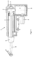
- FIG. 1 shows an opening window drive 1, the so-called linear drive is trained.
- the opening window drive 1 has an electric motor as an actuator 2, which drives a drive shaft 4 via a reduction gear 3.
- This drive shaft 4 has a gear wheel 5 with external teeth on, wherein the gear 5 from one on the motor shaft of the electric motor 2nd arranged, not shown worm wheel is driven.
- the drive shaft 4, which has an external thread extends longitudinally within a drive tube 6, the drive tube 6 with a provide the internal thread corresponding to the external thread of the drive shaft 4 is. Bearings for the drive shaft 4 and the drive tube 6 are indeed available, but not shown for clarity.
- the opening window drive 1 also has a housing 8 in which the drive elements are accommodated.
- the housing 8 can for the purpose of noise reduction be provided with an insulation layer, especially on the inside.
- On the housing 8 or made in one piece with this is a plug 9, via which the electric motor 2 is controlled. If necessary, too Position signals transmitted via this connector 9.
- Fasteners are also 10 available with which the hinged window drive 1 in one part of the vehicle can be attached. The arrangement and training of the Fastening means 10 depends on the installation space of the opening window drive 1, which is thus easily installed as a module and via the plug 9 in Can be put into operation.
- a connecting rod 11 projects out of the cover 7, which is the Cover 7 facing away from the connecting rod 11 a ball head 12 having.
- the connecting rod 11 and the ball head 12 are advantageous as a one-piece turned part (for example aluminum) or as a plastic part manufactured, but can also form two components, for which purpose the ball head 12 connected to the connecting rod 11 (for example by gluing or clipping).
- the other end of the connecting rod is also advantageous 11 connected to a ball head inside the cover 7.
- the spherical head 12 shown in Figure 1 has two arranged from the center Rubber rings 13, which are inserted into grooves.
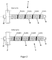
- FIG. 2 shows detailed views of the drive shaft 4.
- This has an elongated Threaded piece 14, which is designed as an external thread.
- On the ends of the drive shaft 4 are bearing ends 15, with which the Drive shaft 4, for example, in the housing 8 or in the drive tube 6 is stored.
- the threaded piece 14 has teeth 16 which are the external thread form. Due to the filled threads of the (for example) third, the eighth, the thirteenth and the eighteenth tooth is indicated that this Teeth on the top, that is, around half the circumference of the threaded piece 14, are thicker than the other teeth 16.
- the drive shaft 4 ensures that it is somewhat stiff in the drive tube 6 moves and always a frictional connection between the drive shaft 4th and the drive tube 6 is given, so that no longitudinal movement of the drive tube 6 or the drive shaft 4 in the longitudinal direction of tolerances is possible.
- the thickening is chosen so that a straight required stiffness is achieved by the electric motor 2 easily can be overridden, but is not so large that the individual Teeth would be subject to unnecessary wear. That's why it's on the place conceivable that lubricant especially suitable for plastic between the threads are given.
- the Surface of the drive tube 6 with resilient means for example a felt that is glued on to provide tolerances between the drive tube 6 and the housing 8 during a longitudinal movement of the drive tube 6 balance.
- the teeth 16 have a thickness (width) that with reference number 17 is provided. At least one of the teeth, the thicker is formed as the remaining teeth (this width is here with the reference number 18 provided), has a slot 19, this slot 19 in interaction compressed with the threads of the drive tube 6 can be compensated so that due to this spring-like effect tolerances and vibrations are avoided.
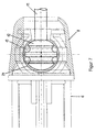
- FIG 5 shows one end of the drive tube 6 with the connecting rod installed 11 and without a cover 7.
- This cover 7 essentially represents a protective cover to prevent that the underneath Ball joint and the innards of the opening window drive 1 dirty become.
- a cover of the ball joint its Ball head 12 is shown in Figure 1, with a correspondingly designed Coverage possible.
- One end of the drive tube 6 has unspecified Projections on the cover 7 after placing it in its corresponding Engage recesses (or vice versa: projections on the cover 7 and corresponding depressions at one end of the drive tube 6), so that the cover 7 by means of a positive fit on one End of the drive tube 6 is fixed.
- a ball socket for the ball head 12 21 provided at this one end of the drive tube 6 .
- part of the drive tube can also be used 6 in connection with a part of the cover 7 or the cover 7 alone form the ball socket 21, so that after inserting the ball head 12 in the part of the ball socket 21 of the drive tube 6, the cover 7 is and thus the connecting rod 11 is movably fixed.
- the same process can be carried out on the other side of the connecting rod 11 take place, with part of the ball socket on the side opening window, not shown is attached and a corresponding cover over the ball head 12 of Figure 1 is pushed over.
- the opening window drive 1 is preferably done before Fixed installation of the opening window drive 1 so that the drive tube 6 is brought into a position which corresponds to the closed position of the side window corresponds; then the outer ball head 12 with the ball socket connected to the side opening window via the cover and then only the housing 8 of the opening window drive 1 with the fastening means 10 attached to the body or another part of the vehicle.
- the side opening window can then from its closed position to an open position or a Intermediate position are brought, in particular the fully open Position by block operation of the electric motor 2 or by a limit switch, which is preferably integrated in the housing 8 and depending on this, the power supply to the electric motor 2 is switched off becomes.
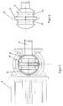
- FIG. 6 shows a section through a spherical head 12, it being possible to see how two grooves 22 in the shape of a groove and extending over the circumference of the ball head 12 extending to receive the rubber rings 13 from the center are.
- the use of two grooves 22 and two inserted accordingly Rubber rings 13 is required to ensure that at least always a surface of a rubber ring 13 with the corresponding, not shown here Inner surface of the ball socket, which is in particular part of the cover 7, stays in touch and through which there is one between the two Grooves 14 adjusting web 23 a transmission of the forces from the connecting rod 11 on the ball socket, not shown, on the side opening window is attached, is given, especially when the side opening window moves from its open position to its closed position high tensile forces have to be applied.
- the center of the ball head 12 (respectively of the two halves of the ball head) need not be at the intersection of the figure 6 shown horizontal dashed line and the center line 24 of the Web 23 are located, but can differ.
- the center of the left half of the spherical head 12 in the right small square and the center of the right half of the spherical head 12 are in the left small square.
- the center of the left half of the spherical head 12 in the left small square and the center of the right half of the ball head 12 are in the right small square.
- Figure 7 shows one end of the drive tube 6 with the connecting rod installed 11 and with cover 7 in place.
Landscapes
- Engineering & Computer Science (AREA)
- General Engineering & Computer Science (AREA)
- Mechanical Engineering (AREA)
- Power-Operated Mechanisms For Wings (AREA)
- Window Of Vehicle (AREA)
- Transmission Devices (AREA)
Abstract
Description
- Figur 1:
- einen Ausstellfensterantrieb,
- Figur 2:
- Detailansichten einer Antriebswelle,
- Figuren 3 und 4:
- verschiedene Zahnformen,
- Figur 5:
- ein Ende eines Antriebsrohres mit montierter Verbindungsstange und ohne Abdeckung,
- Figur 6:
- eine Detailansicht eines Kugelgelenkes,
- Figur 7:
- ein Ende eines Antriebsrohres mit montierter Verbindungsstange und Abdeckung.
- 1.
- Ausstellfensterantrieb
- 2.
- Elektromotor
- 3.
- Untersetzungsgetriebe
- 4.
- Antriebswelle (mit Außengewinde)
- 5.
- Zahnrad
- 6.
- Antriebsrohr (mit Innengewinde)
- 7.
- Abdeckung
- 8.
- Gehäuse
- 9.
- Stecker
- 10.
- Befestigungsmittel
- 11.
- Verbindungsstange
- 12.
- Kugelkopf
- 13.
- Gummiring
- 14.
- Gewindestück
- 15.
- Lagerende
- 16.
- Zähne
- 17.
- Breite
- 18.
- größere Breite
- 19.
- Schlitz
- 20.
- ein Zahn
- 21.
- Kugelpfanne
- 22.
- Nuten
- 23.
- Steg
- 24.
- Mittellinie
Claims (14)
- Antriebsvorrichtung für ein bewegbares Teil, insbesondere ein Seitenausstellfenster eines Fahrzeuges, mit einem Stellantrieb und einem von dem Stellantrieb angetriebenen Gewindestück, daß mit einem zugehörigen Gewindestück kämmt, wobei das zugehörige Gewindestück das Teil bewegt, dadurch gekennzeichnet, daß einzelne Gewindegänge zumindest eines Gewindestückes (14) derart ausgebildet sind, daß sie in den jeweils zugehörigen Gewindegängen des anderen Gewindestückes unter Krafteinwirkung anliegen.
- Antriebsvorrichtung nach Anspruch 1, dadurch gekennzeichnet, daß einzelne Gewindegänge gegenüber den übrigen Gewindegängen dicker ausgebildet sind.
- Antriebsvorrichtung nach Anspruch 1 oder 2, dadurch gekennzeichnet, daß einzelne Gewindegänge gegenüber den übrigen Gewindegängen in Umfangsrichtung gebogen ausgebildet sind.
- Antriebsvorrichtung nach einem der Ansprüche 1 bis 3, dadurch gekennzeichnet, daß einzelne Gewindegänge zumindest teilweise in Umfangsrichtung einen Schlitz aufweisen.
- Antriebsvorrichtung nach einem der vorhergehenden Ansprüche 1 bis 4, dadurch gekennzeichnet, daß einzelne Gewindegänge aus einer von der durch das zugehörige Gewindestück vorgegebenen Lage abweichenden Lage angeordnet sind.
- Antriebsvorrichtung nach einem der vorhergehenden Ansprüche, wobei der Stellantrieb über wenigstens ein Verbindungselement und ein Kugelgelenk mit dem bewegbaren Teil verbunden ist, dadurch gekennzeichnet, daß ein in einer Kugelpfanne des Kugelgelenkes gelagerter Kugelkopf (12) oder die Kugelpfanne mit elastisch nachgiebigen Mitteln versehen ist.
- Antriebsvorrichtung nach Anspruch 6, dadurch gekennzeichnet, daß der Kugelkopf (12) wenigstens eine umlaufende Nut aufweist, die einen Gummiring (13) aufnimmt.
- Antriebsvorrichtung nach Anspruch 6, dadurch gekennzeichnet, daß der Kugelkopf (12) zwei parallele, aus der Mitte heraus angeordnete Nuten (22) aufweist, in denen jeweils ein Gummiring (13) eingelegt ist.
- Antriebsvorrichtung nach Anspruch 6, dadurch gekennzeichnet, daß der Kugelkopf (12) zumindest teilweise mit einer elastisch nachgiebigen Schicht überzogen ist.
- Antriebsvorrichtung nach Anspruch 6, dadurch gekennzeichnet, daß die Kugelpfanne auf ihrer Innenseite zumindest teilweise mit einer elastisch nachgiebigen Schicht überzogen ist.
- Antriebsvorrichtung nach einem der vorhergehenden Ansprüche, dadurch gekennzeichnet, daß das Kugelgelenk zwischen dem Verbindungselement (Verbindungsstange 11) und dem bewegbaren Teil angeordnet ist.
- Antriebsvorrichtung nach einem der vorhergehenden Ansprüche, dadurch gekennzeichnet, daß das Kugelelement zwischen dem Verbindungselement (Verbindungsstange 11) und dem Stellantrieb angeordnet ist.
- Antriebsvorrichtung nach Anspruch 11 und 12, gekennzeichnet durch die Kombination der Merkmale der Ansprüche 11 und 12.
- Antriebsvorrichtung nach einem der vorhergehenden Ansprüche, dadurch gekennzeichnet, daß die Antriebsvorrichtung als Linearantrieb ausgebildet ist.
Applications Claiming Priority (2)
| Application Number | Priority Date | Filing Date | Title |
|---|---|---|---|
| DE19849245 | 1998-10-26 | ||
| DE19849245A DE19849245C1 (de) | 1998-10-26 | 1998-10-26 | Antriebsvorrichtung für ein bewegbares Teil, insbesondere ein Seitenausstellfenster eines Fahrzeuges |
Publications (2)
| Publication Number | Publication Date |
|---|---|
| EP0997664A1 true EP0997664A1 (de) | 2000-05-03 |
| EP0997664B1 EP0997664B1 (de) | 2003-01-02 |
Family
ID=7885630
Family Applications (1)
| Application Number | Title | Priority Date | Filing Date |
|---|---|---|---|
| EP99120036A Expired - Lifetime EP0997664B1 (de) | 1998-10-26 | 1999-10-18 | Antriebsvorrichtung für ein bewegbares Teil, insbesondere ein Seitenausstellfenster eines Fahrzeuges |
Country Status (5)
| Country | Link |
|---|---|
| US (1) | US6520038B1 (de) |
| EP (1) | EP0997664B1 (de) |
| JP (1) | JP2000130017A (de) |
| DE (2) | DE19849245C1 (de) |
| ES (1) | ES2190163T3 (de) |
Families Citing this family (9)
| Publication number | Priority date | Publication date | Assignee | Title |
|---|---|---|---|---|
| WO2003006281A1 (en) | 2001-07-13 | 2003-01-23 | Jakov Vukovic | The universal blocking system used for the prevention of car break-ins |
| DE102005030052B4 (de) * | 2005-06-27 | 2012-03-08 | Stabilus Gmbh | Antriebseinrichtung |
| EP1988243A1 (de) * | 2007-04-30 | 2008-11-05 | Valeo Sicherheitssysteme GmbH | Antriebsvorrichtung für den Betrieb einer Fahrzeugtür |
| DE202007011931U1 (de) * | 2007-08-24 | 2009-01-08 | Remis Gesellschaft für Entwicklung und Vertrieb von technischen Elementen mbH Köln | Kraftfahrzeug-Klappfenster |
| KR101419727B1 (ko) * | 2012-11-08 | 2014-08-13 | 동아하이테크 주식회사 | 선셰이드용 구동장치 |
| JP6556434B2 (ja) * | 2014-08-28 | 2019-08-07 | 日本ロボティクス株式会社 | 車両用ドア開閉装置 |
| CN105116924B (zh) * | 2015-07-21 | 2018-02-02 | 北京工业大学 | 一种多曲率球幕微孔铝板预校正装置 |
| CN115450516B (zh) * | 2022-09-23 | 2025-03-11 | 浙江极氪智能科技有限公司 | 驱动装置、车辆及驱动装置的控制方法 |
| US20250257593A1 (en) * | 2024-02-13 | 2025-08-14 | Rivian Ip Holdings, Llc | Removable pop out windows and corresponding latches, actuators, living hinges, and modular designs |
Citations (12)
| Publication number | Priority date | Publication date | Assignee | Title |
|---|---|---|---|---|
| US2493000A (en) * | 1945-04-27 | 1950-01-03 | Douglas F Linsley | Backlash take-up |
| US3847490A (en) * | 1972-04-28 | 1974-11-12 | Ishikawa Tekko Kk | Ball joint |
| GB1401786A (en) * | 1972-09-19 | 1975-07-30 | Shamban & Co W S | Screw and nut assembly |
| US4186524A (en) | 1978-04-14 | 1980-02-05 | General Motors Corporation | Power actuator for pivotable window |
| DE3015528A1 (de) * | 1980-04-23 | 1981-10-29 | Unitechnic AG, Chur | Stelltrieb fuer rueckblickspiegel, fenster, scheinwerfer o.dgl. teile bei fahrzeugen |
| US4722631A (en) * | 1986-05-21 | 1988-02-02 | Musashi Seimitsu Kogyo Kabushiki Kaisha | Ball-and-socket joint with rubber-cushioned ball |
| US5163732A (en) * | 1989-10-24 | 1992-11-17 | Farmont Produktion Gmbh & Co. Kg | Adjustable roof plate |
| EP0517561A1 (de) * | 1991-06-04 | 1992-12-09 | Automobiles Peugeot | Vorrichtung zum Verbinden einer schwenkbaren Platte an ein am äussersten Ende eines Steuerelementes montiertes Gelenk |
| DE4317956A1 (de) * | 1992-05-29 | 1993-12-02 | Aisin Seiki | Antriebseinrichtung |
| US5372446A (en) * | 1992-07-23 | 1994-12-13 | Avm, Inc. | Captive ball and end connector assembly |
| EP0694714A1 (de) * | 1994-07-29 | 1996-01-31 | Systeco S.A. | Entkoppelter Schalthebelmechanismus mit einteiligem Schalthebelarm |
| US5528951A (en) * | 1993-05-11 | 1996-06-25 | Mitsuba Electric Manufacturing Co., Ltd. | Linear actuator using a screw mechanism |
Family Cites Families (8)
| Publication number | Priority date | Publication date | Assignee | Title |
|---|---|---|---|---|
| US2936645A (en) * | 1959-05-18 | 1960-05-17 | Beaver Prec Products Inc | Preloaded ball screw assembly |
| US3190132A (en) * | 1962-10-15 | 1965-06-22 | Motorola Inc | Tuner mechanism |
| AT325431B (de) * | 1972-01-05 | 1975-10-27 | Joern Raoul Dipl Ing | Kugelgelenk |
| US4555198A (en) * | 1984-09-04 | 1985-11-26 | The Goodyear Tire & Rubber Company | Rubberized ball rod stud for automotive steering assembly |
| JPS62251515A (ja) * | 1986-04-22 | 1987-11-02 | Musashi Seimitsu Ind Co Ltd | ボ−ルジヨイントのダストカバ− |
| FR2616115B1 (fr) * | 1987-06-05 | 1990-08-17 | Manzoni Bouchot Sa | Dispositif pour la transmission sans vibrations des mouvements d'une commande electrique a une platine porte-miroir d'un retroviseur |
| FR2676520B1 (fr) * | 1991-05-16 | 1993-12-03 | Transrol | Dispositif vis-ecrou a roulement a jeu ou precharge reglable. |
| DE29708162U1 (de) * | 1997-05-09 | 1997-07-17 | Lemförder Metallwaren AG, 49448 Lemförde | Radialkugelgelenk für Kraftfahrzeug |
-
1998
- 1998-10-26 DE DE19849245A patent/DE19849245C1/de not_active Expired - Fee Related
-
1999
- 1999-10-18 DE DE59903903T patent/DE59903903D1/de not_active Expired - Fee Related
- 1999-10-18 EP EP99120036A patent/EP0997664B1/de not_active Expired - Lifetime
- 1999-10-18 ES ES99120036T patent/ES2190163T3/es not_active Expired - Lifetime
- 1999-10-21 US US09/425,845 patent/US6520038B1/en not_active Expired - Fee Related
- 1999-10-26 JP JP11303950A patent/JP2000130017A/ja active Pending
Patent Citations (12)
| Publication number | Priority date | Publication date | Assignee | Title |
|---|---|---|---|---|
| US2493000A (en) * | 1945-04-27 | 1950-01-03 | Douglas F Linsley | Backlash take-up |
| US3847490A (en) * | 1972-04-28 | 1974-11-12 | Ishikawa Tekko Kk | Ball joint |
| GB1401786A (en) * | 1972-09-19 | 1975-07-30 | Shamban & Co W S | Screw and nut assembly |
| US4186524A (en) | 1978-04-14 | 1980-02-05 | General Motors Corporation | Power actuator for pivotable window |
| DE3015528A1 (de) * | 1980-04-23 | 1981-10-29 | Unitechnic AG, Chur | Stelltrieb fuer rueckblickspiegel, fenster, scheinwerfer o.dgl. teile bei fahrzeugen |
| US4722631A (en) * | 1986-05-21 | 1988-02-02 | Musashi Seimitsu Kogyo Kabushiki Kaisha | Ball-and-socket joint with rubber-cushioned ball |
| US5163732A (en) * | 1989-10-24 | 1992-11-17 | Farmont Produktion Gmbh & Co. Kg | Adjustable roof plate |
| EP0517561A1 (de) * | 1991-06-04 | 1992-12-09 | Automobiles Peugeot | Vorrichtung zum Verbinden einer schwenkbaren Platte an ein am äussersten Ende eines Steuerelementes montiertes Gelenk |
| DE4317956A1 (de) * | 1992-05-29 | 1993-12-02 | Aisin Seiki | Antriebseinrichtung |
| US5372446A (en) * | 1992-07-23 | 1994-12-13 | Avm, Inc. | Captive ball and end connector assembly |
| US5528951A (en) * | 1993-05-11 | 1996-06-25 | Mitsuba Electric Manufacturing Co., Ltd. | Linear actuator using a screw mechanism |
| EP0694714A1 (de) * | 1994-07-29 | 1996-01-31 | Systeco S.A. | Entkoppelter Schalthebelmechanismus mit einteiligem Schalthebelarm |
Also Published As
| Publication number | Publication date |
|---|---|
| US6520038B1 (en) | 2003-02-18 |
| EP0997664B1 (de) | 2003-01-02 |
| JP2000130017A (ja) | 2000-05-09 |
| DE19849245C1 (de) | 2000-04-20 |
| ES2190163T3 (es) | 2003-07-16 |
| DE59903903D1 (de) | 2003-02-06 |
Similar Documents
| Publication | Publication Date | Title |
|---|---|---|
| DE2451585C3 (de) | Kugelumlauf -Schraubgetriebe | |
| EP2334952B1 (de) | Spindeltrieb mit verdrehsicherung | |
| DE202008007719U1 (de) | Schließhilfsantrieb für ein Kraftfahrzeugschloß | |
| DE20019630U1 (de) | Elektromotorische Antriebsanordnung | |
| DE102017205721B4 (de) | Getriebeeinheit für ein Kraftfahrzeug | |
| DE102020203210A1 (de) | Lenksäule für ein Kraftfahrzeug | |
| EP0997664B1 (de) | Antriebsvorrichtung für ein bewegbares Teil, insbesondere ein Seitenausstellfenster eines Fahrzeuges | |
| DE4136373C2 (de) | ||
| DE102022106373A1 (de) | Linearantrieb | |
| DE102005018003A1 (de) | Elektrischer Antrieb einer Festellbremse | |
| DE102018219264A1 (de) | Verstellantrieb für eine Lenksäule und Lenksäule für ein Kraftfahrzeug | |
| EP1046000B1 (de) | Vorrichtung zum bewegen eines teils, insbesondere in einem kraftfahrzeug, mit einem verstellmechanismus | |
| DE102006049808B4 (de) | Verstellgetriebe für eine Verstelleinrichtung | |
| EP0997665A1 (de) | Antriebsvorrichtung für ein bewegbares Teil, insbesondere ein Seitenausstellfenster eines Fahrzeuges | |
| DE2732896A1 (de) | Schraubengetriebe mit kugelumlauf | |
| DE102005007205B3 (de) | Elektromotorischer Linearantrieb | |
| DE102017222976A1 (de) | Elektrisch verstellbare Lenksäule für ein Kraftfahrzeug | |
| AT404811B (de) | Doppelkniehebelmechanismus zum bewegen der bewegbaren formaufspannplatte einer spritzgiessmaschine | |
| EP1057960B1 (de) | Stellvorrichtung | |
| DE102021129819A1 (de) | Spindeleinheit | |
| DE102005062999B4 (de) | Elektromotorischer Möbelantrieb | |
| DE10300942B3 (de) | Vorrichtung zum mechanischen Verstellen eines Halters für einen Kraftfahrzeugaußenspiegel | |
| DE20108182U1 (de) | Vorrichtung zum Verstellen von relativ zueinander beweglichen Teilen | |
| DE102019205667B4 (de) | Druckfeder zum Einsetzen in einen Spindelantrieb für ein Einstellelement einer Fahrzeugtür | |
| DE102017205724A1 (de) | Getriebeeinheit für ein Kraftfahrzeug |
Legal Events
| Date | Code | Title | Description |
|---|---|---|---|
| PUAI | Public reference made under article 153(3) epc to a published international application that has entered the european phase |
Free format text: ORIGINAL CODE: 0009012 |
|
| 17P | Request for examination filed |
Effective date: 20000301 |
|
| AK | Designated contracting states |
Kind code of ref document: A1 Designated state(s): DE ES FR GB SE |
|
| AX | Request for extension of the european patent |
Free format text: AL;LT;LV;MK;RO;SI |
|
| AKX | Designation fees paid |
Free format text: DE ES FR GB SE |
|
| RAP1 | Party data changed (applicant data changed or rights of an application transferred) |
Owner name: SIEMENS AKTIENGESELLSCHAFT |
|
| 17Q | First examination report despatched |
Effective date: 20011205 |
|
| GRAG | Despatch of communication of intention to grant |
Free format text: ORIGINAL CODE: EPIDOS AGRA |
|
| GRAG | Despatch of communication of intention to grant |
Free format text: ORIGINAL CODE: EPIDOS AGRA |
|
| GRAH | Despatch of communication of intention to grant a patent |
Free format text: ORIGINAL CODE: EPIDOS IGRA |
|
| GRAH | Despatch of communication of intention to grant a patent |
Free format text: ORIGINAL CODE: EPIDOS IGRA |
|
| GRAA | (expected) grant |
Free format text: ORIGINAL CODE: 0009210 |
|
| AK | Designated contracting states |
Kind code of ref document: B1 Designated state(s): DE ES FR GB SE |
|
| REG | Reference to a national code |
Ref country code: GB Ref legal event code: FG4D Free format text: 20030102:NOT ENGLISH |
|
| REF | Corresponds to: |
Ref document number: 59903903 Country of ref document: DE Date of ref document: 20030206 Kind code of ref document: P |
|
| REG | Reference to a national code |
Ref country code: SE Ref legal event code: TRGR |
|
| GBT | Gb: translation of ep patent filed (gb section 77(6)(a)/1977) |
Effective date: 20030329 |
|
| REG | Reference to a national code |
Ref country code: ES Ref legal event code: FG2A Ref document number: 2190163 Country of ref document: ES Kind code of ref document: T3 |
|
| ET | Fr: translation filed | ||
| PGFP | Annual fee paid to national office [announced via postgrant information from national office to epo] |
Ref country code: SE Payment date: 20031009 Year of fee payment: 5 Ref country code: GB Payment date: 20031009 Year of fee payment: 5 |
|
| PGFP | Annual fee paid to national office [announced via postgrant information from national office to epo] |
Ref country code: ES Payment date: 20031024 Year of fee payment: 5 |
|
| PGFP | Annual fee paid to national office [announced via postgrant information from national office to epo] |
Ref country code: FR Payment date: 20031029 Year of fee payment: 5 |
|
| PLBE | No opposition filed within time limit |
Free format text: ORIGINAL CODE: 0009261 |
|
| STAA | Information on the status of an ep patent application or granted ep patent |
Free format text: STATUS: NO OPPOSITION FILED WITHIN TIME LIMIT |
|
| 26N | No opposition filed |
Effective date: 20031003 |
|
| PG25 | Lapsed in a contracting state [announced via postgrant information from national office to epo] |
Ref country code: GB Free format text: LAPSE BECAUSE OF NON-PAYMENT OF DUE FEES Effective date: 20041018 |
|
| PG25 | Lapsed in a contracting state [announced via postgrant information from national office to epo] |
Ref country code: SE Free format text: LAPSE BECAUSE OF NON-PAYMENT OF DUE FEES Effective date: 20041019 Ref country code: ES Free format text: LAPSE BECAUSE OF NON-PAYMENT OF DUE FEES Effective date: 20041019 |
|
| EUG | Se: european patent has lapsed | ||
| GBPC | Gb: european patent ceased through non-payment of renewal fee |
Effective date: 20041018 |
|
| PG25 | Lapsed in a contracting state [announced via postgrant information from national office to epo] |
Ref country code: FR Free format text: LAPSE BECAUSE OF NON-PAYMENT OF DUE FEES Effective date: 20050630 |
|
| REG | Reference to a national code |
Ref country code: FR Ref legal event code: ST |
|
| REG | Reference to a national code |
Ref country code: ES Ref legal event code: FD2A Effective date: 20041019 |
|
| PGFP | Annual fee paid to national office [announced via postgrant information from national office to epo] |
Ref country code: DE Payment date: 20081022 Year of fee payment: 10 |
|
| PG25 | Lapsed in a contracting state [announced via postgrant information from national office to epo] |
Ref country code: DE Free format text: LAPSE BECAUSE OF NON-PAYMENT OF DUE FEES Effective date: 20100501 |