EP0997675A2 - Elektromagnetisches Ventil - Google Patents
Elektromagnetisches Ventil Download PDFInfo
- Publication number
- EP0997675A2 EP0997675A2 EP99308480A EP99308480A EP0997675A2 EP 0997675 A2 EP0997675 A2 EP 0997675A2 EP 99308480 A EP99308480 A EP 99308480A EP 99308480 A EP99308480 A EP 99308480A EP 0997675 A2 EP0997675 A2 EP 0997675A2
- Authority
- EP
- European Patent Office
- Prior art keywords
- magnetic
- core
- moving core
- solenoid valve
- solenoid
- Prior art date
- Legal status (The legal status is an assumption and is not a legal conclusion. Google has not performed a legal analysis and makes no representation as to the accuracy of the status listed.)
- Withdrawn
Links
- 230000005291 magnetic effect Effects 0.000 claims abstract description 81
- 239000011553 magnetic fluid Substances 0.000 claims abstract description 34
- 239000003302 ferromagnetic material Substances 0.000 claims description 3
- 230000001419 dependent effect Effects 0.000 claims 2
- 238000010276 construction Methods 0.000 description 5
- 230000005389 magnetism Effects 0.000 description 4
- 239000012530 fluid Substances 0.000 description 3
- XEEYBQQBJWHFJM-UHFFFAOYSA-N Iron Chemical compound [Fe] XEEYBQQBJWHFJM-UHFFFAOYSA-N 0.000 description 2
- 230000002411 adverse Effects 0.000 description 1
- 239000013013 elastic material Substances 0.000 description 1
- 229910052742 iron Inorganic materials 0.000 description 1
- 239000000843 powder Substances 0.000 description 1
- 229920003002 synthetic resin Polymers 0.000 description 1
- 239000000057 synthetic resin Substances 0.000 description 1
- 238000004804 winding Methods 0.000 description 1
Images
Classifications
-
- F—MECHANICAL ENGINEERING; LIGHTING; HEATING; WEAPONS; BLASTING
- F16—ENGINEERING ELEMENTS AND UNITS; GENERAL MEASURES FOR PRODUCING AND MAINTAINING EFFECTIVE FUNCTIONING OF MACHINES OR INSTALLATIONS; THERMAL INSULATION IN GENERAL
- F16K—VALVES; TAPS; COCKS; ACTUATING-FLOATS; DEVICES FOR VENTING OR AERATING
- F16K31/00—Actuating devices; Operating means; Releasing devices
- F16K31/02—Actuating devices; Operating means; Releasing devices electric; magnetic
- F16K31/06—Actuating devices; Operating means; Releasing devices electric; magnetic using a magnet, e.g. diaphragm valves, cutting off by means of a liquid
- F16K31/0603—Multiple-way valves
- F16K31/0624—Lift valves
- F16K31/0634—Lift valves with fixed seats positioned between movable valve members
-
- F—MECHANICAL ENGINEERING; LIGHTING; HEATING; WEAPONS; BLASTING
- F16—ENGINEERING ELEMENTS AND UNITS; GENERAL MEASURES FOR PRODUCING AND MAINTAINING EFFECTIVE FUNCTIONING OF MACHINES OR INSTALLATIONS; THERMAL INSULATION IN GENERAL
- F16K—VALVES; TAPS; COCKS; ACTUATING-FLOATS; DEVICES FOR VENTING OR AERATING
- F16K31/00—Actuating devices; Operating means; Releasing devices
- F16K31/02—Actuating devices; Operating means; Releasing devices electric; magnetic
- F16K31/06—Actuating devices; Operating means; Releasing devices electric; magnetic using a magnet, e.g. diaphragm valves, cutting off by means of a liquid
-
- F—MECHANICAL ENGINEERING; LIGHTING; HEATING; WEAPONS; BLASTING
- F16—ENGINEERING ELEMENTS AND UNITS; GENERAL MEASURES FOR PRODUCING AND MAINTAINING EFFECTIVE FUNCTIONING OF MACHINES OR INSTALLATIONS; THERMAL INSULATION IN GENERAL
- F16K—VALVES; TAPS; COCKS; ACTUATING-FLOATS; DEVICES FOR VENTING OR AERATING
- F16K11/00—Multiple-way valves, e.g. mixing valves; Pipe fittings incorporating such valves
- F16K11/10—Multiple-way valves, e.g. mixing valves; Pipe fittings incorporating such valves with two or more closure members not moving as a unit
- F16K11/105—Three-way check or safety valves with two or more closure members
-
- Y—GENERAL TAGGING OF NEW TECHNOLOGICAL DEVELOPMENTS; GENERAL TAGGING OF CROSS-SECTIONAL TECHNOLOGIES SPANNING OVER SEVERAL SECTIONS OF THE IPC; TECHNICAL SUBJECTS COVERED BY FORMER USPC CROSS-REFERENCE ART COLLECTIONS [XRACs] AND DIGESTS
- Y10—TECHNICAL SUBJECTS COVERED BY FORMER USPC
- Y10S—TECHNICAL SUBJECTS COVERED BY FORMER USPC CROSS-REFERENCE ART COLLECTIONS [XRACs] AND DIGESTS
- Y10S137/00—Fluid handling
- Y10S137/909—Magnetic fluid valve
Definitions
- the present invention relates to a solenoid valve to open/close a valve member by a solenoid.
- valve member In known solenoid valves to open/close a valve member by a solenoid, the valve member is generally mounted on a moving core. When a coil is energized, the moving core is attracted to a fixed core and drives the valve member in one direction. When the coil is de-energized, the moving core is separated from the fixed core by a return spring to return the valve member in the opposite direction. A flow passage is opened/closed through the movement of the valve member.
- the above described moving core is generally slidably mounted in a core hole in a coil of the solenoid and is magnetically coupled with a magnetic frame around the coil by a tip part of the core which extends through a center hole in a metallic magnetic plate forming part of the magnetic frame.
- the moving core extends through the center hole with a small gap therebetween. The gap, however, increases the magnetic resistance, so the efficiency of the solenoid is degraded and the power consumption is increased.
- the moving core extends eccentrically through the center hole, the moving core is attracted by the magnetic plate and may be brought into contact therewith, and may cause sliding. In such a case, the moving core will be subjected to interference at the point of contact with the magnetic plate which will make its operation unstable.
- An object of the present invention is to reduce the collision noise and to prevent the wear of the surfaces of the cores of a solenoid valve by reducing the speed at which the moving core is attracted by the fixed core.
- Another object of the present invention is to increase the efficiency of the solenoid and to save power by reducing the magnetic resistance caused by the gap between the moving core and the magnetic plate.
- Still another object of the present invention is to prevent the mutual friction, and to stabilize the operation of the moving core by eliminating contact of the moving core with the magnetic plate.
- a solenoid valve of the present invention is characterised in that a gap part is formed in a core hole in the solenoid around the moving core, and a magnetic fluid whose viscosity is increased when magnetic force is applied thereto is accommodated in the gap part so that the magnetic fluid is subjected to the influence of the magnetic force when the moving core is attracted to the fixed core by the energization of a coil.
- the gap part is preferably formed between a magnetic plate forming a part of a magnetic frame and the moving core, and the magnetic fluid is accommodated in the gap space.
- a magnetic unit can be provided to maintain the magnetic fluid in the gap part by the magnetic force.
- the magnetic unit may include a permanent magnet with the permanent magnet being provided on each end of the magnetic plate across the moving core.
- the residual magnetism of the magnetic plate and/or the moving core can be used.
- at least one of the magnetic plate and the moving core is formed of a hard or semi-hard ferromagnetic material.
- the permanent magnet can be used together with the residual magnetism.
- a communication hole to balance the air pressure applied to each end of the moving core by providing communication between the end parts of the moving core is provided at a position not to be directly intersected with the gap part in which the magnetic fluid is accommodated.
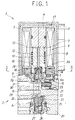
- FIG. 1 illustrates one embodiment of a solenoid valve which comprises a main valve part 2 to switch a fluid flow passage by a valve member, and a solenoid 1 to open/close the valve member through the energization to a coil 9.
- the main valve part 2 is provided with a valve body 20, and the valve body 20 is provided with an input port P to be connected to a feed source of compressed air, an output port A to be connected to an actuator such as an air cylinder, and a discharge port R to discharge the air outside.
- a feed valve seat 21 is arranged in a flow passage to connect the input port P to the output port A through a communication hole 29 inside the valve body 20, and a discharge valve seat 22 is arranged in a flow passage to connect the output port A to the discharge port R so that they are opposite to each other on the same axis.
- a feed valve member 24 to open/close the feed valve seat 21 is arranged in a feed valve chest 23 in which the feed valve seat 21 is opened in a condition where the feed valve member is held by a moving core 3 of the solenoid 1.
- a discharge valve member 26 to open/close the discharge valve seat 22 is arranged in a discharge valve chest 25 in which the discharge valve seat 22 is opened in a condition where the discharge valve member is urged in a direction to close the discharge valve seat 22 by a valve spring 28 which is provided in a compressed condition between a spring seat 27 and the discharge valve member.
- a push rod 30 is inserted in the communication hole 29 so as not to prevent the flow of the compressed air.
- a lower end of the push rod 30 is abutted on an upper surface of a cap-like pressing member 31 mounted on the discharge valve member 26, while an upper end of the push rod 30 is abutted on a lower surface of a cap 15 mounted on a lower end of the variable core 3 in the solenoid 1.
- the push rod 30 is pushed down by the moving core 3 when the moving core 3 is lowered and the feed valve member 24 closes the feed valve seat 21, and pushes down the discharge valve member 26 to release the discharge valve seat 22.
- the push rod is pushed down by the urging of the valve spring 28 by releasing the pressure of the discharge valve member 26, and the discharge valve seat 22 is closed by the discharge valve member 26.
- the solenoid 1 is provided with the coil 9 formed by winding a conductive wire around a bobbin 17, a magnetic frame 5 to surround the coil 9, a core hole 10 formed at the center of the bobbin 17, a fixed core 4 which is fixed to one end side of the core hole 10 in an airtight manner and magnetically coupled with the magnetic frame through the contact with the magnetic frame 5, the moving core 3 which is slidably inserted in the other side of the core hole 10, and a return spring 12 to urge the moving core 3 in a direction away from the fixed core 4.
- the core hole 10 comprises a center hole in the bobbin 17, and a center hole 6a in a magnetic plate 6 which forms a part of the magnetic frame 5 connected thereto, and the moving core 3 is provided so that its tip is projected in the feed valve chest 23 through the center hole 6a in the magnetic plate 6.
- the moving core 3 is provided with a recess 3a in a lower end face, and the feed valve member 24 and a valve spring 16 to urge the feed valve member 24 in a projecting direction from the recess 3a are accommodated in the recess 3a.
- the cap 15 formed of an elastic material such as a synthetic resin is mounted on a small diameter part 3b of a lower end part of the moving core 3.
- a communication hole 8 to flow the compressed air in/out of a space 13 between the moving core 3 and the fixed core 4 is provided in a center part of the moving core 3.
- the communication hole 8 is provided so that the moving core 3 is not affected by the air pressure by balancing the air pressure to be applied on each end of the moving core by flowing the compressed air in/out of the space 13 while the moving core 3 is in operation.
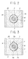
- a gap part 11 of the uniform size surrounding the periphery of the moving core 3 is formed between the magnetic plate 60 and the moving core 3 in the center hole 6a of the magnetic plate 60, and a magnetic fluid 7 is accommodated in the gap part 11.
- the magnetic fluid 7 is obtained by mixing iron powders in, for example, an oil or other fluid, and its viscosity is rapidly increased by the influence of the magnetic field.
- the magnetic fluid 7 is subjected to the influence of the magnetic force through the magnetic plate 6 when the magnetic frame 5 and the fixed core 4 are excited by the energization to the coil 9 and the moving core 3 is attracted to the fixed core 4, and the viscosity is increased to drop the attraction speed of the moving core 3.
- an appropriate magnetic unit is preferably provided.
- a permanent magnet 14 mounted on each side end of the magnetic plate 6 across the moving core 3 is shown in the embodiment illustrated as an example of the magnetic unit.
- the magnetic fluid 7 is surely maintained in the gap part 11 by the action of the magnetic force from the permanent magnet 14 and the surface tension of the fluid itself by mounting the permanent magnet 14 on the magnetic plate 6.
- a seal mechanism to prevent the leakage of the magnetic fluid 7 need not be specially provided, but the seal mechanism may be added according to the condition of a place to form the gap part 11 or the viscosity of the magnetic fluid 7, and further, the seal mechanism together with the magnetic unit may be provided.
- the magnetic force of the permanent magnet 14 is naturally of the magnitude so that the operation of the solenoid 1 is not adversely affected.
- the viscosity of the magnetic fluid 7 is rapidly increased by the influence of the magnetic force when the coil 9 is energized, and the attraction speed of the moving core 3 to the fixed core 4 is reduced.
- the moving core 3 is prevented from being strongly collided with the fixed core 4, the collision noise is reduced, and at the same time, the wear of an attraction surface of each core is prevented.
- the solenoid valve of this construction is suitable for a mechanical appliance to be used in a silent environment such as medial facilities.
- the magnetic fluid 7 is interposed in the gap between the moving core 3 and the magnetic plate 6, no magnetic gap is present between the moving core 3 and the magnetic plate 6 to reduce the magnetic resistance, and the efficiency of the solenoid is increased to save the power. Still further, the magnetic fluid 7 is substantially and uniformly maintained around the whole periphery of the moving core 3, the moving core 3 is prevented from being brought into slidable contact with the magnetic plate 6 due to the mutual attraction, and the mutual friction is prevented, and the operation of the moving core becomes stable.
- the communication hole 8 to flow the compressed air in/out of the space between the moving core 3 and the fixed core 4 is provided in the center of the moving core 3, and is not directly intersected with the gap part 11, no force is applied to the magnetic fluid 7 by the flow of- the compressed air, and the magnetic fluid 7 is stably maintained between the moving core 3 and the magnetic plate 6.
- the permanent magnet 14 is used as the magnetic unit to maintain the magnetic fluid 7 in the gap part 11, but in place of the permanent magnet 14, at least one of the magnetic plate 6 and the moving core 3 is formed of a hard or semi-hard ferromagnetic material, and its remanent magnetism can be used as the magnetic unit. Alternatively, such a remanent magnetism may be used together with the permanent magnet.
- the position at which the gap part 11 is provided is not limited in the center hole 6a in the magnetic plate 6, but may be other position of the core hole 10.
- the magnetic fluid 7 is only accommodated in the gap part 11 formed around the moving core 3 so that the moving core 3 is subjected to the influence of the magnetic force when it is attracted by the fixed core 4 due to the energization to the coil 9.
- FIG. 3 shows the second embodiment of the present invention, and the second embodiment is different from the first embodiment in that the communication hole 8 to balance the force by the air pressure at each end of the moving core 3 is formed in the center part of the moving core 3 in the first embodiment, while a plurality of communication holes 8a are formed in an inner wall of the core hole 10 or in an outer surface of the moving core 3 in the second embodiment.
- the communication holes 8a can be intersected with the gap part 11 in which the magnetic fluid 7 is accommodated, and when it is intersected, the magnetic unit effectively functions because the magnetic fluid 7 is prevented from flowing out of the gap part 11 through the communication holes 8a.
- a three-port valve is used in each of the above-described embodiments, but the solenoid valve of the present invention is not limited thereto, but any valves having a plurality of ports including a two-port valve, a four-port valve or a five-port valve may be used.
- the magnetic fluid is accommodated in the gap part formed around the moving core, and the viscosity of the magnetic fluid is increased by the influence of the magnetic force when the solenoid is energized, the speed at which the moving core is attracted to the fixed core is reduced, both cores are prevented from being strongly collided with each other, the collision noise is reduced, and the wear of each attraction surface is prevented.
- the magnetic fluid is interposed between the moving core and the magnetic plate, no magnetic gap is present between the moving core and the magnetic plate, the magnetic resistance is reduced, and the efficiency of the solenoid is increased to save the power.
- the magnetic fluid is substantially and uniformly maintained around the whole periphery of the moving core, the moving core is prevented from being brought into slidable contact with the magnetic plate due to the mutual attraction, the mutual friction is prevented, and the operation of the moving core becomes stable.
Landscapes
- Engineering & Computer Science (AREA)
- General Engineering & Computer Science (AREA)
- Mechanical Engineering (AREA)
- Magnetically Actuated Valves (AREA)
Applications Claiming Priority (4)
| Application Number | Priority Date | Filing Date | Title |
|---|---|---|---|
| JP31066798 | 1998-10-30 | ||
| JP10310667A JP2000130632A (ja) | 1998-10-30 | 1998-10-30 | 電磁弁 |
| JP31066698 | 1998-10-30 | ||
| JP10310666A JP2000130628A (ja) | 1998-10-30 | 1998-10-30 | 電磁弁 |
Publications (2)
| Publication Number | Publication Date |
|---|---|
| EP0997675A2 true EP0997675A2 (de) | 2000-05-03 |
| EP0997675A3 EP0997675A3 (de) | 2001-07-18 |
Family
ID=26566414
Family Applications (1)
| Application Number | Title | Priority Date | Filing Date |
|---|---|---|---|
| EP99308480A Withdrawn EP0997675A3 (de) | 1998-10-30 | 1999-10-26 | Elektromagnetisches Ventil |
Country Status (5)
| Country | Link |
|---|---|
| US (1) | US6213445B1 (de) |
| EP (1) | EP0997675A3 (de) |
| KR (1) | KR20000029421A (de) |
| CN (1) | CN1253251A (de) |
| TW (1) | TW424857U (de) |
Cited By (1)
| Publication number | Priority date | Publication date | Assignee | Title |
|---|---|---|---|---|
| CN109027343A (zh) * | 2017-06-08 | 2018-12-18 | 盾安环境技术有限公司 | 一种三通电磁阀 |
Families Citing this family (30)
| Publication number | Priority date | Publication date | Assignee | Title |
|---|---|---|---|---|
| DE19954024C2 (de) * | 1999-11-10 | 2003-01-02 | Thomas Magnete Gmbh | Elektromagnetische Antriebsvorrichtung für Ventilschieber von Magnetventilen |
| JP4247314B2 (ja) * | 2000-12-25 | 2009-04-02 | Smc株式会社 | 電磁弁用ソレノイド |
| JP3842990B2 (ja) * | 2001-08-13 | 2006-11-08 | Smc株式会社 | 電磁弁用ソレノイドの可動鉄心及びその製造方法 |
| JP3857094B2 (ja) * | 2001-09-04 | 2006-12-13 | Smc株式会社 | 電磁弁 |
| JP2003227578A (ja) * | 2002-02-04 | 2003-08-15 | Rinnai Corp | 電磁式給水弁 |
| KR100484392B1 (ko) * | 2002-11-15 | 2005-04-22 | 주식회사 디에이텍 | 전자식 밸브 |
| JP2005069072A (ja) * | 2003-08-22 | 2005-03-17 | Eagle Ind Co Ltd | 容量制御弁 |
| KR20050069454A (ko) * | 2003-12-31 | 2005-07-05 | 주식회사 아셀텍 | 3포트 솔레노이드밸브 |
| US7163188B1 (en) * | 2004-07-30 | 2007-01-16 | Emerson Electric Co. | Solenoid valve for fluid flow |
| US7163248B2 (en) * | 2004-11-08 | 2007-01-16 | Lear Corporation | Automotive console with adjustable armrest |
| US20060100764A1 (en) * | 2004-11-08 | 2006-05-11 | Adams Robert J | Adjustable automotive center console |
| US7240941B2 (en) * | 2004-11-08 | 2007-07-10 | Lear Corporation | Vehicle storage assembly with adjustable door |
| KR20060084624A (ko) * | 2005-01-20 | 2006-07-25 | 주식회사 아셀텍 | 밸브 |
| US20070056644A1 (en) * | 2005-09-13 | 2007-03-15 | Boddy Douglas E | Damper spool |
| US20070228311A1 (en) * | 2006-03-28 | 2007-10-04 | Beneker Gerrit V | Pressure balanced valve |
| CN100426435C (zh) * | 2006-06-26 | 2008-10-15 | 张宇群 | 一种电磁式电源总开关 |
| HU226838B1 (en) * | 2008-01-29 | 2009-12-28 | Daniel Wamala | Electromagnetically operated mechanical actuator |
| CN101498379B (zh) * | 2008-02-03 | 2011-09-07 | 浙江三花股份有限公司 | 电磁阀 |
| CN102348919B (zh) * | 2009-03-16 | 2014-04-02 | 阿尔特弥斯智能动力有限公司 | 电子控制的阀门 |
| JP5560425B2 (ja) * | 2010-02-17 | 2014-07-30 | Smc株式会社 | 電磁弁用ソレノイド |
| JP5644757B2 (ja) * | 2011-12-28 | 2014-12-24 | 株式会社日本自動車部品総合研究所 | 圧力制御装置 |
| WO2015038600A1 (en) * | 2013-09-12 | 2015-03-19 | Labinal, Llc | Solenoid including a dual coil arrangement to control leakage flux |
| CN104712825B (zh) * | 2015-02-06 | 2018-06-05 | 瑞立集团瑞安汽车零部件有限公司 | 一种可与多种母插头组件插接的电磁阀 |
| DE102015219207B3 (de) * | 2015-10-05 | 2017-02-09 | Conti Temic Microelectronic Gmbh | Druckverteiler für ein Kraftfahrzeug |
| SE540880C2 (en) * | 2016-09-28 | 2018-12-11 | Freevalve Ab | Multi-way valve as well as actuator comprising such a multi-way valve |
| WO2018130987A1 (en) * | 2017-01-13 | 2018-07-19 | L&T Technology Services Limited | Valve assembly including brake control mechanism |
| KR101947904B1 (ko) * | 2017-06-05 | 2019-02-13 | 주식회사 현대케피코 | 솔레노이드밸브 벤트 구조 |
| US10221959B1 (en) | 2017-10-03 | 2019-03-05 | Edward P. Davis | Higher speed lower torque magnetic valve actuator |
| CN111011199B (zh) * | 2019-12-26 | 2021-07-20 | 淄博职业学院 | 一种自动化无土栽培生产线 |
| CN111452079B (zh) * | 2020-05-18 | 2024-11-29 | 成都卡诺普机器人技术股份有限公司 | 一种机器人用电磁铁夹具 |
Family Cites Families (10)
| Publication number | Priority date | Publication date | Assignee | Title |
|---|---|---|---|---|
| JPS5771108A (en) * | 1980-10-21 | 1982-05-01 | Aisin Seiki Co Ltd | Electromagnetic driving device |
| DE3043274A1 (de) * | 1980-11-15 | 1982-07-01 | Wabco Fahrzeugbremsen Gmbh, 3000 Hannover | Magnetventil |
| JPS57145565A (en) * | 1981-03-02 | 1982-09-08 | Mitsubishi Electric Corp | Electromagnetic driving unit |
| JPS63180783U (de) * | 1987-05-14 | 1988-11-22 | ||
| US5353839A (en) * | 1992-11-06 | 1994-10-11 | Byelocorp Scientific, Inc. | Magnetorheological valve and devices incorporating magnetorheological elements |
| US5441233A (en) * | 1994-03-18 | 1995-08-15 | Smc Corporation | Electromagnetic valve |
| US5517096A (en) * | 1995-02-07 | 1996-05-14 | Trw Inc. | Power steering system |
| WO1998004846A1 (en) * | 1996-07-30 | 1998-02-05 | The Board Of Regents Of The University And Community College System Of Nevada | Magneto-rheological fluid damper |
| US5969589A (en) * | 1996-08-28 | 1999-10-19 | Ferrofluidics Corporation | Quiet ferrofluid solenoid |
| US6095486A (en) * | 1997-03-05 | 2000-08-01 | Lord Corporation | Two-way magnetorheological fluid valve assembly and devices utilizing same |
-
1999
- 1999-10-05 TW TW088216865U patent/TW424857U/zh not_active IP Right Cessation
- 1999-10-07 US US09/413,886 patent/US6213445B1/en not_active Expired - Fee Related
- 1999-10-26 EP EP99308480A patent/EP0997675A3/de not_active Withdrawn
- 1999-10-29 CN CN99123261A patent/CN1253251A/zh active Pending
- 1999-10-29 KR KR1019990047501A patent/KR20000029421A/ko not_active Ceased
Non-Patent Citations (1)
| Title |
|---|
| None |
Cited By (2)
| Publication number | Priority date | Publication date | Assignee | Title |
|---|---|---|---|---|
| CN109027343A (zh) * | 2017-06-08 | 2018-12-18 | 盾安环境技术有限公司 | 一种三通电磁阀 |
| CN109027343B (zh) * | 2017-06-08 | 2022-03-08 | 盾安环境技术有限公司 | 一种三通电磁阀 |
Also Published As
| Publication number | Publication date |
|---|---|
| EP0997675A3 (de) | 2001-07-18 |
| KR20000029421A (ko) | 2000-05-25 |
| TW424857U (en) | 2001-03-01 |
| US6213445B1 (en) | 2001-04-10 |
| CN1253251A (zh) | 2000-05-17 |
Similar Documents
| Publication | Publication Date | Title |
|---|---|---|
| US6213445B1 (en) | Solenoid valve with magnetic fluid damper | |
| US7959129B2 (en) | Two-port solenoid valve | |
| US3707992A (en) | Electromagnetic valve assembly | |
| JP3590765B2 (ja) | 電磁弁 | |
| US5318071A (en) | High-speed three-way solenoid valve for pressurized fluid, such as compressed air circuits | |
| US5467797A (en) | Two-position three-way solenoid valve | |
| EP0687843A1 (de) | Druckausgeglichenes Elektromagnetventil | |
| TWI748176B (zh) | 電磁閥 | |
| EP1219877A1 (de) | Selbsthaltendes Elektromagnetventil | |
| US2619121A (en) | Solenoid operated valve | |
| EP3919795A1 (de) | Elektromagnetisches gasventil | |
| JPH04502192A (ja) | ガス交換弁のための操作装置 | |
| JPS60159481A (ja) | 制御弁 | |
| JP2659317B2 (ja) | 高速作動電磁弁 | |
| CN113324044A (zh) | 一种新型电磁阀 | |
| CN215110538U (zh) | 一种新型电磁阀 | |
| JP3140699B2 (ja) | ゲート式電磁弁 | |
| JP2000130632A (ja) | 電磁弁 | |
| JP2000130628A (ja) | 電磁弁 | |
| CN219452893U (zh) | 先导式电磁阀和机动车辆 | |
| JP2003083465A (ja) | 電磁弁 | |
| RU2190143C2 (ru) | Электромагнитный клапан | |
| JPH0353095Y2 (de) | ||
| JPH0720461Y2 (ja) | 電磁弁 | |
| JPS62171575A (ja) | ソレノイドアクチユエ−タバルブ |
Legal Events
| Date | Code | Title | Description |
|---|---|---|---|
| PUAI | Public reference made under article 153(3) epc to a published international application that has entered the european phase |
Free format text: ORIGINAL CODE: 0009012 |
|
| 17P | Request for examination filed |
Effective date: 19991108 |
|
| AK | Designated contracting states |
Kind code of ref document: A2 Designated state(s): DE FR GB IT |
|
| AX | Request for extension of the european patent |
Free format text: AL;LT;LV;MK;RO;SI |
|
| PUAL | Search report despatched |
Free format text: ORIGINAL CODE: 0009013 |
|
| AK | Designated contracting states |
Kind code of ref document: A3 Designated state(s): AT BE CH CY DE DK ES FI FR GB GR IE IT LI LU MC NL PT SE |
|
| AX | Request for extension of the european patent |
Free format text: AL;LT;LV;MK;RO;SI |
|
| RIC1 | Information provided on ipc code assigned before grant |
Free format text: 7F 16K 31/06 A, 7F 15B 21/06 B |
|
| AKX | Designation fees paid |
Free format text: DE FR GB IT |
|
| STAA | Information on the status of an ep patent application or granted ep patent |
Free format text: STATUS: THE APPLICATION IS DEEMED TO BE WITHDRAWN |
|
| 18D | Application deemed to be withdrawn |
Effective date: 20020119 |